1
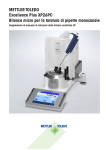
I-E
VALVOLE DI SFIORO
RELIEF VALVES
MANUALE TECNICO MT091
TECHNICAL MANUAL MT091
ISTRUZIONI PER L’INSTALLAZIONE, LA MESSA IN SERVIZIO E LA MANUTENZIONE
INSTALLATION, COMMISSIONING AND MAINTENANCE INSTRUCTIONS
MANUALE TECNICO MT091
TECHNICAL MANUAL MT091
VS/AM 56
VS/AM 58
VS/AM 55
Edizione Febbraio 2001
Issue February 2001
2
MANUALE TECNICO MT091
TECHNICAL MANUAL MT091
AVVERTENZE
PRECAUTIONS
AVVERTENZE GENERALI
GENERAL PRECAUTIONS
- L’apparecchiatura descritta in questo manuale è un
dispositivo soggetto a pressione inserito in sistemi
pressurizzati;
- l’apparecchiatura in questione è normalmente inserita in sistemi che trasportano gas infiammabili (ad
esempio gas naturale).
- The apparatus described in this manual is a device
subject to pressure installed in systems under pressure;
- the apparatus in question is normally installed in
systems for transporting flammable gases (natural
gas, for example).
AVVERTENZE PER GLI OPERATORI
PRECAUTIONS FOR THE OPERATORS
Prima di procedere all’installazione, messa in servizio o
manutenzione gli operatori devono:
- prendere visione delle disposizioni di sicurezza
applicabili all’installazione in cui devono operare;
- ottenere le necessarie autorizzazioni ad operare
quando richieste;
- dotarsi delle necessarie protezioni individuali
(casco, occhiali, ecc.);
- assicurarsi che l’area in cui si deve operare sia dotata delle protezioni collettive previste e delle necessarie indicazioni di sicurezza.
Before proceeding with installation, commissioning or
maintenance, operators must:
- examine the safety provisions applicable to the
installation in which they must work;
- obtain the authorisations necessary for working
when so required;
- use the necessary means of individual protection
(helmet, goggles, etc.);
- ensure that the area in which they operate is fitted
with the means of collective protection envisaged
and with the necessary safety indications.
MOVIMENTAZIONE
La movimentazione dell’apparecchiatura e dei suoi
componenti deve essere eseguita dopo aver valutato
che i mezzi di sollevamento siano adeguati ai carichi da
sollevare (capacità di sollevamento e funzionalità). La
movimentazione dell’apparecchiatura deve essere eseguita utilizzando i punti di sollevamento previsti sull’apparecchiatura stessa.
L’impiego di mezzi motorizzati è riservato al personale
a ciò preposto.
HANDLING
INSTALLAZIONE
INSTALLATION
Qualora l’installazione dell’apparecchiatura richieda
l’applicazione in campo di raccordi a compressione,
questi devono essere installati seguendo le istruzioni
del produttore dei raccordi stessi. La scelta del raccordo deve essere compatibile con l’impiego specificato
per l’apparecchiatura e con le specifiche di impianto
quando previste.
If the installation of the apparatus requires the application
of compression fittings in the field, these must be installed following the instructions of the manufacturer of
the fittings themselves. The choice of the fitting must be
compatible with the use specified for the apparatus and
with the specifications of the system when envisaged.
MESSA IN SERVIZIO
COMMISSIONING
La messa in servizio deve essere eseguita da personale
adeguatamente preparato.
Durante le attività di messa in servizio il personale non
strettamente necessario deve essere allontanato e deve
essere adeguatamente segnalata l’area di interdizione
(cartelli, transenne, ecc.).
Verificare che le tarature dell’apparecchiatura siano
quelle richieste; eventualmente provvedere al loro ripristino ai valori richiesti secondo le modalità indicate
oltre nel manuale.
Durante la messa in servizio devono essere valutati i
rischi determinati da eventuali scarichi in atmosfera di
gas infiammabili o nocivi.
Per installazione su reti di distribuzione per gas naturale occorre considerare il rischio di formazioni di miscela esplosiva (gas/aria) all’interno delle tubazioni.
Commissioning must be carried out by adequately trained
personnel.
During the commissioning activities, the personnel not
strictly necessary must be ordered away and the no-go
area must be properly signalled (signs, barriers, etc.).
Check that the settings of the apparatus are those
requested; if necessary, reset them to the required
values in accordance with the procedures indicated in
the manual.
When commissioning, the risks associated with any
discharges into the atmosphere of flammable or
noxious gases must be assessed.
In installations in natural gas distribution networks, the
risk of the formation of explosive mixtures (gas/air)
inside the piping must be considered.
The handling of the apparatus and of its components
must only be carried out after ensuring that the lifting
gear is adequate for the loads to lift (lifting capacity
and functionality). The apparatus must be handled
using the lifting points provided on the apparatus itself.
Motorised means must only be used by the persons in
charge of them.
3
MANUALE TECNICO MT091
TECHNICAL MANUAL MT091
INDICE
INDEX
1.0
INTRODUZIONE
PAGINA 5
1.0
INTRODUCTION
1.1
PRINCIPALI CARATTERISTICHE
5
1.1
MAIN FEATURES
5
1.2
VS/AM 55
6
1.2
VS/AM 55
6
1.3
VS/AM 56
7
1.3
VS/AM 56
7
1.4
VS/AM 58
8
1.4
VS/AM 58
8
1.5
MOLLE DI TARATURA
9
1.5
SETTING SPRINGS
9
2.0
INSTALLAZIONE
11
2.0
INSTALLATION
11
2.1
INSTALLAZIONE DIRETTA SULLA LINEA
11
2.2
INSTALLAZIONE CON VALVOLA DI
11
2.1
DIRECT INSTALLATION IN THE LINE
11
2.2
INSTALLATION WITH ON/OFF VALVE
11
3.0
START UP
12
INTERCETTAZIONE
PAGE 5
3.0
MESSA IN SERVIZIO
12
3.1
GENERALITA’
12
3.1
GENERAL
12
3.2
MESSA IN GAS, CONTROLLO TENUTA
13
3.2
GAS INPUT, CONTROL OF EXTERNAL
13
TIGHTNESS AND SETTING
ESTERNA E TARATURE
14
3.3
3.3.1 INSTALLAZIONE DIRETTA SULLA LINEA
15
3.3.1 DIRECT INSTALLATION IN THE LINE
14
3.3.2 INSTALLAZIONE CON VALVOLA DI
14
3.3.2 INSTALLATION WITH ON/OFF VALVE
14
4.0
TROUBLE-SHOOTING
15
5.0
MAINTENANCE
16
5.1
GENERAL
16
5.2
PROCEDURE FOR DIASASSEMBLY AND
17
3.3
CONTROLLO TARATURA
CHECKING THE SETTING
14
INTERCETTAZIONE
4.0
ANOMALIE E INTERVENTI
15
5.0
MANUTENZIONE
16
5.1
GENERALITA’
16
5.2
PROCEDURA PER LO SMONTAGGIO E
17
REASSEMBLY OF THE VS/AM 55 RELIEF VALVE
RIMONTAGGIO DELLA VALVOLA VS/AM 55
5.3
PROCEDURA PER LO SMONTAGGIO E
5.3
20
PROCEDURA PER LO SMONTAGGIO E
5.4
23
LISTA DEI RICAMBI CONSIGLIATI
PROCEDURE FOR DIASASSEMBLY AND
23
REASSEMBLY OF THE VS/AM 58 RELIEF VALVE
RIMONTAGGIO DELLA VALVOLA VS/AM 58
6.0
20
REASSEMBLY OF THE VS/AM 56 RELIEF VALVE
RIMONTAGGIO DELLA VALVOLA VS/AM 56
5.4
PROCEDURE FOR DIASASSEMBLY AND
27
6.0
4
LIST OF RECOMMENDED SPARES
27
MANUALE TECNICO MT091
1.0
TECHNICAL MANUAL MT091
INTRODUZIONE
1.0
INTRODUCTION
Questo manuale si propone di fornire le informazioni
essenziali per l’installazione, la messa in servizio, lo
smontaggio, il rimontaggio e la manutenzione delle valvole di sfiato VS/AM.
Si ritiene comunque opportuno fornire in questa sede
una breve illustrazione delle principali caratteristiche
del regolatore e dei suoi accessori.
This manual proposes to provide the essential information for the installation, start-up, disassembly, reassembly and maintenance of the relief valves VS/AM.
It is also appropriate, however, to provide a brief illustration of the main features of the regulator and of its
components.
1.1
1.1
PRINCIPALI CARATTERISTICHE
Le valvole di sfioro della serie VS/AM sono dispositivi di
sicurezza (SBV) che provvedono a scaricare all’esterno
una certa quantità di gas quando la pressione nel punto
di controllo supera quella di taratura (pressione di rottura bolla) a causa di eventi non duraturi quali per
esempio la chiusura du valvole di intercettazione in un
tempo molto ridotto e/o surriscaldamento del gas con
portata richiesta nulla.
Lo scarico del gas all’esterno può, per esempio, evitare
l’intervento dei dispositivi di blocco per cause transitorie non derivanti da danni ai riduttori. Ovviamente la
quantità di gas scaricata dipende dalla entità della
sovrapressione rispetto alla temperatura.
Le caratteristiche principali di queste sono:
- pressione di progetto del corpo:
tipo 55: 16 bar
tipo 56: 18,9 bar
tipo 58: 100 bar
- temperatura di progetto:
-10÷50° C;
(a richiesta temperature inferiori o superiori);
- intervallo di regolazione consigliato (Who):
tipo 55/B: 20÷250 mbar
tipo 55/M: 200÷700 mbar
tipo 56: 420÷7000 mbar
tipo 58: 2÷44 bar
- precisione di intervento alla rottura bolla (AG):
tipo 55: ±2,5%
tipo 56: ±1,5%
tipo 58: ±1% 28 bar ≤ taratura ≤ 44 bar
±2% 8,5 bar ≤ taratura ≤ 28 bar
±3% 2 bar ≤ taratura ≤ 8,5 bar
MAIN FEATURES
The relief valves in the VS/AM Series are safety devices
(SBV) for discharging a certain amount of gas when the
pressure at the control point exceedes a given level
(bubble-bursting pressure) due to any temporary occurance such as the momentary shutting of the on/off
valve and/or the overheating of the gas with no flow
requirement.
Discharge of the gas can, for example, avoid any intervention by blocking devices in the case of transient causes not regarding damage to the regulators. Clearly, the
amount of discharged gas depends on the entity of the
excess pressure in relation of the pressure setting.
The main features of the valves are:
- body design pressure:
type 55: 16 bar
type 56: 18,9 bar
type 58: 100 bar
- design temperature:
-10÷50° C;
(lower or higher temperatures on request)
- suggested adjustment rauge (Who)
type 55/B: 20÷250 mbar
type 55/M: 200÷700 mbar
type 56: 420÷7000 mbar
type 58: 2÷44 bar
- bubble-tightness accuracy (AG):
type 55: ±2,5%
type 56: ±1,5%
type 58: ±1% 28 bar ≤ setting ≤ 44 bar
±2% 8,5 bar ≤ setting ≤ 28 bar
±3% 2 bar ≤ setting ≤ 8,5 bar
5
MANUALE TECNICO MT091
1.2
TECHNICAL MANUAL MT091
VS/AM 55 (FIG. 1)
1.2
Esso si fonda sul confronto tra la spinta sulla membrana 24 derivante dalla pressione del gas da controllare e
la spinta derivante dalla molla di taratura 20.
In questo confronto intervengono il peso dell’equipaggio mobile, le spinte statiche e quelle dinamiche residue
sull’otturatore 4.
Quando la spinta derivante dalla pressione del gas
supera quella della molla di taratura, l’otturatore 4 viene
sollevato con conseguente scarico di una certa quantità
di gas.
Non appena la pressione scende al di sotto del valore di
taratura, l’otturatore ritorna in posizione di chiusura. Il
controllo e la registrazione dell’intervento della valvola
di sfioro può essere eseguito ruotando opportunamente la ghiera di regolazione interna 14.
VS/AM 55 (FIG. 1)
It is based on the contrast between the thrust on the
diaphragm 24 deriving from the pressure of the gas to
control and the thrust from the setting spring 20. The
weight of the mobile assembly, the static thrust and the
residual dynamic thrust on the obturator 4 also contribute to this contrast.
When the thrust deriving from the pressure of the gas
exceeds that of the setting spring, the obturator 4 is
raised and a certain quantity of gas is released as a
result.
As soon as the pressure drops below the set-point, the
obturator returns to the closed position. Proceed by
turning the internal adjustment ring 14 appropriately to
control and adjust intervention of the relief valve.
Fig. 1
6
MANUALE TECNICO MT091
1.3
TECHNICAL MANUAL MT091
VS/AM 56 (FIG. 2)
1.3
Esso si fonda sul confronto tra la spinta sulla membrana 24 derivante dalla pressione del gas da controllare e
la spinta derivante dalla molla di taratura 20.
In questo confronto intervengono il peso dell’equipaggio mobile, le spinte statiche e quelle dinamiche residue
sull’otturatore 4.
Quando la spinta derivante dalla pressione del gas
supera quella della molla di taratura, l’otturatore 4 viene
sollevato con conseguente scarico di una certa quantità
di gas.
Non appena la pressione scende al di sotto del valore di
taratura, l’otturatore ritorna in posizione di chiusura. Il
controllo e la registrazione dell’intervento della valvola
di sfioro può essere eseguito ruotando opportunamente la ghiera di regolazione interna 13.
VS/AM 56 (FIG. 2)
It is based on the contrast between the thrust on the
diaphragm 24 deriving from the pressure of the gas to
control and the thrust from the setting spring 20. The
weight of the mobile assembly, the static thrust and the
residual dynamic thrust on the obturator 4 also contribute to this contrast.
When the thrust deriving from the pressure of the gas
exceeds that of the setting spring, the obturator 4 is
raised and a certain quantity of gas is released as a
result.
As soon as the pressure drops below the set-point, the
obturator returns to the closed position. Proceed by
turning the internal adjustment ring 13 appropriately to
control and adjust intervention of the relief valve.
Fig. 2
7
MANUALE TECNICO MT091
1.4
TECHNICAL MANUAL MT091
VS/AM 58 (FIG. 3)
1.4
Esso si fonda sul confronto tra la spinta sul pistone 4
derivante dalla pressione del gas da controllare e la
spinta derivante dalla molla di taratura 20.
In questo confronto intervengono il peso dell’equipaggio mobile, le spinte statiche e quelle dinamiche residue
sull’otturatore 4.
Quando la spinta derivante dalla pressione del gas
supera quella della molla di taratura, l’otturatore 4 viene
sollevato con conseguente scarico di una certa quantità
di gas.
Non appena la pressione scende al di sotto del valore di
taratura, l’otturatore ritorna in posizione di chiusura. Il
controllo e la registrazione dell’intervento della valvola
di sfioro può essere eseguito ruotando opportunamente la ghiera di regolazione 9.
VS/AM 58 (FIG. 3)
It is based on the contrast between the thrust on the
diaphragm 24 deriving from the pressure of the gas to
control and the thrust from the setting spring 20. The
weight of the mobile assembly, the static thrust and the
residual dynamic thrust on the obturator 4 also contribute to this contrast.
When the thrust deriving from the pressure of the gas
exceeds that of the setting spring, the obturator 4 is
raised and a certain quantity of gas is released as a
result.
As soon as the pressure drops below the set-point, the
obturator returns to the closed position. Proceed by
turning the internal adjustment plug 9 appropriately to
control and adjust intervention of the relief valve.
Fig. 3
8
MANUALE TECNICO MT091
1.5
TECHNICAL MANUAL MT091
Tab. 1 Molle di taratura
1.5
1.5.1 VS/AM 55
(dopo ottobre 2000)
Table 1 Setting springs
1.5.1 VS/AM 55
(after october 2000)
Tab. 1 VS/AM 55
Tab. 1 VS/AM 55
Codice
Code
d
1
2700496
1.8
115
12
2
2700561
2
115
11.5
20 ÷ 30
3
2700631
2.2
115
11.5
30 ÷ 40
4
2700907
2.7
5
2700974
2.8
6
2701141
3.2
7
2701886
4.6
8
2701886
9
De
Lo
Campo di taratura in mbar • Setting range in mbar
BP
MP
TR
it
15 ÷ 20
115
12
40 ÷ 70
115
11
70 ÷100
115
11.5
100 ÷ 180
97
12.5
180 ÷ 450
4.6
97
12.5
300 ÷ 700
2702060
5
100
10.5
700 ÷ 1100
10
2702275
5.5
100
10
1100 ÷ 2000
11
2702644
6.5
100
10.25
2000 ÷ 3000
34
1.5.2 VS/AM 55
(fino ad ottobre 2000)
1.5.2 VS/AM 55
(only october 2000)
Tab. 2 VS/AM 55 - Tab. 2 VS/AM 55
Codice/Code
Colore/Colour
d
2700560
BIANCO-ROSSO/WHITE-RED
2
De
Lo
i
it
Campo di taratura in mbar
Setting range in mbar
90
10
12
17 ÷ 25
2700496
BIANCO/WHITE
1.8
115
9.5
11.5
23 ÷ 27
2700661
GIALLO/YELLOW
5
115
9.5
11.5
25 ÷ 33
2700720
ARANCIO/ORANGE
2.3
115
11.75
13.75
33 ÷ 63
2700816
ROSSO/RED
2.5
115
11
13
45 ÷ 75
2700974
VERDE/GREEN
2.8
115
9
11
72 ÷ 115
2701030
NERO/BLACK
3
115
10
12
90 ÷ 140
2701141
BLU/BLUE
3.2
115
9.25
11.25
110 ÷ 170
34
2701250
MARRONE/BROWN
3.5
115
10
12
150 ÷ 250
2701524
VIOLA/VIOLET
4
100
8.5
10.5
210 ÷ 450
2701780
AZZURRO/AZURE
4.5
100
9
11
350 ÷ 700
1.5.3 VS/AM 55 DVGW
1.5.3 VS/AM 55 DVGW
Tab. 3 VS/AM 55 DVGW - Tab. 3 VS/AM 55 DVGW
Codice/Code
Lo
i
it
Campo di taratura in mbar
Setting range in mbar
2.0
115
9.5
11.5
28 ÷ 34
2.3
115
11
13
34 ÷ 48
2.5
115
10.5
12.75
47 ÷ 72
Colore/Colour
d
2700561
GIALLO/YELLOW
2700720
ARANCIO/ORANGE
2700816
ROSSO/RED
2700974
VERDE/GREEN
2.8
2701141
BLU/BLUE
3.2
2701524
VIOLA/VIOLET
2701780
2701524
2702060
De
115
9
11
70 ÷ 110
115
9.5
11.5
105 ÷ 180
4
100
8.5
10.5
170 ÷ 320
AZZURRO/AZURE
4.5
100
9
11
310 ÷ 540
VIOLA/VIOLET
4
100
8.5
10.5
210 ÷ 450
GRIGIO/GREY
5
100
8.25
10.5
460 ÷ 700
34
9
BP
MP
MANUALE TECNICO MT091
TECHNICAL MANUAL MT091
1.5.4 VS/AM 56
1.5.4 VS/AM 56
Tab. 4 VS/AM 56 - Tab. 4 VS/AM 56
Codice/Code
Lo
i
it
Campo di taratura in mbar
Setting range in mbar
3.5
115
10.5
12.75
420 ÷ 590
4
100
7.5
9.75
560 ÷ 1080
4.5
100
8
10.25
880 ÷ 1710
100
8.5
10.75
1320 ÷ 2580
100
8.25
10.5
2100 ÷ 4100
6
100
8.25
10.25
3120 ÷ 6120
6.5
100
8
10.25
5700 ÷ 7000
Colore/Colour
d
2701275
GRIGIO/GREY
2701541
BIANCO/WHITE
2701800
GIALLO/YELLOW
2702080
ARANCIO/ORANGE
5
2702290
ROSSO/RED
5.5
2702460
VERDE/GREEN
2702660
NERO/BLACK
De
35
1.5.5 VS/AM 58
1.5.5 VS/AM 58
Tab. 5 VS/AM 58 - Tab. 5 VS/AM 58
Codice/Code
Colore/Colour
d
2701275
GRIGIO/GREY
2701541
BIANCO/WHITE
Lo
i
it
3.5
115
10
12
4
100
7
9
2701800
GIALLO/YELLOW
4.5
2702080
ARANCIO/ORANGE
5.0
2702290
ROSSO/RED
2702460
2702660
de
Campo di taratura in bar
Setting range in bar
2 ÷ 3.3
4 ÷ 5.5
5.2 ÷ 9
100
8
10
100
8
10
8.5 ÷ 13
5.5
100
8
10
12.5 ÷ 21
VERDE/GREEN
6.0
100
8
10
20 ÷ 30
NERO/BLACK
6.5
100
8
10
28 ÷ 44
35
10
MANUALE TECNICO MT091
2.0
TECHNICAL MANUAL MT091
INSTALLAZIONE
2.0 INSTALLATION
Le valvole di sfiato VS/AM... possono essere installate
in qualsiasi posizione in ambienti o locali protetti dalle
intemperie e con lo scarico convogliato all’esterno.
The VS/AM relief valves can be installed in any position
in weatherproof anvironnments and with externally
conveying bleed piping.
2.1
2.1
INSTALLAZIONE DIRETTA SULLA LINEA
(FIG. 4)
DIRECT INSTALLATION IN THE LINE
(FIG. 4)
When the relief valve is fitted directly in the line, that is
without inserting an on-off valve.
Quando la valvola di sfioro è montata direttamente sulla
linea, senza cioé l’interposizione di una valvola di intercettazione.
Fig. 4
2.2
INSTALLAZIONE CON VALVOLA DI INTERCETTAZIONE (FIG. 5)
2.2
INSTALLATION WITH ON/OFF VALVE
(FIG. 5)
Fig. 5
V2
6
15
16
17
C
Valvola di intercettazione a valle
Rubinetto di sfiato
Valvola di sfiato VS/AM...
Valvola di intercettazione
Presa di pressione
Pressione ausiliaria controllata
V2
6
15
16
17
C
11
Downstream on-off valve
Bleed valve
Relief valve VS/AM...
On-off valve
Pressure take-off
Controlled auxiliary pressure
MANUALE TECNICO MT091
TECHNICAL MANUAL MT091
3.0
MESSA IN SERVIZIO
3.0
START UP
3.1
GENERALITÀ
3.1
GENERAL
Dopo l'installazione verificare che le valvole di intercettazione di entrata/uscita, l'eventuale by-pass e il rubinetto di sfiato siano chiusi.
Si raccomanda di verificare, prima della messa in servizio, che le condizioni di impiego siano conformi alle
caratteristiche delle apparecchiature. Tali caratteristiche
sono richiamate con dei simboli sulle targhette di cui
ogni apparecchiatura è munita (fig. 6).
After installation, check that the inlet/output on-off
valves, any bypass and the bleed cock are closed.
Before starting up, checking is recommended to ascertain that the conditions of use are in conformity with
the specifications of the equipment. These specifications are recalled with the symbols on the plate fitted
on every component (fig. 6).
Fig. 6
12
MANUALE TECNICO MT091
TECHNICAL MANUAL MT091
Di seguito è riportato l’elenco dei simboli usati e il loro
significato:
The list of symbols used and their meanings are listed
below:
Pemax= massima pressione di funzionamento dell’entrata dell’apparato
Pemax= maximum operating pressure at the inlet of the
apparatus
Pzul= massima pressione che può essere sopportata in
condizioni di sicurezza dalla struttura dei corpo dell'apparecchio
Pzul= maximum pressure which can be supported by
the structure of the body of the apparatus in safety conditions
AG= precisione di intervento
AG= intervention accuracy
Wao= campo di intervento per sovrapressione di valvole di blocco, sfioro e di sicurezza e acceleratori che può
essere ottenuto usando la molla di taratura montata al
momento dei collaudo. Nelle valvole di sicurezza pilotate il pilota viene considerato come apparecchiatura
separata con proprio campo di taratura Wao.
Wao= range of intervention for the over pressure of
slam-shut, relief and safety valves and accelerators
which can be obtained using the setting spring fitted at
the moment of testing. In piloted safety valves, the pilot
is considered as a separate apparatus with its own setting range Wao
Who= campo di intervento per sovrapressione di valvole di blocco, sfioro e di sicurezza e acceleratori che può
essere ottenuto usando le molle di taratura indicate
nelle tabelle. Nelle valvole di sicurezza pilotate il pilota
viene considerato come apparecchiatura separata con
proprio campo di taratura Who
Who= range of intervention for the over pressure of
slam-shut, relief and safety valves and accelerators
which can be obtained using the setting springs indicated in the tables. In piloted safety valves, the pilot is
considered as a separate apparatus with its own setting
range Who
Wau= campo di intervento per diminuzione di pressione di valvole di blocco che può essere ottenuto usando
la molla di taratura montata al momento dei collaudo
Wau= range of intervention for pressure decrease of
slam-shut which can be obtained using the setting
spring fitted at the moment of testing
Whu= campo di intervento per diminuzione di pressione di valvole di blocco che può essere ottenuto usando
le molle di taratura indicate nelle tabelle.
Whu= range of intervention for pressure decrease of
slam-shut which can be obtained using the setting
springs indicated in the tables.
3.2
3.2
MESSA IN GAS, CONTROLLO TENUTA
ESTERNA E TARATURE
GAS INPUT, CONTROL OF EXTERNAL
TIGHTNESS AND SETTING
La tenuta esterna è garantita quando, cospargendo l'elemento in pressione con un mezzo schiumogeno, non
si formano rigonfiamenti di bolle.
Le valvole vengono normalmente fornite già tarate al
valore richiesto. E' peraltro possibile che per vari motivi (es. vibrazioni durante il trasporto), le tarature possano subire modifiche, restando in ogni caso comprese
entro i valori consentiti dalle molle utilizzate. Si consiglia quindi di verificare le tarature secondo le procedure di seguito illustrate.
External tightness is guaranteed if no bubbles form
when a foam medium is applied on the element under
pressure.
The valves are normally supplied already set for the
desired set-point. It is possible for various reasons
(e.g., vibration during transport) for the settings to be
changed while remaining within the values permitted by
the springs used.
We therefore recommend checking the settings using
the procedures illustrated below.
Prima di procedere alla messa in servizio delle valvole è necessario verificare che tutte le valvole di
intercettazione (entrata, uscita, by-pass eventuale)
siano chiuse e che il gas sia a temperatura tale da
non generare disfunzioni.
Before commissioning the valves you must check that
all the on-off valves (inlet, outlet, any by-pass) are
closed and that the gas is at a temperature which will
not lead to malfunction.
13
MANUALE TECNICO MT091
3.3
TECHNICAL MANUAL MT091
CONTROLLO TARATURA
3.3
CHECKING THE SETTING
3.3.1 INSTALLAZIONE DIRETTA SULLA LINEA
(FIG. 7)
3.3.1 DIRECT INSTALLATION IN THE LINE
(FIG. 7)
Quando la valvola di sfioro è montata direttamente sulla
linea, senza cioè l'interposizione di una valvola di intercettazione, procedere come di seguito indicato:
1) Assicurarsi che la valvola di intercettazione di valle
V2 e il rubinetto di sfiato 6 siano chiusi.
2) Aumentare la pressione nel tronco di valle fino al
valore previsto di intervento in uno dei seguenti modi:
- se la molla montata sul regolatore/pilota lo consente incrementare la taratura del regolatore pilota stesso fino a raggiungere il valore desiderato;
- collegare al rubinetto 6 una pressione ausiliaria
controllata e stabilizzarla al valore desiderato;
3) Verificare l'intervento della valvola di sfioro ed eventualmente registrarlo ruotando opportunamente (in
senso orario per aumentare la taratura, e viceversa
per diminuirla).
La ghiera di regolazione interna 14 (per VS/AM 55) o
il tappo di regolazione 13 (per VS/AM 56) o il tappo
di regolazione 9 (per VS/AM 58).
When the relief valve is fitted directly in the line, that is
without inserting an on-off valve, proceed as follows:
1) Ensure that the downstream on-off valve V2 and the
bleed cock 6 are closed.
2) Increase the pressure in the downstream section up
to the value envisaged for intervention in one of the
following ways:
- if the spring fitted on the regulator/pilot permits it
increase the setting of the regulator/pilot itself until
the desired value is obtained;
- connect a controlled auxiliary pressure to the cock
6 and stabilize it at the desired value;
3) Check the intervention of the relief valve and adjust
it if necessary by turning the internal adjustment ring
14 (for VS/AM 55) or the adjustment plug 13 (for
VS/AM 56) for the adjustment plug 9 (for VS/AM 58)
appropriately (clockwise to increase and anticlockwise to decrease).
Fig. 7
Fig. 8
DI
3.3.2 INSTALLATION WITH ON/OFF VALVE
(FIG. 8)
1) Chiudere la valvola di intercettazione 16.
2) Collegare alla presa 17 una pressione ausiliaria controllata e aumentarla lentamente fino al valore previsto di intervento
3) Verificare l'intervento della valvola di sfioro ed eventualmente registrarlo ruotando opportunamente la
ghiera di regolazione interna 14 (per VS/AM 55) o il
tappo di regolazione 13 (per VS/AM 56) o il tappo di
regolazione 9 (per VS/AM 58) (in senso orario per
aumentare la taratura, e viceversa per diminuirla).
1) Close the on-off valve 16.
2) Connect a controlled auxiliary pressure to the nipple
17 and increase it slowly up to the value envisaged
for intervention.
3) Check the intervention of the relief valve and adjust
if necessary by turning the internal adjustment ring
14 (for VS/AM 55) or the adjustment plug 13 (for
VS/AM 56) for the adjustment plug 9 (for VS/AM 58)
appropriately (clockwise to increase and anticlockwise to decrease).
3.3.2 INSTALLAZIONE CON VALVOLA
INTERCETTAZIONE (FIG. 8)
14
MANUALE TECNICO MT091
4.0
TECHNICAL MANUAL MT091
ANOMALIE E INTERVENTI
4.0
Di seguito evidenziamo alcune casistiche che potrebbero nel tempo, presentarsi sotto forma di disfunzioni di
varia natura. Si tratta di fenomeni legati alle condizioni
dei gas oltre ovviamente al naturale invecchiamento e
logoramento dei materiali.
Si rammenta che tutti gli interventi sulle apparecchiature, devono essere eseguiti da personale tecnicamente
qualificato che disponga delle idonee conoscenze in
materia. La manomissione delle apparecchiature da
parte di personale non idoneo ci solleva da ogni e qualsiasi responsabilità.
Vi invitiamo pertanto di far qualificare il Vs. personale
addetto alla manutenzione o ad avvalersi dei nostri centri di assistenza (CART) ufficialmente da noi autorizzati.
INCONVENIENTE
PROBLEM
The problems of various kinds which could arise over
time are highlighted below.
They derive from phenomena associated with the conditions of the gas as well, of course, as the natural
ageing and wear of the materials.
It must be remembered that all operations on the apparatuses must be carried out by highly qualified personnel with appropriate knowledge of the subject.
Tampering with the apparatuses by unsuitable personnel relieves us from all responsibility of any kind.
You must therefore train your maintenance personnel
or avail of the service centres officially authorised by
us.
CAUSE POSSIBILI
POSSIBLE CAUSES
INTERVENTO
REMEDY
Mancato intervento
Failed intervention
Rottura della membrana
Head diaphragm ruptured
Cambiare membrana
Change the diaphragm
Perdita dell’otturatore
Leakage from obturator
Guarnizione [4] deteriorata
Obturator gasket [4] worn
Cambiare
Change
Sede otturatore [2] erosa o scalfita
Obturator seat [2] eroded or chipped
Cambiare
Change
Errata taratura molla
Wrong setting spring
Rifare la taratura
Make the setting
Errata pressione di intervento
Wrong intervention pressure
NB.
TROUBLE-SHOOTING
Se la valvola di sfiato è intervenuta, prima di
qualsiasi operazione chiudere le valvole di
ingresso e di uscita (V1 e V2) della linea e scaricare la pressione.
Rimuovere le cause che hanno determinato l'intervento prima della sua riattivazione.
N.B. If the relief valve has intervened, close the inlet
and outlet valve (V1 and V2) on the line and
discharge the pressure before carrying out any
operation.
Eliminate the causes which gave rise to intervention before reactivating it.
In caso di anomalia di funzionamento non disponendo
di personale qualificato per lo specifico intervento,
chiamare il ns. centro di assistenza a Voi più vicino. Per
informazioni rivolgersi al nostro servizio SATRI presso
lo stabilimento di Arcugnano (VI).
In the event of operating problems when personnel
qualified for a specific operation are not available, call
the nearest service centre. For further information contact our SATRI service at our Arcugnano (Vicenza)
works.
15
MANUALE TECNICO MT091
TECHNICAL MANUAL MT091
5.0
MANUTENZIONE
5.0
MAINTENANCE
5.1
GENERALITÀ
5.1
GENERAL
Prima di effettuare qualsiasi intervento è importante
accertarsi che la valvola sia stato intercettato a monte e
a valle e che sia stata scaricata la pressione nei tratti di
condotta tra la valvola e le valvole di intercettazione.
Before carrying out any operation it is important to
ascertain that the valve has been cut off both upstream
and downstream and that the pressure has been
discharged in the sections of piping between the valve
and the on/off valves.
Gli interventi di manutenzione sono strettamente legati
alla qualità del gas trasportato (impurità, umidità, gasolina, sostanze corrosive) e alla efficienza della filtrazione.
The maintenance operations are closely associated
with the quality of the gas transported (impurities,
humidity, gasoline, corrosive substances) and with the
efficiency of the filtering.
E’ pertanto sempre consigliabile una manutenzione preventiva la cui periodicità, se non stabilita da normative,
è in relazione:
- alla qualità del gas trasportato;
- allo stato di pulizia e di conservazione delle tubazioni
a monte della valvola: in genere, per esempio, dopo il
primo avviamento degli impianti, si richiedono più
frequenti manutenzioni per il precario stato di pulizia
interna delle tubazioni;
- al livello di affidabilità richiesto all’impianto.
Preventive maintenance should be carried out at intervals which, if not established by regulations, depend
on:
- the quality of the gas transported;
- the cleanliness and conservation of the piping
upstream from the valve: in general, for example,
when starting the equipment for the first time, more
frequent maintenance is required because of the precarious state of cleanliness inside the piping;
- the level of reliability required from the system.
Prima di iniziare le operazioni di smontaggio delle
apparecchiature è opportuno accertarsi di:
- Disporre di una serie di ricambi consigliati. I ricambi
dovranno essere originali Fiorentini tenendo presente che i particolari più importanti quali le membrane,
vengono marchiati
.
Before starting the disassembly operations on the
apparatus you should check that:
- a set of recommended spares is available. The
spares must be original Fiorentini ones, bearing in
mind that the more important ones such as diaphragms are marked
.
N.B. L’impiego di pezzi di ricambio non originali ci solleva da ogni responsabilità.
N.B. The use of non-original components relieves us of
all responsibility.
- Disporre di una serie di chiavi di cui alla tabella 6.
- A set of wrenches is available as specified in table 6.
Qualora si provveda con Vs. personale abilitato a detta
manutenzione, consigliamo di apporre dei segni di
riferimento, prima di smontarli, sui particolari che possono presentare problemi di orientamento o di posizionamento reciproco nella fase di rimontaggio.
If the maintenance is carried out by your own author
ized personnel, we recommend putting reference
markings before the disassembly on those parts which
could have directional or reciprocal positioning problems when reassembling.
Ricordiamo infine che gli anelli o-ring e i particolari
meccanici di scorrimento (steli, ecc...) devono essere
lubrificati, prima di rimontarli, con uno strato sottile di
grasso al silicone.
Finally, we would remind you that O-rings and sliding
mechanical components (rods, etc. ...) must be lubricated, before the re-assembly, with a fine layer of
silicone grease.
16
MANUALE TECNICO MT091
TECHNICAL MANUAL MT091
5.2 Procedura per lo smontaggio, sostituzione
completa delle parti di ricambio e rimontaggio della valvola di sfiato VS/AM 55
(MANUTENZIONE PREVENTIVA PROGRAMMATA)
5.2 Procedure for disassembly, complete
remplacement of the spare parts and
reassembly of the VS/AM 55 relief valve
(PROGRAMMED PREVENTIVE MAINTENANCE)
OPERAZIONI PRELIMINARI
PRELIMINARY OPERATIONS
A.
Assicurarsi che la pressione a monte della valvola sia pari a 0.
A.
SMONTAGGIO
DISASSEMBLY
(The positions refer to fig. 9-10)
(Le posizioni si riferiscono alla fig. 9-10)
1)
2)
3)
4)
5)
6)
7)
Togliere il tappo di chiusura 7 .
Allentare e togliere la ghiera premimolla pos. 10 .
Togliere la molla pos. 20 .
Allentare le viti di fissaggio pos. 35 .
Togliere il coperchio superiore pos. 6 dal corpo
valvola pos. 1 .
Togliere il complesso membrana-pastiglia di tenuta e scorporare lo stesso svitando i dadi pos. 36 e
38 .
Sostituire tutti i componenti facenti parte del kit
ricambi.
1)
2)
3)
4)
5)
6)
7)
RIMONTAGGIO
Remove the cover plug 7 .
Slacken and remove the spring loading nut pos. 10 .
Remove the spring pos. 20 .
Slacken the fixing screws pos. 35 .
Remove the upper cover pos. 6 from the valve
body pos. 1 .
Remove the diaphragm-sealing gasket unit and
disassemble it by unscrewing the nuts pos. 36
and 38 .
Replace all the components included in the
spare parts kit.
RE-ASSEMBLY
8)
Riassemblare il complesso membrana-pastiglia di
tenuta.
9) Posizionare sul corpo valvola pos. 1 il complesso membrana-pastiglia.
10) Rimontare il coperchio superiore pos. 6 .
11) Fissare le viti pos. 35 .
12) Posizionare la molla pos. 20 e la ghiera premimolla pos. 14 .
8)
9)
Reassemble the diaphragm-sealing gasket unit.
Position the diaphragm-gasket unit on the valve
body pos. 1 .
10) Reassemble the upper cover pos. 6 .
11) Fix the screws pos. 35 .
12) Position the spring pos. 20 and the spring loading nut ring pos. 14 .
CONTROLLO TENUTE E TARATURA
1)
2)
Ensure that the pressure upstream from the
valve it is 0.
CHECKING THE TIGHTNESSES AND SETTING
1)
2)
Per la sua verifica, fare riferimento al par. 3.3.
Fissare il tappo di chiusura pos. 7 .
17
To check them, see paragraph 3.3.
Fix the cover plug pos. 7 .
MANUALE TECNICO MT091
TECHNICAL MANUAL MT091
VALVOLA DI SFIATO VS/AM 55
RELIEF VALVE VS/AM 55
Entrata
Inlet
Scarico in atmosfera
Exhaust
Fig. 9
18
MANUALE TECNICO MT091
TECHNICAL MANUAL MT091
LEGENDA
LEGENDA -- KEY
KEY
1
CORPO • BODY
3
STELO • ROD
4
OTTURATORE • OBTURATOR
5
FLANGIA INTERMEDIA
INTERMEDIATE FLANGE
6
COPERCHIO SUPERIORE
UPPER COVER
7
TAPPO • PLUG
9
FILTRINO • FILTER
DISCO PROTEZIONE MEMBRANA
12 DIAPHRAGM PROTECTION DISC
13
SUPPORTO MOLLA
SPRING SUPPORT
GHIERA DI REGOALZIONE
14 ADJUSTMENT RING
18 TAPPO DI SFIATO • BLEED PLUG
19 O. RING
20 MOLLA DI TARATURA
SETTING SPRING
21 MOLLA • SPRING
24 ANELLO DI TENUTA A U
U SEALING RING
28 O. RING
30 MEMBRANA • DIAPHRAGM
35 VITE • SCREW
36 DADO • NUT
37 DADO • NUT
38 DADO • NUT
39 RONDELLA • WASHER
Fig. 10
19
MANUALE TECNICO MT091
TECHNICAL MANUAL MT091
5.3 Procedura per lo smontaggio, sostituzione
completa delle parti di ricambio e rimontaggio della valvola di sfiato VS/AM 56
(MANUTENZIONE PREVENTIVA PROGRAMMATA)
5.3 Procedure for disassembly, complete
remplacement of the spare parts and reassembly of the VS/AM 56 relief valve
(PROGRAMMED PREVENTIVEMAINTENANCE)
OPERAZIONI PRELIMINARI
PRELIMINARY OPERATIONS
A.
Assicurarsi che la pressione a monte della valvola sia pari a 0.
A.
SMONTAGGIO
DISASSEMBLY
(The positions refer to fig. 11-12)
(Le posizioni si riferiscono alla fig. 11-12)
1)
2)
3)
4)
5)
6)
7)
Allentare la ghiera pos. 12 .
Allentare e togliere il tappo di regolazione pos. 13 .
Togliere la molla pos. 18 .
Allentare le viti di fissaggio pos. 23 .
Togliere il coperchio superiore dal corpo valvola
pos. 1 .
Togliere il complesso membrana-pastiglia di tenuta e scorporare lo stesso svitando i dadi pos. 24 e
25 .
Sostituire tutti i componenti facenti parte del kit
ricambi.
1)
2)
3)
4)
5)
6)
7)
RIMONTAGGIO
Slacken the ring nut pos. 12 .
Slacken and remove the adjustment plug pos. 13 .
Remove the spring pos. 18 .
Slacken the fixing screws pos. 23 .
Remove the upper cover from the valve body pos.
1 .
Remove the diaphragm-sealing gasket unit and
disassemble it by unscrewing the nuts pos. 24
and 25 .
Replace all the components included in the
spare parts kit.
RE-ASSEMBLY
8)
Riassemblare il complesso membrana-pastiglia di
tenuta.
9) Posizionare sul corpo valvola il complesso membrana-pastiglia di tenuta.
10) Rimontare il coperchio superiore pos. 11 .
11) Fissare le viti pos. 23 .
12) Posizionare la molla pos. 18 e la ghiera premimolla pos. 13 .
8)
9)
Reassemble the diaphragm-sealing gasket unit.
Position the diaphragm-gasket unit on the valve
body.
10) Reassemble the upper cover pos. 11 .
11) Fix the screws pos. 23 .
12) Position the spring pos. 18 and the spring loading nut ring pos. 13 .
CONTROLLO TENUTE E TARATURA
1)
2)
Ensure that the pressure upstream from the
valve it is 0.
CHECKING THE TIGHTNESSES AND SETTING
1)
2)
Per la sua verifica, fare riferimento al par. 3.3.
Fissare il tappo di chiusura pos. 12 .
20
To check them, see paragraph 3.3.
Fix the cover plug pos. 12 .
MANUALE TECNICO MT091
TECHNICAL MANUAL MT091
VALVOLA DI SFIATO VS/AM 56
RELIEF VALVE VS/AM 56
Entrata
Inlet
Scarico in atmosfera
Exhaust
Fig. 11
21
MANUALE TECNICO MT091
TECHNICAL MANUAL MT091
LEGENDA - KEY
13
1
CORPO • BODY
12
2
SEDE VALVOLA
VALVE SEAT
20
3
OTTURATORE VALVOLA
VALVE OBTURATOR
4
STELO • ROD
5
DISCO PROTEZIONE
PROTECTION DISC
23
8
FLANGIA INTERMEDIA
INTERMEDIATE FLANGE
24
9
MEMBRANA • DIAPHRAGM
18
11
10
DISCO PROTEZIONE
10 PROTECTION DISC
COPERCHIO VALVOLA
9
11 VALVE COVER
12 GHIERA • RING NUT
5
TAPPO DI REGOLAZIONE
13 ADJUSTMENT PLUG
8
ANELLO DI TENUTA A U
15 U SEALING RING
MOLLA DI TARATURA
30
18 SETTING SPRING
19
19 MOLLA • SPRING
4
20
15
DISCO FRIZIONE
CLUTCH PLATE
23 VITE • SCREW
DADO AUTOBLOCCANTE
3
24 SELF-LOCKING NUT
25
25 DADO • NUT
30 O. RING
1
31 O. RING
Fig. 12
22
MANUALE TECNICO MT091
TECHNICAL MANUAL MT091
5.4 Procedura per lo smontaggio, sostituzione
completa delle parti di ricambio e rimontaggio della valvola di sfiato VS/AM 58
(MANUTENZIONE PREVENTIVA PROGRAMMATA)
5.4 Procedure for disassembly, complete
remplacement of the spare parts and reassembly of the VS/AM 58 relief valve
(PROGRAMMED PREVENTIVE MAINTENANCE)
OPERAZIONI PRELIMINARI
PRELIMINARY OPERATIONS
A.
Assicurarsi che la pressione a monte della valvola sia pari a 0.
A.
SMONTAGGIO
DISASSEMBLY
(The positions refer to fig. 13-14)
(Le posizioni si riferiscono alla fig. 13-14)
1)
2)
3)
4)
5)
6)
7)
Allentare la ghiera pos. 8 .
Allentare e togliere il tappo di regolazione pos. 9 .
Togliere la molla pos. 21 .
Allentare e togliere la sede valvola pos. 2 .
Togliere il complesso guida otturatore-otturatore
valvola.
Scorporare lo stesso svitando la vite di bloccaggio
pos. 3 .
Sostituire tutti i componenti facenti parte del kit
ricambi.
1)
2)
3)
4)
5)
6)
7)
RIMONTAGGIO
Slacken the ring nut pos. 8 .
Slacken and remove the adjustment plug pos.
9 .
Remove the spring pos. 21 .
Slacken and remove the valve seat pos. 2 .
Remove the obturator guide-valve obturator unit.
Disassemble the unit itself by unscrewing the lock
screw pos. 3 .
Replace all the components included in the
spare parts kit.
RE-ASSEMBLY
8)
Riassemblare il complesso guida otturatore-otturatore valvola.
9) Rimontare lo stesso entro il corpo pos. 1 .
10) Avvitare sul corpo la sede valvola pos. 2 .
11) Posizionare la molla pos. 21 e il tappo premimolla
pos. 9 .
8)
Reassemble the obturator guide-valve obturator
unit.
9) Reassembly the unit itself in the body pos. 1 .
10) Screw the valve seat pos. 2 on the body.
11) Position the spring pos. 21 and the spring loading
nut plug pos. 9 .
CONTROLLO TENUTE E TARATURA
1)
2)
Ensure that the pressure upstream from the
valve it is 0.
CHECKING THE TIGHTNESSES AND SETTING
1)
2)
Per la sua verifica, fare riferimento al par. 3.3.
Fissare il tappo premimolla pos. 9 mediante la
ghiera pos. 8 .
23
To check them, see paragraph 3.3.
Fix the spring loading nut pos. 9 trough the ring
nut pos. 8 .
MANUALE TECNICO MT091
TECHNICAL MANUAL MT091
VALVOLA DI SFIATO VS/AM 58
RELIEF VALVE VS/AM 58
Scarico in atmosfera
Exhaust
Entrata
Inlet
Fig. 13
24
MANUALE TECNICO MT091
TECHNICAL MANUAL MT091
LEGENDA - KEY
9
1
CORPO
BODY
2
SEDE VALVOLA
VALVE SEAT
3
VITE DI BLOCCAGGIO
THE LOCK SCREW
4
OTTURATORE VALVOLA
VALVE OBTURATOR
5
GUIDA OTTURATORE
OBTURATOR GUIDE
6
SUPPORTO MOLLA
SPRING SUPPORT
7
MANICOTTO
SLEEVE
8
GHIERA
RING NUT
9
TAPPO DI REGOLAZIONE
ADJUSTMENT PLUG
8
21
6
12
7
18
16
5
ANELLO DI GUIDA
15
12 GUIDE RING
O. RING
20
15 O. RING
4
16 O. RING
3
17 O. RING
O. RING
O. RING
O. RING
18 O. RING
1
MOLLA
20 SPRING
17
MOLLA DI TARATURA
21 SETTING SPRING
2
Fig. 14
25
MANUALE TECNICO MT091
Tab. 6
TECHNICAL MANUAL MT091
CHIAVI PER LA MANUTENZIONE DELLE
VALVOLE DI SFIATO VS/AM...
Tab. 6
A
Chiave combinata
Combination spanner
MAINTENANCE
WRENCHES
VS/AM ... RELIEF VALVE
B
Chiave regolabile a rullino
Adjustable spanner
D
Chiave a tubo doppia poligonale
Box spanner
Chiave a compasso a rullini
Compass pin wrench
Chiave maschio esagonale piegata
Hexagon or allen key
Chiave a T bussola esagonale
Hexagonal socket T wrench
C
E
G
F
Chiave a T maschio esagonale
Hexagonal T key
H
Giravite Philips
Phillips screwdriver
L
I
Giravite lama piatta
Flat head screwdriver
M
Utensile estrazione O-Ring
O-Ring extraction tool
Pinza per anelli
Circlip pliers
O
Chiave speciale Fiorentini
Fiorentini special tool
Tipo/Type
DN
VS/AM 55
VS/AM 56
VS/AM 58
A
B
D
H
I
L
Ch.
L.
Ch.
L.
L.
Cod.
8
8-10-13-46
300
27
6x150
6,5x100
7999099
13-46
26
FOR
N
Chiave speciale Fiorentini
Fiorentini special socket
MANUALE TECNICO MT091
6.0
TECHNICAL MANUAL MT091
LISTA DEI RICAMBI CONSIGLIATI
6.0
27
LIST OF RECOMMENDED SPARES
MANUALE TECNICO MT091
TECHNICAL MANUAL MT091
VALVOLA DI SFIATO VS/AM 55
RELIEF VALVE VS/AM 55
Entrata
Inlet
Scarico in atmosfera
Exhaust
28
MANUALE TECNICO MT091
TECHNICAL MANUAL MT091
LEGENDA - KEY
1
CORPO • BODY
3
STELO • ROD
4
OTTURATORE • OBTURATOR
5
FLANGIA INTERMEDIA
INTERMEDIATE FLANGE
6
COPERCHIO SUPERIORE
UPPER COVER
7
TAPPO • PLUG
9
FILTRINO • FILTER
DISCO PROTEZIONE MEMBRANA
12 DIAPHRAGM PROTECTION DISC
13
SUPPORTO MOLLA
SPRING SUPPORT
GHIERA DI REGOALZIONE
14 ADJUSTMENT RING
18 TAPPO DI SFIATO • BLEED PLUG
19 O. RING
20 MOLLA DI TARATURA
SETTING SPRING
21 MOLLA • SPRING
24 ANELLO DI TENUTA A U
U SEALING RING
28 O. RING
30 MEMBRANA • DIAPHRAGM
35 VITE • SCREW
N. PEZZI/N. OF PIECES
DN
POS.
VS/AM 55
VS/AM 55/B/M
1
1
1
1
1
1
2
1
2
1
36 DADO • NUT
37 DADO • NUT
DESCRIZIONE/DESCRIPTION
38 DADO • NUT
4
19
24
28
30
Otturatore
Obturator
O. Ring
Anello di tenuta ad “U”
“U” Sealing Ring
O. Ring
Membrana
Diaphragm
39 RONDELLA • WASHER
29
MANUALE TECNICO MT091
TECHNICAL MANUAL MT091
VALVOLA DI SFIATO VS/AM 56
RELIEF VALVE VS/AM 56
Entrata
Inlet
Scarico in atmosfera
Exhaust
30
MANUALE TECNICO MT091
TECHNICAL MANUAL MT091
LEGENDA
LEGENDA -- KEY
KEY
13
1
CORPO • BODY
12
2
SEDE VALVOLA
VALVE SEAT
20
3
OTTURATORE VALVOLA
VALVE OBTURATOR
4
STELO • ROD
5
DISCO PROTEZIONE
PROTECTION DISC
23
8
FLANGIA INTERMEDIA
INTERMEDIATE FLANGE
24
9
MEMBRANA • DIAPHRAGM
18
11
10
DISCO PROTEZIONE
10 PROTECTION DISC
COPERCHIO VALVOLA
9
11 VALVE COVER
12 GHIERA • RING NUT
5
TAPPO DI REGOLAZIONE
13 ADJUSTMENT PLUG
8
ANELLO DI TENUTA A U
15 U SEALING RING
MOLLA DI TARATURA
30
18 SETTING SPRING
19
19 MOLLA • SPRING
4
20
15
DISCO FRIZIONE
CLUTCH PLATE
23 VITE • SCREW
DADO AUTOBLOCCANTE
3
24 SELF-LOCKING NUT
25
25 DADO • NUT
30 O. RING
1
31 O. RING
POS.
3
9
15
30
31
N. PEZZI
DESCRIZIONE/DESCRIPTION N. OF PIECES
Otturatore
Obturator
Membrana
Diaphragm
Anello di tenuta ad “U”
“U” Sealing Ring
O. Ring
O. Ring
1
1
1
1
1
31
MANUALE TECNICO MT091
TECHNICAL MANUAL MT091
VALVOLA DI SFIATO VS/AM 58
RELIEF VALVE VS/AM 58
Scarico in atmosfera
Exhaust
Entrata
Inlet
32
MANUALE TECNICO MT091
TECHNICAL MANUAL MT091
LEGENDA - KEY
9
1
CORPO
BODY
2
SEDE VALVOLA
VALVE SEAT
3
VITE DI BLOCCAGGIO
THE LOCK SCREW
4
OTTURATORE VALVOLA
VALVE OBTURATOR
5
GUIDA OTTURATORE
OBTURATOR GUIDE
6
SUPPORTO MOLLA
SPRING SUPPORT
7
MANICOTTO
SLEEVE
8
GHIERA
RING NUT
9
TAPPO DI REGOLAZIONE
ADJUSTMENT PLUG
8
21
6
12
7
18
16
5
ANELLO DI GUIDA
15
12 GUIDE RING
O. RING
20
15 O. RING
4
16 O. RING
3
17 O. RING
O. RING
O. RING
O. RING
18 O. RING
1
MOLLA
20 SPRING
17
MOLLA DI TARATURA
21 SETTING SPRING
2
POS.
4
12
14
15
16
17
18
N. PEZZI
DESCRIZIONE/DESCRIPTION N. OF PIECES
Otturatore
Obturator
Anello di guida
Guide ring
O. Ring
O. Ring
O. Ring
O. Ring
O. Ring
1
1
2
1
1
1
1
33
MANUALE TECNICO MT091
TECHNICAL MANUAL MT091
PER L’ORDINAZIONE DEI RICAMBI PRECISARE:
WHEN ORDERING SPARE PARTS, PLEASE SPECIFY:
Tipo di valvola
N. di Fabbrica (Matricola)
Anno di costruzione
Tipo di fluido impiegato
Il n. del particolare (posizione)
Quantità desiderata
Type of valve
Works no. (Serial no.)
Year of manufacture
Type of fluid used
The no. of the part (position no.)
Quantity desired
NOTE
NOTES
34
MANUALE TECNICO MT091
TECHNICAL MANUAL MT091
I dati sono indicativi e non impegnativi. Ci riserviamo di apportare eventuali modifiche senza preavviso.
The data are not binding. We reserve the right to make modifications without prior notice.
Pietro Fiorentini S.p.A.
UFFICI COMMERCIALI:
OFFICES:
I-20124 MILANO
Italy - Via Rosellini, 1 - Phone +39.02.6961421 (10 linee a.r.) - Telefax +39.02.6880457
E-mail: [email protected]
I-36057 ARCUGNANO (VI) Italy - Via E. Fermi, 8/10 - Phone +39.0444.968511 (10 linee a.r.) - Telefax +39.0444.960468
E-mail: [email protected]
I-80142 NAPOLI
Italy - Via B. Brin, 69 - Phone +39.081.5544308 - +39.081.5537201 - Telefax +39.081.5544568
E-mail: [email protected]
ASSISTENZA POST-VENDITA E SERVIZIO RICAMBI:
SPARE PARTS AND AFTER-SALES SERVICE:
I-36057 ARCUGNANO (VI) - Italy - Via E. Fermi, 8/10 - Phone +39.0444.968511 (10 linee a.r.) - Telefax +39.0444.968513 - E-mail: [email protected]
Edigraf - srl - edizione 02/01