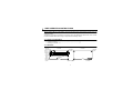
1
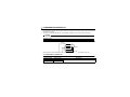
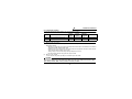
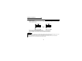
VECTOR INVERTER
VECTOR INVERTER
-INSTRUCTION MANUAL-
HIGH RESOLUTION ANALOG INPUT / EXTRA
CONTACT INPUT / THERMISTOR INTERFACE
FR-V5AX
HEAD OFFICE:MITSUBISHI DENKI BLDG MARUNOUCHI TOKYO 100-8310
IB(NA)-0600083-A (0110) MEE
Printed in Japan
Specifications subject to change without notice.
Thank you for choosing the Mitsubishi vector inverter option unit.
This instruction manual gives handling information and precautions for use of this equipment. Incorrect handling
might cause an unexpected fault. Before using the equipment, please read this manual carefully to use the equipment
to its optimum.
Please forward this manual to the end user.
This section is specifically about safety matters
Do not attempt to install, operate, maintain or inspect this product until you have read through this instruction manual and appended documents carefully and can use the equipment correctly. Do not use this product until you have
a full knowledge of the equipment, safety information and instructions.
In this instruction manual, the safety instruction levels are classified into "WARNING" and "CAUTION".
WARNING
Assumes that incorrect handling may cause hazardous conditions, resulting in
death or severe injury.
CAUTION
Assumes that incorrect handling may cause hazardous conditions, resulting in
medium or slight injury, or may cause physical damage only.
Note that the CAUTION level may lead to a serious consequence according to conditions. Please follow the instructions of both levels because they are important to personnel safety.
SAFETY INSTRUCTIONS
1. Electric Shock Prevention
WARNING
! While power is on or when the inverter is running, do not open the front cover. You may get an electric shock.
! Do not run the inverter with the front cover removed. Otherwise, you may access the exposed high-voltage terminals and charging part and get an electric shock.
power is off, do not remove the front cover except for wiring or periodic inspection. You may access the
charged inverter circuits and get an electric shock.
! Before starting wiring or inspection, switch power off, wait for more than 10 minutes, and check for no residual
voltage with a tester or the like.
! If
A-1
WARNING
! Any person who is involved in the wiring or inspection of this equipment should be fully competent to do the work.
! Always install the option unit before wiring. Otherwise, you may get an electric shock or be injured.
! Handle this option unit with dry hands to prevent an electric shock.
! Do not subject the cables to scratches, excessive stress, heavy loads or pinching. Otherwise, you may get an electric shock.
2. Injury Prevention
CAUTION
! Apply only the voltage specified in the instruction manual to each terminal to prevent burst, damage, etc.
! Ensure that the cables are connected to the correct terminals. Otherwise, burst, damage, etc. may occur.
! Always make sure that polarity is correct to prevent burst, damage, etc.
! While power is on or for some time after power-off, do not touch the inverter as it is hot and you may get burnt.
3. Additional instructions
Also note the following points to prevent an accidental failure, injury, electric shock, etc.:
(1) Transportation and mounting
CAUTION
! Do not install or operate the option unit if it is damaged or has parts missing.
! Do not stand or rest heavy objects on the product.
! Check that the mounting orientation is correct.
! Prevent screws, metal fragments or other conductive bodies or oil or other flammable substance from entering the inverter.
(2) Test operation and adjustment
CAUTION
! Before
starting operation, confirm and adjust the parameters. A failure to do so may cause some machines to
make unexpected motions.
A-2
(3) Usage
WARNING
! Do not modify the equipment.
CAUTION
! When parameter clear or all parameter clear is performed, each parameter returns to the factory setting. Re-set
the required parameters before starting operation.
! For prevention of damage due to static electricity, touch nearby metal before touching this product to eliminate
static electricity from your body.
(4) Maintenance, inspection and parts replacement
CAUTION
! Do not test the equipment with a megger (measure insulation resistance).
(5) Disposal
CAUTION
! Treat as industrial waste.
(6) General instruction
All illustrations given in this manual may have been drawn with covers or safety guards removed to provide indepth description. Before starting operation of the product, always return the covers and guards into original positions as specified and operate the equipment in accordance with the manual.
A-3
CONTENTS
1.PRE-OPERATION INSTRUCTIONS
1.1
1.2
1.3
Unpacking and Product Confirmation ..................................................................................................1
Packing Confirmation...........................................................................................................................1
Structure ..............................................................................................................................................1
2.INSTALLATION
2.1
2.2
2.3
10
Overview ............................................................................................................................................10
Explanation of terminals.....................................................................................................................10
Related Parameters ...........................................................................................................................11
Setting................................................................................................................................................11
Specifications.....................................................................................................................................12
5.THERMISTOR INTERFACE
5.1
5.2
5.3
5.4
5.5
5
Connection example ............................................................................................................................5
Explanation of terminals.......................................................................................................................5
Related parameters .............................................................................................................................6
Calibration............................................................................................................................................8
Noise reduction techniques..................................................................................................................9
Specifications.......................................................................................................................................9
4.EXTRA CONTACT INPUT FUNCTION
4.1
4.2
4.3
4.4
4.5
2
Pre-Installation Instructions..................................................................................................................2
Installation Procedure ..........................................................................................................................2
Wiring...................................................................................................................................................3
3.HIGH RESOLUTION ANALOG INPUT
3.1
3.2
3.3
3.4
3.5
3.6
1
13
Connection example ..........................................................................................................................13
Explanation of terminals.....................................................................................................................13
Parameter setting...............................................................................................................................14
Motor thermal relay alarm ..................................................................................................................14
Calibration..........................................................................................................................................15
1.PRE-OPERATION INSTRUCTIONS
1.1 Unpacking and Product Confirmation
Take the option unit out of the package, check the unit name, and confirm that the product is as you
ordered and intact.
This product is an option unit designed for exclusive use in the Mitsubishi FR-V500 series vector inverter.
Functions available differ, before using it, always make the following checks.
1.2 Packing Confirmation
Make sure that the package includes the following
" Instruction manual.........................................................................1
" Mounting screws M3 × 10 .............................................................2
1.3 Structure
Calibration
connector
(Refer to
page 15)
Mounting
hole
Terminal
block
screw
size M3
Terminal
symbol
Front view
Mounting
holes
Rear view
Mounting
hole
CON2
TH1 TH2 SD
6
5
DI11 DI12 DI13 DI14 DI15 DI16 PC2
FR-V5AX
Option fixing holes
1
Connector
2.INSTALLATION
2.1 Pre-Installation Instructions
Make sure that the input power of the inverter is off.
CAUTION
With input power on, do not install or remove the option unit. Otherwise, the inverter and
option unit may be damaged.
2.2 Installation Procedure
(1) Securely insert the connector of the option unit far into the connector of the inverter. At this time, fit the
option fixing holes snugly.
Also be sure to fit the unit into the option fixing hook.
(2) Securely fix the option unit to the inverter on both sides with the accessory mounting screws. If the
screw holes do not match, the connector may not have been plugged snugly. Check for loose plugging.
2
INSTALLATION
Option unit
Inverter
(without cover)
Accessory screw
(2 pcs.)
Slot 1
Option side
connector
Inverter side connector
Slot 2
Option fixing hook
Slot 3
The slots 1, 2, and 3 are provided
with an option fixing hook.
CAUTION
1. Only one type of option per inverter may be used. When two or more options are mounted, priority is in order of slots 1, 2 and 3, the options having lower priority are inoperative.
2. When the inverter cannot recognize that the option is
Mounting Position Error Display
mounted, it displays the option error. The errors shown
Slot 1
E.OP1
differ according to the mounting slots 1, 2, 3.
Slot 2
E.OP2
Slot 3
E.OP3
2.3 Wiring
Route the wires so that they do not take up a large space in the control circuit terminal block of the option unit.
During wiring, do not leave wire off-cuts in the inverter. They may cause a fault, failure or malfunction.
Use the space on the left side of the Control circuit terminal unit to route the wires.
3
INSTALLATION
Cable routing
REMARKS
The wires with large gaze may not be connected to the terminal block. When connected in parallel, all wires may not
fit in the wiring space due to the increased number of wires. In such cases, perform wiring by using a junction terminal block.
CAUTION
Do not use empty terminals as junction terminals because they are used in the option unit. If
they are used as the junction terminals, the option unit may be damaged.
When installing the inverter front cover, the cables to the inverter's control circuit terminals and
option terminals should be routed properly in the wiring space to prevent them from being
caught between the inverter and its cover.
4
3.HIGH RESOLUTION ANALOG INPUT
Speed command, torque command, speed retriction value and torque restriction value (same level for driving and regenerative modes) can be set using 0 to 10VDC analog voltage.
3.1 Connection example
+10V
FR-V5AX
6
-10V
5
3.2 Explanation of terminals
The high resolution analog input function uses the following terminals.
Terminal
symbol
Terminal name Rated current, etc.
6
High resolution
input terminal
Max. permissible
voltage 20VDC
5
Analog common
terminal
—
Description
0 to 10VDC input, high resolution (16-bit) analog voltage
input terminal. Select the terminal function using Pr. 406 " high
resolution analog input selection".
Common terminal for the No. 6 terminal.
5
HIGH RESOLUTION ANALOG INPUT
3.3 Related parameters
Set the high resolution analog input.
When Pr. 406 = "9999" (factory setting), "high resolution analog input selection" does not function.
Parameter
number
406
926
927
928
929
Name
Setting range
High resolution analog input selection
0, 2 to 5, 9999
No.6 terminal bias (speed)
0 to 10V, 0 to 3600r/min
No.6 terminal gain (speed)
0 to 10V, 0 to 3600r/min
No.6 terminal bias (torque)
0 to 10V, 0 to 400%
No.6 terminal gain (torque))
0 to 10V, 0 to 400%
Minimum setting
increments
Factory setting
1
0.1r/min
1r/min
0.1%
0.1%
9999
0V, 0r/min
10V, 1500r/min
0V, 0%
10V, 150%
REMAKS
For Pr.406, write is disabled during operation even when “2” is set in Pr.77. When changing the parameter setting,
stop the operation.
The Pr. 406 "high resolution analog input selection" setting and control modes are combined as indicated
in the following table.
Pr. 406
setting
No. 6 terminal No. 6 terminal No. 6 terminal
Bias/gain
function for
function for
function for
setting
speed control torque control position control
Remarks
0
Speed
command
Speed limit
No function
Pr. 926,
Pr. 927
Terminal 2 is made invalid and its functions
are replaced by terminal 6.
When Pr.868=0, terminal 1 acts as auxiliary.
2
Regenerative
mode torque
limit
No function
Regenerative
mode torque limit
Pr. 928,
Pr. 929
When Pr.868=2, terminal 1 is made invalid
and its functions are replaced by terminal 6.
6
HIGH RESOLUTION ANALOG INPUT
Pr. 406
setting
No. 6 terminal No. 6 terminal No. 6 terminal
Bias/gain
function for
function for
function for
setting
speed control torque control position control
3
No function
Torque
command
No function
Pr. 928,
Pr. 929
4
Torque limit
Torque
command
Torque limit
Pr. 928,
Pr. 929
5
No function (*)
Driving side
speed limit
No function
Pr. 926,
Pr. 927
9999
(factory
setting)
No function
No function
No function
Remarks
During torque control, terminal 3 is made invalid
and its functions are replaced by terminal 6.
During speed control and position control with
Pr.801=1 and torque control, terminal 3 is made
invalid and its functions are replaced by terminal 6.
Torque restriction level :Driving/regenration
are the same level:
When Pr.868=5, terminal 1 is made invalid and
its functions are replaced by terminal 6.
REMAKS
1. *:When performing driving side speed restriction, set "2" in Pr.807 "speed restriction selection".
The speed restriction value becomes Pr.1"maximum setting" when the driving side speed restriction is exercised.
2. The minimum resolution of the speed is 0.1r/min.
3. The setting of Pr. 822 "speed setting filter 1", Pr. 832 "speed setting filter 2", Pr. 826 "torque setting filter" or Pr.
836 "torque setting filter 2" is valid for the No. 6 terminal input.
For parameter details, refer to the Inverter Instruction Manual (detailed).
4. For details of terminals 1, 2, and 3, refer to inverter instruction manual (detailed).
7
HIGH RESOLUTION ANALOG INPUT
3.4 Calibration
(1) When Pr. 406 = 0 or 5 (speed setting), calibration is made as shown below.
Speed
Factory setting
(1500r/min)
Pr. 927
-10V
0
Pr. 926
10V
Input voltage
* When Pr. 406 = 5 (speed limit setting for torque control), the input from the No. 6 terminal is valid for
the driving mode only. It is invalid for the regenerative mode.
(2) When Pr. 406 = 2, 3 or 4 (torque command), calibration is made as shown below.
Output torque
(150%)
Pr. 929
-10V
0
Pr. 928
10V
Input voltage
(150%)
* When Pr. 406 = 2 (torque limit), the input from the No. 6 terminal is valid for the regenerative mode only.
8
HIGH RESOLUTION ANALOG INPUT
3.5 Noise reduction techniques
Use the following techniques if an analog signal is compounded with noise, resulting in instable operation.
(1) Techniques for wiring
1) Separate the power and signal cables as far as possible.
2) Use a twisted pair shield cable as the signal cable.
Handle the shield cable in any of the following ways.
• Connect it to the No. 5 terminal of the FR-V5AX.
• Connect it to the common terminal on the analog command device side.
• Connect it to both the No. 5 terminal of the FR-V5AX and the common terminal on the analog command device side.
• Connect it to neither the No. 5 terminal of the FR-V5AX nor the common terminal on the analog
command device side. (Keep the shield cable suspended.)
(2) Techniques on the inverter side
Decrease the setting of Pr. 72 "PWM frequency selection". (Motor-produced sound increases but inverter-generated noise reduces.)
Increase the settings of the speed (torque) setting filters, Pr. 822, Pr. 832 (Pr. 826, Pr. 836).
CAUTION
Changing the speed (torque) setting filter value affects the response level of the inverter to a command. Therefore, adjust it while simultaneously looking at the machine motion.
(3) Others
Install the FR-BLF line noise filter (FR-BSF01 for 3.7K or less).
Reinforce or separate earthing.
3.6 Specifications
Resolution
Input resistance
Max. input voltage
0.003% at 0 to 10V input (16 bits)
14kΩ
20V
9
4.EXTRA CONTACT INPUT FUNCTION
4.1 Overview
Six terminal input points can be added by assigning functions to the DI11 to DI16 input terminals using Pr.
400 to Pr. 405 (input terminal function selection). At this time, since five more points can be chosen with Pr.
180 to Pr. 183 and Pr. 187 "input terminal assignment" of the inverter, a total of 11 input terminals are available. The signal from the 6 bit data (binary) input terminal can be used as external position command during position control.
4.2 Explanation of terminals
This extra contact input function uses the following terminals.
Terminal
symbol
PC2
Terminal name
Description
External transistor When connecting the transistor output (open collector output) of a programmable controller (PC) or like, connecting the external power supply common for transistor output
common
to this terminal prevents a malfunction caused by a sneak current.
DI11
DI12
DI13
DI14
DI15
DI16
Multi-function
input terminal
SD
Contact input
common
•Set function assignment in Pr. 400 to Pr. 405 (input terminal function selection).
•Input the binary 6 bit signal during position control.
bit
terminal
b5
b4
b3
b2
b1
b0
DI16
DI15
DI14
DI13
DI12
DI11
Contact input common terminal. Do not connect this terminal with the other common
terminal. Do not earth (ground) this terminal.
10
EXTRA CONTACT INPUT FUNCTION
4.3 Related Parameters
The functions of the DI11 to DI16 input terminals can be assigned using Pr. 400 to Pr. 405 (input terminal
function selection).
Parameter
number
400
401
402
403
404
405
Name
DI11 terminal function selection
DI12 terminal function selection
DI13 terminal function selection
DI14 terminal function selection
DI15 terminal function selection
DI16 terminal function selection
Factory setting
Setting range
Minimum setting
increments
9999
9999
9999
9999
9999
9999
0 to 99, 9999
0 to 99, 9999
0 to 99, 9999
0 to 99, 9999
0 to 99, 9999
0 to 99, 9999
1
1
1
1
1
1
REMAKS
For Pr.400 to Pr.406, write is disabled during operation even when “2” is set in Pr.77. When changing the parameter
setting, stop the operation.
4.4 Setting
The Pr.400 to Pr.405 "input terminal function selection" settings are the same as Pr.180 to Pr.183 and Pr.187
"input terminal function selection". Note that the X10 signal can not be assigned to the FR-V5AX.
When using the X10 signal, assign it to the input terminals DI1 to DI4 of the inverter.
Refer to the instruction manual of the inverter for parameter details.
11
EXTRA CONTACT INPUT FUNCTION
4.5 Specifications
• Input signal types
Select a signal from among the low-speed operation command, mid-speed operation command, highspeed operation command, remote setting, second function selection, jog operation selection, 15speed selection, third function selection, FR-HC connection (instantaneous power failure detection),
PU operation external interlock, external DC braking start, PID control enable terminal, brake opening
completion signal, PU operation-external operation switch-over, S-pattern acceleration/deceleration C
switching terminal, orientation command, pre-excitation/servo on, output stop, start self-holding selection, control mode changing, torque limit selection, torque bias selection 1, torque bias selection 2 and
P control selection (P/PI control switching).
• Input signal selection ......... Use Pr. 400 to Pr. 405 to make selection.
• Input terminal selection ...... Open collector output or no-voltage contact signal
12
5.THERMISTOR INTERFACE
When the vector inverter motor with a thermistor (SF-V5R) is used, the motor temperature detected by the
thermistor in the motor can be fed back to the inverter to reduce the fluctuation of generated torque caused
by temperature change.
The rauge or motor temperature that can be detected is between -50°C to 200°C (-58°F to 392°F).
CAUTION
To detect temperatures at the FR-V5AX, always use the SF-V5R vector inverter motor provided
with thermistor.
5.1 Connection example
Inverter
U
IM
V
W
Thermistor
FR-V5AX
TH1
TH2
Twisted pair shield cable
Change jumpers of the thermistor calibration connecter to use the themistor. (Refer to page 15)
5.2 Explanation of terminals
This extra contact input function uses the following terminals.
Terminal symbol
TH1
TH2
Terminal name
Thermistor input 1
Thermistor input 2
Description
A motor side thermistor output signal is input.
13
THERMISTOR INTERFACE
5.3 Parameter setting
The following parameters are provided for use of the thermistor interface.
Parameter
Name
Factory
setting
Setting
range
Minimum
input
increments
407
925
Motor temperature detection filter
Motor temperature detection calibration
9999
100%
0 to 100s, 9999
0 to 200%
1s
0.1%
Remarks
9999: No function
5.4 Motor thermal relay alarm
(1) When Pr. 407 = "0 to 100"
Normally, set 30s in Pr. 407. If the response level to a motor temperature is low, make adjustment to
decrease the setting.
• Detection of a 145°C (293°F) or higher motor temperature continuously for 10s results in a motor thermal
relay alarm (E.THM), shutting off the output.
• Detection of a -30°C (-22°F) or lower motor temperature during operation results in a motor thermal
relay alarm (E.THM), shutting off the output.
During a stop, a motor thermal relay alarm (E.THM) does not occur.
• The OH terminal (thermal relay protector input) is invalid.
(2) When Pr. 407 = "9999"
A motor thermal relay alarm (E.THM) is not detected by the FR-V5AX.
CAUTION
The vector inverter motor with thermistor does not have a thermal relay protector. When using this
type of motor, always set a value other than "9999" in Pr. 407 "motor temperature detection filter".
If the setting remains "9999", motor protection cannot be provided.
14
THERMISTOR INTERFACE
5.5 Calibration
Calibrate the inverter and FR-V5AX (thermistor interface). Always calibrate them at the time of installation.
(1) Calibration method
1) Remove the jumper from the lower pin of CON2 and insert it into the upper pin to choose the thermistor calibration status.
CON2
TH1
TH2
SD
CON2
6
5
TH1
TH2
SD
6
5
2) Read Pr. 925 and set a compensation value.
(For the setting method of the compensation value, refer to page 16.)
3) After completion of compensation, return the jumper to the lower pin.
REMAKS
If you start the motor in the thermistor calibration status (with the jumper of CON2 inserted in the upper pin), a motor
thermal relay alarm (E.THM) will occur in 10 seconds and the inverter output is shut off.
Likewise, if you start the motor without the thermistor interface being connected, a motor thermal relay alarm
(E.THM) will occur in 10 seconds and the inverter output is shut off.
15
THERMISTOR INTERFACE
(2) Operation procedure for compensation value setting
•For FR-DU04-1
FR-DU04-1
CONTROL PANEL
Hz
A
V
MON
EXT
PU
REV
FWD
Press
FR-DU04-1
SET
.
CONTROL PANEL
Hz
A
V
MON
EXT
PU
REV
FWD
Press
FR-DU04-1
for 1.5s.
Current compensation command value
(Compensation value is calculated)
Hz
A
V
MON
SET
CONTROL PANEL
EXT
PU
REV
FWD
When adjusting the compensation value arbitrarily
Press SET for 1.5s.
(Current compensation
value is written.)
FR-DU04-1
Hz
A
V
EXT
PU
REV
FWD
MON
EXT
PU
REV
FWD
Current compensation setting
(Currently used compensation value)
Press
FR-DU04-1
"99.5" flickers and the com
pensation value is set to "99.5".
once.
CONTROL PANEL
CONTROL PANEL
Hz
A
V
MON
Press
FR-DU04-1
once.
CONTROL PANEL
Hz
A
V
MON
EXT
REV
PU
FWD
Press
FR-DU04-1
Hz
A
V
MON
SET
for 1.5s.
CONTROL PANEL
EXT
PU
REV
FWD
16
"99.8" flickers and the compensation
value is set to "99.8".Press for 1.5s.
THERMISTOR INTERFACE
•For FR-PU04V
<SETTING MODE>
Set Pr. NO
925
<READ>
Press
READ
.
Press
READ
.
925
Set
EXT
0.00
<WRITE>
<READ>
Currently used compensation value
925
0.00
99.5%
99.0%
EXT
Current compensation setting
Current compensation command value
Press
WRITE .
Compensation value is calculated on the inverter side.
925
0.00
99.5%
99.0%
EXT
When adjusting the compensation value arbitrarily
Press
WRITE
Enter 99.2.Press .
.
(Current compensation
value is written.)
925
0.00
99.2%
99.0%
EXT
925
0.00
99.0%
Completed
(Compensation value
is set to 99.0%.)
Press
WRITE .
925
0.00
99.2%
Completed
17
(Compensation value
is set to 99.2%.)
REVISIONS
*The manual number is given on the bottom left of the back cover.
Print Date
*Manual Number
Oct., 2001
IB(NA)-0600083-A
Revision
First edition