1
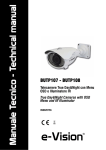
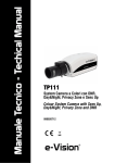
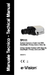
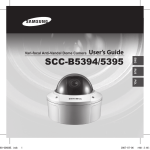
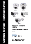
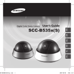
Manuale Tecnico - Technical Manual
VDH40
Dome Antivandalo a Colori ad Alta
Risoluzione con Illuminatore IR
Colour High-Resolution Vandal-proof
Dome Camera with IR Illuminator
090020828
Manuale Tecnico - VDH40 - 090020828 - Technical Manual
AVVERTENZE - FOREWORD
PER L’INSTALLATORE: Attenersi scrupolosamente alle normative vigenti sulla realizzazione di impianti elettrici e sistemi di sicurezza, oltre che alle prescrizioni del costruttore
riportate nella manualistica a corredo dei prodotti.
Fornire all’utilizzatore tutte le indicazioni sull’uso e sulle limitazioni del sistema installato, specificando che esistono norme specifiche e diversi livelli di prestazioni di sicurezza
che devono essere commisurati alle esigenze dell’utilizzatore.
Far prendere visione all’utilizzatore delle avvertenze riportate in questo documento.
PER L’UTILIZZATORE: Verificare periodicamente e scrupolosamente la funzionalità dell’impianto accertandosi della correttezza dell’esecuzione delle manovre di inserimento
e disinserimento. Curare la manutenzione periodica dell’impianto affidandola a personale specializzato in possesso dei requisiti prescritti dalle norme vigenti. Provvedere a
richiedere al proprio installatore la verifica dell’adeguatezza dell’impianto al mutare delle condizioni operative (es. variazioni delle aree da proteggere per estensione, cambiamento
delle metodiche di accesso ecc...)
Questo dispositivo è stato progettato, costruito e collaudato con la massima cura, adottando procedure di controllo in conformità alle normative vigenti. La piena rispondenza
delle caratteristiche funzionali è conseguita solo nel caso di un suo utilizzo esclusivamente limitato alla funzione per la quale è stato realizzato, e cioè:
Dome Antivandalo a Colori ad Alta Risoluzione con Illuminatore IR - VDH40
Qualunque utilizzo al di fuori di questo ambito non è previsto e quindi non è possibile garantire la sua corretta operatività e pertanto è fatto espresso divieto al detentore del
presente manuale di utilizzarlo per ragioni diverse da quelle per le quali é stato redatto ovvero esplicative delle caratteristiche tecniche del prodotto e delle modalità di uso.
I processi produttivi sono sorvegliati attentamente per prevenire difettosità e malfunzionamenti; purtuttavia la componentistica adottata è soggetta a guasti in percentuali
estremamente modeste, come d’altra parte avviene per ogni manufatto elettronico o meccanico. Vista la destinazione di questo articolo (protezione di beni e persone) invitiamo
l’utilizzatore a commisurare il livello di protezione offerto dal sistema all’effettiva situazione di rischio (valutando la possibilità che detto sistema si trovi ad operare in modalità
degradata a causa di situazioni di guasti od altro), ricordando che esistono norme precise per la progettazione e la realizzazione degli impianti destinati a questo tipo di applicazioni.
Richiamiamo l’attenzione dell’utilizzatore (conduttore dell’impianto) sulla necessità di provvedere regolarmente ad una manutenzione periodica del sistema almeno
secondo quanto previsto dalle norme in vigore oltre che ad effettuare, con frequenza adeguata alla condizione di rischio, verifiche sulla corretta funzionalità del sistema
stesso segnatamente alla centrale, sensori, avvisatori acustici, combinatore/i telefonico/i ed ogni altro dispositivo collegato. Al termine del periodico controllo l’utilizzatore
deve informare tempestivamente l’installatore sulla funzionalità riscontrata.
La progettazione, l’installazione e la manutenzione di sistemi incorporanti questo prodotto sono riservate a personale in possesso dei requisiti e delle conoscenze necessarie
ad operare in condizioni sicure ai fini della prevenzione infortunistica. E’ indispensabile che la loro installazione sia effettuata in ottemperanza alle norme vigenti. Le parti interne
di alcune apparecchiature sono collegate alla rete elettrica e quindi sussiste il rischio di folgorazione nel caso in cui si effettuino operazioni di manutenzione al loro interno prima
di aver disconnesso l’alimentazione primaria e di emergenza. Alcuni prodotti incorporano batterie ricaricabili o meno per l’alimentazione di emergenza. Errori nel loro collegamento
possono causare danni al prodotto, danni a cose e pericolo per l’incolumità dell’operatore (scoppio ed incendio).
FOR THE INSTALLER:
Please follow carefully the specifications relative to electric and security systems realization further to the manufacturer’s prescriptions indicated in the manual provided.
Provide the user the necessary indication for use and system’s limitations, specifying that there exist precise specifications and different safety performances levels that should
be proportioned to the user needs. Have the user view the directions indicated in this document.
FOR THE USER:
Periodically check carefully the system functionality making sure all enabling and disabling operations were made correctly.
Have skilled personnel make the periodic system’s maintenance. Contact the installer to verify correct system operation in case its conditions have changed (e.g.: variations
in the areas to protect due to extension, change of the access modes, etc…)
This device has been projected, assembled and tested with the maximum care, adopting control procedures in accordance with the laws in force. The full correspondence to
the functional characteristics is given exclusively when it is used for the purpose it was projected for, which is as follows:
VDH40 Colour High-Resolution Vandal-proof Dome Camera with IR Illuminator
Any use other than the one mentioned above has not been forecasted and therefore it is not possible to guarantee the correct functioning of the device. Similarly, any other
use of this technical manual other than the one it has been compiled for - that is: to illustrate the devices technical features and operating mode - is expressly prohibited.
The manufacturing process is carefully controlled in order to prevent defaults and bad functioning. Nevertheless, an extremely low percentage of the components used is
subjected to faults just as any other electronic or mechanic product. As this item is meant to protect both property and people, we invite the user to proportion the level of
protection that the system offers to the actual risk (also taking into account the possibility that the system was operated in a degraded manner because of faults and the like),
as well reminding that there are precise laws for the design and assemblage of the systems destinated to these kind of applications.
The system’s operator is hereby advised to see regularly to the periodic maintenance of the system, at least in accordance with the provisions of current legislation,
as well as to carry out checks on the correct running of said system on as regular a basis as the risk involved requires, with particular reference to the control unit,
sensors, sounders, dialler(s) and any other device connected. The user must let the installer know how well the system seems to be operating, based on the results
of periodic checks, without delay.
Design, installation and servicing of systems which include this product, should be made by skilled staff with the necessary knowledge to operate in safe conditions in order
to prevent accidents. These systems’ installation must be made in accordance with the laws in force. Some equipment’s inner parts are connected to electric main and therefore electrocution may occur if servicing was made before switching off the main and emergency power. Some products incorporate rechargeable or non rechargeable
batteries as emergency power supply. Their wrong connection may damage the product, properties and the operator’s safety (burst and fire).
Timbro della ditta installatrice - Your dealer/installer:
2
Manuale Tecnico - VDH40 - 090020828 - Technical Manual
INDICE
CONTENTS
1. GENERALITA’ . . . . . . . . . . . . . . . . . . . . . . . . . . . . . . . . . . . . . . . . . 5
2. CARATTERISTICHE TECNICHE . . . . . . . . . . . . . . . . . . . . . . . . . . . . 5
3. VISTA DELLA TELECAMERA . . . . . . . . . . . . . . . . . . . . . . . . . . . . . . 6
4. SCHEMA DI COLLEGAMENTO . . . . . . . . . . . . . . . . . . . . . . . . . . . . 7
5. INSTALLAZIONE . . . . . . . . . . . . . . . . . . . . . . . . . . . . . . . . . . . . . . . 7
5.1.Posizioni corrette . . . . . . . . . . . . . . . . . . . . . . . . . . . . . . . . . . . .9
5.2.Procedura di installazione . . . . . . . . . . . . . . . . . . . . . . . . . . . .11
6. CONTROLLO MENU OSD . . . . . . . . . . . . . . . . . . . . . . . . . . . . . . . 15
7. SETTAGGI CONSIGLIATI . . . . . . . . . . . . . . . . . . . . . . . . . . . . . . . . 16
8. MENU OSD . . . . . . . . . . . . . . . . . . . . . . . . . . . . . . . . . . . . . . . . . . 17
8.1.Menu LENS . . . . . . . . . . . . . . . . . . . . . . . . . . . . . . . . . . . . . . .17
8.2.Menu EXPOSURE . . . . . . . . . . . . . . . . . . . . . . . . . . . . . . . . . . .18
8.3.Menu WHITE BALANCE . . . . . . . . . . . . . . . . . . . . . . . . . . . . . .19
8.4.Menu DAY / NIGHT . . . . . . . . . . . . . . . . . . . . . . . . . . . . . . . . . .21
8.5.Menu PICTURE ADJUST . . . . . . . . . . . . . . . . . . . . . . . . . . . . . .23
8.6.Menu Digital Wide Dynamic Range . . . . . . . . . . . . . . . . . . . . .24
8.7.Menu HLC /BLC . . . . . . . . . . . . . . . . . . . . . . . . . . . . . . . . . . . .25
8.8.Menu PRIVACY . . . . . . . . . . . . . . . . . . . . . . . . . . . . . . . . . . . . .26
8.9.Menu MOTION DETECTION . . . . . . . . . . . . . . . . . . . . . . . . . . . .28
8.10.Menu CAMERA SETUP . . . . . . . . . . . . . . . . . . . . . . . . . . . . . .30
9. AVVERTENZE PER LO SMALTIMENTO . . . . . . . . . . . . . . . . . . . . . 32
1. GENERALS . . . . . . . . . . . . . . . . . . . . . . . . . . . . . . . . . . . . . . . . . . . 5
2. TECHNICAL SPECIFICATIONS . . . . . . . . . . . . . . . . . . . . . . . . . . . . . 5
3. CAMERA VIEW . . . . . . . . . . . . . . . . . . . . . . . . . . . . . . . . . . . . . . . . 6
4. WIRING DIAGRAM . . . . . . . . . . . . . . . . . . . . . . . . . . . . . . . . . . . . . 7
5. INSTALLATION . . . . . . . . . . . . . . . . . . . . . . . . . . . . . . . . . . . . . . . . 7
5.1.Correct positions . . . . . . . . . . . . . . . . . . . . . . . . . . . . . . . . . . . 8
5.2.Installation steps . . . . . . . . . . . . . . . . . . . . . . . . . . . . . . . . . . 10
6. OSD MENU CONTROL . . . . . . . . . . . . . . . . . . . . . . . . . . . . . . . . . . 14
7. RECOMMENDED SETUP . . . . . . . . . . . . . . . . . . . . . . . . . . . . . . . . 15
8. OSD MENU . . . . . . . . . . . . . . . . . . . . . . . . . . . . . . . . . . . . . . . . . . 16
8.1.LENS Menu . . . . . . . . . . . . . . . . . . . . . . . . . . . . . . . . . . . . . . . 16
8.2.EXPOSURE Menu . . . . . . . . . . . . . . . . . . . . . . . . . . . . . . . . . . 17
8.3.WHITE BALANCE Menu . . . . . . . . . . . . . . . . . . . . . . . . . . . . . . 18
8.4.DAY / NIGHT Menu . . . . . . . . . . . . . . . . . . . . . . . . . . . . . . . . . 20
8.5.PICTURE ADJUST Menu . . . . . . . . . . . . . . . . . . . . . . . . . . . . . 22
8.6.Digital WDR Menu . . . . . . . . . . . . . . . . . . . . . . . . . . . . . . . . . 23
8.7.HLC /BLC Menu . . . . . . . . . . . . . . . . . . . . . . . . . . . . . . . . . . . 24
8.8.PRIVACY Menu . . . . . . . . . . . . . . . . . . . . . . . . . . . . . . . . . . . . 25
8.9.MOTION DETECTION Menu . . . . . . . . . . . . . . . . . . . . . . . . . . . 27
8.10.CAMERA SETUP Menu . . . . . . . . . . . . . . . . . . . . . . . . . . . . . 29
9. DISPOSAL INSTRUCTIONS . . . . . . . . . . . . . . . . . . . . . . . . . . . . . . 31
3
Manuale Tecnico - VDH40 - 090020828 - Technical Manual
Pagina bianca
Blank page
4
Manuale Tecnico - VDH40 - 090020828 - Technical Manual
1. GENERALITA’
1. GENERALS
Leggere attentamente le istruzioni prima dell’uso.
VDH40 è una telecamera avanzata adatta per vari ambienti installativi. L'immagine delle telecamere è composta da 700 linee TV che garantiscono un' elevata risoluzione del sensore
CCD. La telecamera è dotata di un filtro meccanico IR, garanzia di ottime riprese in qualsiasi condizione di luce. Ulteriori caratteristiche avanzate: 3DNR, HLC, Sens-Up e DWDR.
Please review carefully instructions before use.
VDH40 is an advanced camera suitable for various installation
environments. It features 700 TV lines ensuring CCD high resolution for clearer and detailed images. The camera is equipped with an IR mechanical filter that ensures excellent
recordings under all light conditions. It features advanced characteristics such as 3DNR, HLC, Sens-Up, and DWDR.
2. CARATTERISTICHE TECNICHE
2. TECHNICAL SPECIFICATIONS
Modello:
Standard:
Sensore:
Elementi sensibili:
Sistema di scansione:
Sistema di sincronizz.:
Risoluzione orizz.:
Rapporto S/N:
OSD:
Segnale uscita video:
Illuminazione minima:
Model:
Standard TV:
Image sensor:
Total pixels:
Scanning system:
Synchronization system:
H-Resolution:
S/N Ratio:
OSD:
Video output signal:
Minimum illumination:
VDH40
PAL
1/3" Sony EX-View HAD II CCD
976 (H) x 582 (V) PAL
2:1 interlacciato
Interna / Auto
700 linee TV
>52dB (AGC OFF)
incorporato
1.0 Vpp, 75Ohm (BNC)
IR LED ON: 0Lux
IR LED OFF: [email protected] (colore)
IR LED OFF: 0.00009Lux (B/N)
Ottica:
2.8-12mm AUTOIRIS
Funzione Day&Night:
True Day&Night
IR Cut Filter:
SI’
Otturatore elettronico:
AUTO / 1/50 - 1/100.000 s
Fr. di scansione:
H:15,625 KHz - V:50Hz
Funzione DWDR:
OFF / ON (5 step)
Bilan. del bianco:
ATW - PUSH LOCK - MANUAL - ANTI-CR
USER1, USER2, PUSH
Funz. 3DNR:
regolabile ( 0 - 5 )
Controllo AGC:
Regolabile (8 step)
Comp. controluce:
HLC / BLC
Funz. Day&Night:
EXT ON - AUTO - COLOR - B/W
Controllo led IR:
a fotoresistenza (CDS)
Lunghezza d’onda IR:
850nm
IR Led:
18 LED
Portata IR:
15m
Potenza IR:
regolabile con trimmer
SMART IR:
SI’
Sens Up:
SI’
Funzione DPC:
SI’
Uscita monitor:
uscita monitor secondario per taratura
Rilevaz. Motion:
OFF / ON ( 4 zone)
Mascheramento:
OFF / ON ( 8 zone)
Funzione Mirror:
OFF / H-FLIP / V-FLIP / H+V-FLIP
Regolazione Immagine:
Nitidezza, Mirror, Contrasto, DNR
Zoom Digitale:
0 - 255
Correzione Gamma:
0,45
Modalità display:
CRT / LCD
Lens:
Day&Night function:
IR Cut Filter:
Electronic Shutter:
Scanning Frequency:
DWDR:
White Balance:
3DNR function:
AGC:
Back light comp.:
Day&Night:
IR Led Controls:
IR Wavelenght:
IR Led:
IR Distance:
IR Intensity:
SMART IR:
Sens Up:
DPC function:
Monitor output:
Motion Detection:
Privacy Mask:
Mirror Function:
Image adjustment:
Digital Zoom:
Gamma correction:
Display mode:
5
VDH40
PAL
1/3" Sony EX-View HAD II CCD
976 (H) x 582 (V) PAL
2:1 interlaced
Internal / Auto
700 TV lines
>52dB (AGC OFF)
built in
1.0 Vpp, 75Ohm (BNC)
IR LED ON: 0Lux
IR LED OFF: [email protected] (color)
IR LED OFF: 0.00009Lux (B/W)
2.8-12mm AUTOIRIS
True Day&Night
YES
AUTO / 1/50 - 1/100.000 s
H:15.625 KHz - V:50Hz
OFF / ON (5 steps)
ATW - PUSH LOCK - MANUAL - ANTI-CR
USER1, USER2, PUSH
adjustable ( 0 - 5 )
Adjustable (8 steps)
HLC / BLC
EXT ON - AUTO - COLOR - B/W
Photo resistor (CDS)
850nm
18 LEDs
15m
adjustable with trimmer
YES
YES
YES
spot monitor output for calibration
OFF / ON ( 4 areas)
OFF / ON ( 8 areas )
OFF / H-FLIP / V-FLIP / H+V-FLIP
Sharpness, Mirror, Contrast, DNR
0 - 255
0,45
CRT / LCD
Manuale Tecnico - VDH40 - 090020828 - Technical Manual
Custodia:
Grado di protezione:
Alimentazione:
Assorbimento:
Dimensioni:
Peso:
Condizioni operative:
Dotazione:
Accessori:
Lega di alluminio con passaggio cavi
all’interno della staffa
IP66
12Vcc/24Vca +/-10%
350mA @ 12Vcc (8,5W)
Diametro 149 x H 109 mm
920g
-20°C : +50°C - 95% UR
adattatore di alimentazione, dima di foratura,
viti e tasselli di fissaggio, guarnizione, foglio
tecnico
MDV WM : staffa per montaggio a palo
Housing:
Protection class:
Power supply:
Power consumption:
Dimensions:
Weight:
Operation Temperature:
Parts supplied:
Optional parts:
Alluminium alloy with full cable
management
IP66
DC12V / AC24V +/-10%
350mA@DC12V (8,5W)
Diameter 149 x H 109 mm
920g
-20°C : +50°C - RH 95%
drilling template, screws and dowels, rubber
gasket, power supply adapter, technical sheet
MDV WM : pole mount collar
La portata dell'illuminatore all'interno in condizioni ideali è di
15m. Per qualsiasi tipo di applicazioni in esterno, la portata
dell'illuminatore varia e deve essere valutata volta per volta in
base al soggetto da inquadrare e alle condizioni ambientali del
luogo di ripresa.
IR illuminator range for indoor installations is 15m under ideal
conditions.
For outdoor installations, illuminator range may differ and
has to be estimated considering the object to monitor and environment conditions.
NOTA: attenzione se la scena da riprendere è priva di qualsiasi
tipo di riflessione e in totale assenza di luce, la portata dell'illuminatore diminuisce del 60%.
NOTE: if the scene to shoot is completely devoid of light or reflection surfaces (walls), illuminator range will be reduced by
60%.
3. VISTA DELLA TELECAMERA
3. CAMERA VIEW
6
Manuale Tecnico - VDH40 - 090020828 - Technical Manual
4. SCHEMA DI COLLEGAMENTO
4. WIRING DIAGRAM
52cm
LUNGHEZZA DEL CAVO
CABLE LENGHT
ADATTATORE FORNITO
ADAPTER SUPPLIED
UTILIZZABILE ANCHE PER
ALIMENTAZIONE A 24VAC
SUITABLE ALSO FOR
24VAC POWER SUPPLY
SCHERMO DELLA
TELECAMERA
CAMERA
SHIELD
OBIETTIVO
VIDEO OUTPUT
75 OHM
DC IN
FOTORESISTENZA
PER COMMUTAZIONE
COLORE / BN
LENS
PHOTO-RESISTOR
FOR COLOUR / BW
AUTOMATIC SWITCH
24V 50Hz
AC IN
12V +/-10%
ALIMENTAZIONE
POWER SUPPLY
ESEMPIO/ EXAMPLE
MOD. TLC/ALVS2
(ALI38002 )
5. INSTALLAZIONE
5. INSTALLATION
Nella scelta del punto di fissaggio è da tenere in particolare
considerazione la struttura della cupola e la sua resa ottica per
evitare distorsioni o aberrazioni. Nella figura seguente sono
evidenziate le inclinazioni suggerite:
Wheh choosing the position, please consider the dome shape
and the optical range carefully in order to avoid images distortion or alteration. The following image shows tilt angle recommended:
DISTORTED
IMAGES
DISTORTED
IMAGES
IMAGES WITH
LOW DISTORSION
IMAGES WITH
LOW DISTORSION
BEST IMAGES
LENS AXIS
7
Manuale Tecnico - VDH40 - 090020828 - Technical Manual
Prima di rimontare la cupola è necessario fare attenzione al
posizionamento corretto del gommino di protezione dell’ottica
affinchè sia correttamente in sede.
Before mounting the dome back in place, make sure the lens
protection gasket is positioned correctly.
In particolari condizioni installative, quando l’inclinazione è
alquanto allineata alla parete è necessario intervenire sulla
fila di led che risultassero coperti dal bordo della base. In
questo frangente la luce IR emessa è riflessa dalla base
stessa andando ad altreare la ripresa.
In questo caso è necessario coprire il gruppo di led con un
pezzo di nastro nero da elettricisti.
La portata risultante del fascio IR sarà ovviamente ridotta.
In some special cases, when the camera tilt angle is rather
aligned to the wall, it may be necessary to adjust the LED
indicators line masked by the base edge. In such cases, the
IR light emitted is reflected by the very base and will alter
the images shot.
To avoid such alteration, make sure the LED indicators are
covered with electrical black tape.
As a consequence, IR beam range will be reduced.
8
Manuale Tecnico - VDH40 - 090020828 - Technical Manual
5.1 Posizioni corrette
5.1 Correct positions
Per l’installazione della telecamera seguire attentamente le
istruzioni illustrate negli schemi riportati di seguito.
For camera installation, follow instructions illustrated in the
diagrams below thoroughly.
Nota: il grado IP indicato nella documentazione del prodotto si
riferisce solo ed esclusivamente ad una installazione
eseguita nel modo corretto.
Note: IP class indicated in the product documentation refers
exclusively to the product installed correctly.
5.1.1 Esempio di installazione riparata
5.1.1 Example of a sheltered installation
Le righe tratteggiate indicano solo l’orientamento ipotetico della telecamera non l’angolo di ripresa.
Dotted lines of the image indicates a possible orientation of the
camera and NOT the correct shooting angle.
Possibili soluzioni corrette di installazione:
Example of correct positions for camera installation:
9
Manuale Tecnico - VDH40 - 090020828 - Technical Manual
Soluzioni non corrette di installazione.
Example of wrong positions for camera installation:
5.1.2 Esempio di installazione non riparata
5.1.2 Example of a non-sheltered installation
Le righe tratteggiate indicano solo l’orientamento ipotetico della telecamera non l’angolo di ripresa.
Dotted lines of the image indicates a possible orientation of the
camera and NOT the correct shooting angle.
Possibili soluzioni corrette di installazione:
Example of correct positions for camera installation:
10
Manuale Tecnico - VDH40 - 090020828 - Technical Manual
Soluzioni non corrette di installazione:
Example of wrong positions for camera installation:
5.2 Procedura di installazione
5.2 Installation steps
•STEP 1
•STEP 1
Eseguire i fori in base alla dima di foratura fornita con il prodotto:
Drill installation holes according to the drilling template provided:
•STEP 2
•STEP 2
Rimuovere la cupola trasparente della telecamera svitando le
viti di fissaggio con un cacciavite appropriato:
Remove camera transparent dome: unscrew the fixing screws
with a suitable screwdriver:
11
Manuale Tecnico - VDH40 - 090020828 - Technical Manual
•STEP 3
•STEP 3
Effettuare le regolazioni dei tre assi della telecamera agendo
sul corpo della stessa come indicato dalla frecce:
Adjust camera’s 3 axis by moving camera controls as indicated by the arrows
•STEP 4
•STEP 4
Rimuovere la pellicola protettiva della telecamera.
Remove protective film of the camera.
12
Manuale Tecnico - VDH40 - 090020828 - Technical Manual
•STEP 5
•STEP 5
Aprire lo sportellino frontale con uno strumento adatto:
Open the small front door with a suitable tool:
•STEP 6
•STEP 6
Regolare zoom e fuoco della telecamera.
-- AGIRE CON ESTREMA DELICATEZZA -Utilizzare un cacciavite appropriato per le viti di regolazione di zoom e focus
Adjust camera zoom and focus.
HANDLE THE CAMERA WITH THE UTMOST CARE!
Use a suitable screwdriver to adjust zoom and focus screws!
Una volta terminate le regolazioni, richiudere lo sportello frontale.
Once zoom and focus are adjusted properly, close the small
front door.
13
Manuale Tecnico - VDH40 - 090020828 - Technical Manual
•STEP 7
•STEP 7
Rimontare la cupola della telecamera:
Put the transparent dome back in place:
•STEP 8
•STEP 8
Vista fondo telecamera.
Prima di fissare la telecamera al muro installare correttamente
la guarnizione:
View of camera base.
Before installing tha camera on to the wall, mount the gasket
properly:
Esempio di cavo posizionato correttamente.
Example of cable positioned correctly.
14
Manuale Tecnico - VDH40 - 090020828 - Technical Manual
6. CONTROLLO MENU OSD
6. OSD MENU CONTROL
Utilizzare il tasto indicato dalla freccia per:
- accedere al menu principale
- accedere agli altri menu/sottomenu
- selezionare un’opzione
Use the button indicated by the arrow to:
- enter the main menu
- enter other menus
- select a menu option
Muovere il tasto SU / GIU’ per:
- navigare tra menu e opzioni in senso verticale
Move the button UP / DOWN:
- to browse menus and options vertically
Muovere il tasto verso DESTRA / SINISTRA per:
- navigare tra menu e opzioni in senso orizzontale
Move the button LEFT / RIGHT:
- to browse menus and options horizontally
Il simbolo
accanto ad una voce di menu indica la presenza di un sottomenu per quell’opzione.
A sign
menu.
Per entrare nel menu, premere il tasto.
Per uscire dal menu, selezionare RETURN nel menu OSD.
To enter the submenu, press the button.
To exit a menu/submenu, select RETURN in the OSD menu.
15
next to an item menu indicates an available sub-
Manuale Tecnico - VDH40 - 090020828 - Technical Manual
7. SETTAGGI CONSIGLIATI
7. RECOMMENDED SETUP
Al fine di ottenere il miglior COMPROMESSO tra la visione
diurna (DAY) e la visione notturna (NIGHT), si raccomanda di
impostare i seguenti parametri:
In order to obtain the best COMPROMISE between DAY vision
and NIGHT vision, it is strongly recommended to set the following parameters:
- nel menu EXPOSURE:
- in EXPOSURE menu:
- nel menu PICTURE ADJUST > DNR:
- in PICTURE ADJUST > DNR menu:
Se si desidera aumentare il livello di sensibilità delle telecamera per la visione NOTTURNA agire nel menu:
In order to increase the camera sensitivity level for NIGHT vision, please go to
EXPOSURE > LOW LUMINANCE > BRIGHTNESS
EXPOSURE > LOW LUMINANCE > BRIGHTNESS
e impostare un valore superiore a 0,25.
menu and set a value above 0,25.
Inoltre è possibile migliorare la riduzione del rumore aumentando il livello impostato nel menu:
In addition it is possible to improve noise reduction by increasing the level in the menu:
PICTURE ADJUST > DNR
PICTURE ADJUST > DNR
L’aumento del livello del DNR non è consigliato nel caso di
immagini in movimento.
The DNR level increase is not recommended in case of images with moving subjects/objects.
NOTA IMPORTANTE
In caso di inquadrature di scene con luce intensa, la selezione SHUT+AUTOIRIS nel menu:
EXPOSURE > HIGH LUM. > MODE
potrebbe generare immagini con aloni.
Per ovviare a questo problema, impostare la modalità
AUTOIRIS.
IMPORTANT NOTE
In case of images and scenes qith very strong illumination,
the selection SHUT+AUTOIRIS in the menu:
EXPOSURE > HIGH LUM. > MODE
might create a halo effect in the images taken.
In order to avoid such effect, set AUTOIRIS mode.
16
Manuale Tecnico - VDH40 - 090020828 - Technical Manual
8. MENU OSD
8. OSD MENU
Uscita automatica dal menu OSD e da ogni posizione interna
dopo 60 secondi.
Time out from OSD and any internal menu position after 60
sec.
Menu Principale
Main Menu
8.1 Menu LENS
8.1 LENS Menu
Menu per l’impostazione della luminosità dell’immagine.
Valori selezionabili: Manual e DC.
Impostare l’opzione <DC>.
Menu to set images brightness.
Settings available: Manual and DC.
Set this option to <DC>.
8.1.1 Opzione <DC>
8.1.1 <DC> option
Opzione per la gestione dell’obiettivo interno di tipo autoiris.
Menu for autoiris built-in lens management.
--> MODE:
Valori selezionabili :
- AUTO: modalità operativa automatica dell’iride.
- CLOSE: iride chiusa.
- OPEN: iride aperta.
--> MODE:
Selectable values:
- AUTO: iris automatic operating mode.
- CLOSE: close iris.
- OPEN: open iris.
--> SPEED:
Valori selezionabili per la velocità dell’iride nella modalità
AUTO: 0 - 255.
--> SPEED:
Range of values selectable for iris AUTO operating mode:
0 - 255.
17
Manuale Tecnico - VDH40 - 090020828 - Technical Manual
8.2 Menu EXPOSURE
8.2 EXPOSURE Menu
Menu per l’impostazione dell’esposizione.
Menu to setup camera exposure.
Valori selezionabili : AUTO - MANUAL.
Values selectable : AUTO - MANUAL.
8.2.1 Opzione AUTO
8.2.1 AUTO option
Permette di settare due modalità operative dell’esposizione in
funzione del livello di illuminazione: HIGH (alta - a colori) e
LOW (bassa - bianco e nero).
This function allows to set two different operating modes for
the exposition according to the illumination level: HIGH (color)
and LOW (B/W.)
•HIGH LUMINANCE
•HIGH LUMINANCE
Settaggi per la modalità ad alta illuminazione.
High luminance setup parameters.
--> MODE:
Modalità selezionabili:
- AUTOIRIS: range 1/50-1/10000
- SHUT+AUTOIRIS
--> MODE:
Modes selectable :
- AUTOIRIS : range 1/50-1/10000
- SHUT+AUTOIRIS
--> BRIGHTNESS
Livello di luminosità per la modalità ad alta luminosità: range
0-255.
--> BRIGHTNESS
Brightness level for high luminance mode: range 0-255.
•LOW LUMINANCE
•LOW LUMINANCE
Settaggi per la modalità ad bassa illuminazione.
Low luminance setup parameters.
--> MODE:
Modalità selezionabili:
OFF - AGC - SLOW - AGC->SLOW - SLOW->AGC AGC->SLOW->AGC
--> MODE:
Modes selectable :
OFF - AGC - SLOW - AGC->SLOW - SLOW->AGC AGC->SLOW->AGC
--> BRIGHTNESS
Livello di luminosità per la modalità a bassa luminosità :
range 0,25 - 1 (step da 0,25).
--> BRIGHTNESS
Brightness level for low luminance mode: range 0,25 - 1
( 0,25 steps )
18
Manuale Tecnico - VDH40 - 090020828 - Technical Manual
8.2.2 Opzione MANUAL
8.2.2 MANUAL option
Menu per l’impostazione manuale dell’esposizione.
Menu for manual setup of camera exposition.
--> MODE
Opzioni selezionabili: SHUT (shutter) - SLOW (slow shutter).
--> MODE:
Selectable options: SHUT - SLOW
--> SHUT
Opzioni selezionabili in modalità MODE > SHUT:
- range 1/50 - 1/10000.
--> SHUT
Selectable options in SHUT operating mode:
- range 1/50 - 1/10000.
Opzioni selezionabili in modalità MODE > SLOW:
- 2, 4, 8, 16, 32, 64, 128, 256.
Selectable options in SLOW operating mode:
- 2, 4, 8, 16, 32, 64, 128, 256.
--> AGC
Opzioni selezionabili in entrambe le modalità:
(8 step) 6, 12, 18, 24, 30, 36, 42, 44.
--> AGC
Selectable options for both operating modes:
(8 step) 6, 12, 18, 24, 30, 36, 42, 44.
8.3 Menu WHITE BALANCE
8.3 WHITE BALANCE Menu
Menu per la gestione del bilanciamento del bianco.
White balance setup menu.
Valori selezionabili : ATW - PUSH LOCK - MANUAL - ANTI-CR
- USER1, USER2, PUSH.
Settings available : ATW - PUSH LOCK - MANUAL - ANTI-CR
- USER1, USER2, PUSH.
8.3.1 Opzione ATW
8.3.1 ATW option
Tracciamento automatico del bianco.
La telecamera monitora continuamente la temperatura del colore e bilancia automaticamente il colore bianco.
Auto tracking white balance.
The camera continously monitors color temperature and automatically sets proper white balance to display true color.
--> SPEED
Velocità di compensazione del bilanciamento del bianco.
Range valori selezionabili: 0-255.
--> SPEED
Sets the AWB compensating speed.
Range of selectable values: 0-255.
19
Manuale Tecnico - VDH40 - 090020828 - Technical Manual
--> DELAY CNT
Imposta l’intervallo di compensazione del bilanciamento, cioè
il tempo che intercorre tra due rilevamenti. Minore il valore impostato, maggiore la frequenza di aggiornamento del bilanciamento. Range valori selezionabili: 0-255.
--> ATW FRAME
Funzione non supportata.
--> ENVIRONMENT
Bilanciamento del bianco e seconda delle condizioni ambientali in cui si trova la telecamera.
Valori selezionabili:
--> INDOOR: ottimizzato per applicazioni interne con compensazione del tracciamento per basse temperature di colore
(es. lampade di case, uffici, ecc).
--> OUTDOOR: ottimizzato per applicazioni esterne con compensazione del tracciamento per alte temperature di colore
(es. luce del sole).
--> DELAY CNT
Adjusts the AWB compensation period to next update of AWB.
The smaller value will update AWB more frequently (faster).
Range of selectable values: 0-255.
--> ATW FRAME
Function not supported.
--> ENVIRONMENT
Management of the white balance according to environment light conditions of the camera.
Selectable values:
--> INDOOR - Optimized for Indoor installation and compensates ATW for low color temperature such as incandescent lights.
--> OUTDOOR - Optimized for outdoor sunlit applications and
compensates ATW for high color temperature such as daylight.
8.3.2 Opzione PUSH LOCK
8.3.2 PUSH LOCK option
Bilanciamento del bianco ottenuto mediante puntamento della
telecamera verso un foglio di carta bianco e seguente pressione del tasto ENTER. In caso di cambiamento delle condizioni
di luminosità, reimpostare il bianco.
To find the optimal setting for the current luminance environment in this mode, point the camera towards a sheet of white
paper and press the ENTER button. Whenever the condition
changes, readjust it.
8.3.3 Opzione MANUAL
8.3.3 MANUAL option
Bilanciamento manuale del bianco.
Manual white balance.
8.3.4 Opzione ANTI-CR
8.3.4 ANTI-CR option
Funzione per eliminare l’effetto rolling dei colori.
Function to inhibit color rolling.
8.3.5 Opzione USER1/USER2
8.3.5 USER1/USER2 option
Bilanciamento del bianco impostabile dall’utente (User 1 e 2)
agendo sui valori di guadagno del rosso (R-Gain) e del blu (BGain). Range valori selezionabili 0-255.
White balance defined by users (USER 1 and USER 2) by adjusting Red Gain and Blue Gain values.
Values selectable range: 0-255.
20
Manuale Tecnico - VDH40 - 090020828 - Technical Manual
8.3.6 Opzione PUSH
8.3.6 PUSH option
Ricerca automatica del bilanciamento del bianco.
Questa opzione non richiede impostazioni ulteriori. Il range di
temperatura entro il quale opera è circa 1,800°K~10,500°K.
Automatic search for white balance.
This option does not require further settings.
It has no limits within about 1,800°K~10,500°K.
Casi in cui si raccomanda l’applicazione della modalità PUSH:
- quando la temperatura scende al di sotto dei 2,500°K come,
ad esempio, in caso di luci alogene: la modalità ATW potrebbe
non funzionare;
- quando si attiva la telecamera in aree illuminate solo con
lampade a risparmio energetico e l’immagine potrebbe assumere una sfumatura di colore rosso con la modalità ATW.
Cases where PUSH mode is recommended:
- where the temperature goes under 2,500°K such as with halogen light and ATW mode could stop working;
- when the switch on of the camera occurs in areas where
SAVE ENERGY LAMPS are the only source of lights and the
picture might be RED in ATW mode.
8.4 Menu DAY / NIGHT
8.4 DAY / NIGHT Menu
Menu per l’impostazione della modalità Day&Night.
Day&Night setup menu.
Valori selezionabili : EXTON - AUTO - COLOR - B/W.
Settings available : EXTON - AUTO - COLOR - B/W.
8.4.1 Opzione EXTON
8.4.1 EXTON option
Passaggio modalità da colore a B/N attivato dal sensore CDS.
In questo modo si ha la massima sincronizzazione tra l’accensione del faro e il passaggio della telecamera in B/N.
Change from COLOR to B/W mode enabled by the CDS sensor. This ensures the best synchronization between the IR
lamp switch on and the swiching of the camera to the B/W
mode.
--> BURST
Attiva / disattiva la funzione di mantenimento del segnale di
Burst quando la telecamera passa in modalità B / N.
Valori selezionabili: ON / OFF
--> BURST
Enables / disables the function that maintains Burst signal unchanged when the camera switches to B/W mode.
Selections available: ON / OFF.
--> IR OPT (SMART IR)
Per la spiegazione di questa funzione fare riferimento al paragrafo successivo.
--> IR OPT (SMART IR)
For details on the operating mode of this function, please see
the following paragraph.
21
Manuale Tecnico - VDH40 - 090020828 - Technical Manual
8.4.2 Opzione AUTO
8.4.2 AUTO option
Passaggio automatico da modalità colore a modalità B/N: la
telecamera attiverà le modalità giorno e notte automaticamente in base alla quantità luce. Il passaggio non è sincronozzato
con l’accensione del faro IR.
Automatic switch from color to B/W mode: color at day time,
B/W mode at night. The camera will switch color mode according to the light quantity. The color switch is not synchronized
with the IR lamp switch on.
--> BURST
Attiva / disattiva la funzione di mantenimento del segnale di
Burst quando la telecamera passa in modalità B / N.
Valori selezionabili: ON / OFF
--> BURST
Enables / disables the function that maintains Burst signal unchanged when the camera switches to B/W mode.
Selections available: ON / OFF.
--> DELAY CNT
Ritardo nell’attivazione della modalità B/N.
Valori selezionabili: 0 - 255.
--> DELAY CNT
Delay in B/W mode activation.
Values range: 0 - 255.
--> DAY>NIGHT
Livello di illuminazione (sensibilità) della soglia di passaggio
da modalità a colori a modalità bianco e nero.
Valori selezionabili: 0 - 255.
--> DAY > NIGHT
Level of illumination (sensitivity) that triggers the switch from
colour mode to day/night mode.
Values range: 0 - 255.
--> NIGHT>DAY
Livello di illuminazione (sensibilità) della soglia di passaggio
da bianco/nero a colore.
Valori selezionabili: 0 - 255.
--> NIGHT>DAY
Level of illumination (sensitivity) that triggers the switch from
day/night mode to colour mode.
Values range: 0 - 255.
--> IR OPT (SMART IR)
Finestra per la regolazione della funzione SMART IR.
--> IR OPT (SMART IR)
Menu for SMART IR function setup.
- MODE
Settaggio delle modalità AUTOMATICO o CENTER.
- MODE
Setup of AUTO or CENTER mode.
AUTOmatic
Function active for the whole area.
AUTOMATICO
Fuzione attiva per tutta l’area.
22
Manuale Tecnico - VDH40 - 090020828 - Technical Manual
CENTER:
Area analizzata per l’attivazione della funzione Smart IR.
CENTER:
Area analyzed for Smart IR function activation.
- LEVEL
Impostazione del livello di ottimizzazione dell’IR. Range 0-31.
- LEVEL
IR optimization level setup. Range 0-31.
- WDR
Opzione per attivare la funzione WDR quando viene attivata la
modalità Smart IR.
- WDR
Option to activate WDR function when the Smart IR mode is
enabled.
--> IR LED
Funzione non supportata.
--> IR LED
Function not supported.
8.4.3 Opzione COLOR
8.4.3 COLOR option
La telecamera rimarrà impostato sulla modalità a colori.
The camera will remain in color mode.
8.4.4 Opzione B/W
8.4.4 B/W option
La telecamera rimarrà impostato sulla modalità B/N.
The camera will remain in B/W mode.
8.5 Menu PICTURE ADJUST
8.5 PICTURE ADJUST Menu
Menu per la regolazione dell’immagine.
Image adjust function menu.
23
Manuale Tecnico - VDH40 - 090020828 - Technical Manual
8.5.1 Opzione MIRROR
8.5.1 MIRROR option
La funzione consente di capovolgere le immagini in senso verticale (V-FLIP), orizzontale (H-FLIP) o in entrambi i sensi
(H+V-FLIP). Il soggetto è visto come se fosse riflesso in uno
specchio.
Selezioni per la funzione : OFF, H-FLIP, V-FLIP, H+V-FLIP.
Mirror function allows to flip images both vertically (V-FLIP),
horizontally (H-FLIP), or both (H+V-FLIP). Images will be displayed as if in a mirror.
8.5.2 Opzione CONTRAST
8.5.2 CONTRAST option
Regolazione del contrasto delle immagini.
Valori selezionabili: 0 - 63.
Image contrast adjustment.
Values range: 0 - 63.
8.5.3 Opzione SHARPNESS
8.5.3 SHARPNESS option
Regolazione delle nitidezza delle immagini.
Valori selezionabili: 0 - 15.
Image sharpness adjustment.
Values range: 0 - 15.
8.5.4 Opzione DNR
8.5.4 DNR option
Funzione di riduzione dei disturbi e conseguente visualizzazione di immagini più nitide anche in condizioni di scarsa illuminazione.
Function that allows to reduce gain noise in order to produce
clearer imges in low illumination environments.
Livelli selezionabili:
OFF - LOW - MID-LOW - MID - MID-HIGH - HIGH
Selectable levels:
OFF - LOW - MID-LOW - MID - MID-HIGH - HIGH
8.6 Menu Digital Wide Dynamic Range
8.6 Digital WDR Menu
La funzione DWDR illumina i punti più scuri dell’immagine
mantenenedo il grado di illuminazione invariato per le aree già
adeguatamente illuminate in modo da eliminare i contrasti tra
aree con diverso grado di luce.
Selezioni disponibili: ON / OFF.
DWDR function illuminates darker spots of an image while retaining the same light level for brighter spots to even out the
overall brightness of images with high contrast between bright
and dark spots.
Selections available: ON / OFF.
Selections available: OFF, H-FLIP, V-FLIP, H+V-FLIP.
24
Manuale Tecnico - VDH40 - 090020828 - Technical Manual
8.6.1 Opzione MODE
8.6.1 MODE option
Modalità operativa: ON - OFF.
Per impostare il livello di riduzione, settare l’opzione ON.
Operating mode: ON - OFF.
To adjust reduction level, set ON option.
8.6.2 Opzione LEVEL
8.6.2 LEVEL option
Selezionare il livello desiderato:
LOW - MID-LOW - MID - MID-HIGH - HIGH
Select the required level:
LOW - MID-LOW - MID - MID-HIGH - HIGH
8.7 Menu HLC /BLC
8.7 HLC /BLC Menu
Menu per la compensazione del controluce e di fonti di luce intensa.
Setup menu for the compensation of backlight and headlight
of images.
8.7.1 Opzione HLC
8.7.1 HLC option
Funzione in grado di mascherare le aree più luminose e quindi
garantire maggiore uniformità della luce alle immagini.
Highlight compensation function will darken the brightest image portions and consequently grant clearer images.
Valori selezionabili: OFF - ON - AUTO.
Values selectable: OFF - ON - AUTO.
8.7.2 Opzione CLIP LEVEL
8.7.2 CLIP LEVEL option
Livello di soppressione della luce.
Il colore delle aree in cui la funzione HLC è attiva varierà da
completamente nero (valore 0) a completamente bianco (valore 255). Range valori selezionabili: 0 - 255.
Light suppression level.
The color of areas where the HLC is active will vary from full
black (value <0>) to full white (value <255>.)
Range of selectable values: 0 - 255.
8.7.3 Opzione SCALE
8.7.3 SCALE option
Soglia di attivazione della funzione HLC.
La funzione migliora la compensazione della luminosità dello
schermo quando l’opzione HLC è attiva. Modificando il valore
la luminosità delle immagini varierà di conseguenza.
Range valori selezionabili: 0 - 15.
Threshold for HLC function activation.
It improves the whole screen brightness compensation when
the HLC is on. You can adjust the value to adjust the brightness of the picture.
Range of selectable values: 0 - 15.
25
Manuale Tecnico - VDH40 - 090020828 - Technical Manual
8.7.4 Opzione BLC
8.7.4 BLC option
Funzione per la compensazione del controluce.
Impostazioni selezionabili: ON - OFF.
Function for back light compensation.
Settings available: ON - OFF.
L’opzione BLC è attiva solo se con funzione HLC disattivata.
BLC option can be activated only when HLC function is disabled.
8.8 Menu PRIVACY
8.8 PRIVACY Menu
Funzione per il mascheramento di aree (max 15 aree).
This function allows masking up to 15 areas.
8.8.1 Opzione AREA SEL(ECTION)
8.8.1 AREA SEL(ECTION) option
Selezione dell’area di privacy (1-15).
Privacy area selection (1-15.)
8.8.2 Opzione MODE
8.8.2 MODE option
Impostazioni dell’area di privacy.
Privacy area settings.
Selezioni: ON - OFF (tutti i sottomenu saranno disabilitati).
Selections available: ON - OFF (all submenus will be disabled.)
26
Manuale Tecnico - VDH40 - 090020828 - Technical Manual
8.8.3 Opzione POSITION
8.8.3 POSITION option
Impostazione della posizione dell’area di privacy.
Privacy area position setup.
Per impostare l’area, agire sui quattro angoli dell’immagine visualizzata.
Utilizzare il tasto centrale sullo sportellino della telecamera
come un mouse: trascinare il quadratino evidenziato nella posizione desiderata e premere il tasto (ENTER) per impostare la
nuova posizione. Successivamente, premere nuovamente il
tasto per passare all’angolo successivo.
Al termine dei settaggi, premere nuovamente il tasto (ENTER).
To setup the area, move the four corners of the displayed image.
Use the central button on the camera door as if it was a mouse: drag the small square highlighted in the desired position
then press the same button for ENTER command to set the
new position. Press the button again to move to the following
corner and adjust it.
When the setup is finished, press the same button for ENTER
command to save the settings.
8.8.4 Opzione COLOR
8.8.4 COLOR option
Impostazione del colore dell’area di privacy selezionata: bianco. giallo, blu, ecc.
Setup of selected privacy area color: white, yellow, blue, cyan,
magenta, ecc.
8.8.5 Opzione TRANSP
8.8.5 TRANSP option
Impostazione della trasparenza dell’area di privacy selezionata. Valori selezionabili: 0, 0.25, 0.50, 0.75, 1.
Setup of selected privacy area transparency.
Selectable values: 0, 0.25, 0.50, 0.75, 1.
8.8.6 Opzione MOSAIC
8.8.6 MOSAIC option
Abilita la funzione mosaico per l’area di privacy selezionata.
Valori selezionabili: ON - OFF.
NOTA: opzione attiva solo se TRANSP impostata su 0.50 e
0.75.
Enables the mosaic effect for the selected privacy area.
Selectable values: ON - OFF.
NOTE: function active only when TRANSP set to 0.50 and
0.75.
27
Manuale Tecnico - VDH40 - 090020828 - Technical Manual
8.9 Menu MOTION DETECTION
8.9 MOTION DETECTION Menu
Funzione di rilevazione movimento.
L’evento di motion viene attivato perchè la telecamera rileva
una modifica repentina del contorno degli oggetti e dei livelli di
luminosità e colore.
Motion function detects motion in one of the four areas that
can be set.
The camera detects a movement by sensing disparity of outline, and changes in brightness and color levels.
8.9.1 Opzione DETECT SENSE
8.9.1 DETECT SENSE option
Sensibilità delle soglia di rilevazione motion.
Valori selezionabili: 0-127.
Motion detection sensitivity threshold.
Selectable values: 0-127.
8.9.2 Opzione BLOCK DISP
8.9.2 BLOCK DISP option
Evidenzia le aree con movimento.
Valori selezionabili: ON - OFF.
Highlights areas with motion events.
Selectable values: ON - OFF.
8.9.3 Opzione DETECT AREA
8.9.3 DETECT AREA option
Impostazione dell’area di rilevamento.
Detection area setup.
Per impostare l’area: utilizzare il tasto centrale per spostare la
selezione, quindi premere il tasto per selezionare o deselezionare il quadratino.
To setup the area: use the central button to move the selection,
then press the button to select/deselect the small squares.
28
Manuale Tecnico - VDH40 - 090020828 - Technical Manual
8.9.4 Opzione MONITOR AREA
8.9.4 MONITOR AREA option
Impostazioni dell’area di motion selezionata .
Settings of the motion area selected.
--> AREA SEL
Selezione dell’area : 1 - 4.
--> AREA SEL
Area selection: 1 - 4.
--> MODE
Attiva (ON) /disattiva (OFF) l’area selezionata.
--> MODE
Enables (ON) / disables (OFF) lthe selected area.
--> TOP - BOTTOM - LEFT - RIGHT
Sposta la posizione dei lati dell’area impostata rispetto ai margini dell’immagine della telecamera; alto, in basso, a destra, a
sinistra.
--> TOP - BOTTOM - LEFT - RIGHT
Moves the position of selected area sides with respect to camera image borders: to the top, bottom, left, right.
29
Manuale Tecnico - VDH40 - 090020828 - Technical Manual
8.10 Menu CAMERA SETUP
8.10 CAMERA SETUP Menu
Menu per l’impostazione di vari parametri della telecamera.
Menu for camera parameters setup.
8.10.1 Opzione CAMERA ID
8.10.1 CAMERA ID option
Menu per impostare il nome della telecamera.
Camera ID setup menu.
8.10.2 Opzione EZOOM
8.10.2 EZOOM option
Menu per impostare lo zoom elettronico.
Electronic zoom setup menu.
--> MAG
Impostazione dello zoom.
Valori selezionabili: 0 - 255.
--> MAG
Zoom setup.
Selectable values: 0 - 255.
30
Manuale Tecnico - VDH40 - 090020828 - Technical Manual
--PAN / TILT
Opzioni per impostare la risoluzione del sensore.
Valori selezionabili PAN: 0 - 1023.
Valori selezionabili TILT: 0 - 511.
--PAN / TILT
Options to define sensor resolution.
Selectable values: 0 - 1023.
Selectable values: 0 - 511.
8.10.3 Opzione DIS
8.10.3 DIS option
Stabilizzatore immagine.
Valori selezionabili: ON - OFF.
Image Stabilizer.
Selectable values: ON - OFF.
8.10.4 Opzione SYNC SETUP
8.10.4 SYNC SETUP option
Menu indicante il tipo di sincronizzazione.
Valore fisso su INT (interna).
Menu that indicates synchronization type.
Fixed value: INT (internal).
8.10.5 Opzione LANGUAGE
8.10.5 LANGUAGE option
Menu per l’impostazione della lingua del menu della telecamera. Varie lingue selezionabili.
Camera menu language setup. Various languages available.
8.10.6 Opzione CAMERA RESET
8.10.6 CAMERA RESET option
Menu per resettare la telecamera ai valori di default.
Menu for camera reset to default values.
31
9. AVVERTENZE PER LO SMALTIMENTO
9. DISPOSAL INSTRUCTIONS
Ai sensi dell’art. 13 del Decreto legislativo 25 luglio 2005, n° 151 "Attuazione
delle Direttive 2002/95/CE, 2002/96/CE e 2003/108/CE, relative alla riduzione dell’uso di sostanze pericolose nelle apparecchiature elettriche ed elettroniche, nonchè allo smaltimento dei rifiuti":
- Il simbolo del cassonetto barrato riportato sull’apparecchiatura o sulla sua
confezione indica che il prodotto alla fine della propria vita utile deve essere
raccolto separatamente dagli altri rifiuti.
Art. 13 Decreto legislativo 25 luglio 2005, n° 151: Enforcement of 2002/95/
EC, 2002/96/EC and 2003/108/EC Directives on Restriction of Hazardous
Substances (RoHS) and Waste of Electric and Electronic Equipment
(WEEE):
- The rubbish container symbol on equipment or on equipment package indicates that it shall be disposed of separately from other waste products.
- La raccolta differenziata della presente apparecchiatura giunta a fine vita è
organizzata e gestita dal produttore. L’utente che vorrà disfarsi della presente apparecchiatura dovrà quindi contattare il produttore e seguire il sistema
che questo ha adottato per consentire la raccolta separata dell’apparecchiatura giunta a fine vita.
- L’adeguata raccolta differenziata per l’avvio successivo dell’apparecchiatura dismessa al riciclaggio, al trattamento e allo smaltimento ambientalmente compatibile contribuisce ad evitare possibili effetti negativi
sull’ambiente e sulla salute e favorisce il reimpiego e/o riciclo dei materiali
di cui è composta l’apparecchiatura. Lo smaltimento abusivo del prodotto
da parte del detentore comporta l’applicazione delle sanzioni amministrative
previste dalla norma vigente.
- The separate collection of this product is organized and managed by the
manufacturer. Users wishing to dispose of this product shall contact the
manufacturer and follow his indications on the system adopted for the disposal of separate collected waste products.
- A proper separate collection of waste aiming at an environmentally friendly
recycling, treatment and disposal of the products contributes to inflict minimal harm on the environment and on public health and facilitates a new use
or the recycle of materials the waste products are made of.
- Improper disposal of this product will be punished by current law.
Telecamere Dome a Colori ad Alta Risoluzione con Illuminatore IR - VDH40 - Colour High-Resolution Dome Cameras with IR Illuminator
Edizione Giugno 2013 - June 2013 Edition - Made in China
090020828
Le informazioni e le caratteristiche di prodotto non sono impegnative e potranno essere modificate senza preavviso.
Product specifications as described above do not bind the manufacturer and may be altered without prior notice.
EL.MO. SpA Global Security Solutions Via Pontarola, 70 - 35010 Campodarsego - Padova - Italy
Tel. +39 0499203333 (R.A.) - Fax +39 0499200306 - Technical Ass. +39 0499200426 - www.elmospa.com - [email protected]