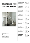
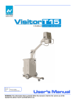
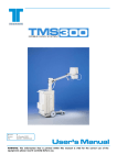
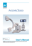
1
TECHNICAL DATA CARATTERISTICHE TECNICHE 1 M_30030B00R00.doc TECHNICAL MANUAL MANUALE TECNICO INSTALLATION & ACCEPTANCE INSTALLAZIONE E ACCETTAZIONE 2 M_30050B00R03.doc REPLACEMENTS SOSTITUZIONI 3 M_3009_B00R03.doc ADJUSTMENTS REGOLAZIONI 4 M_3011_B00R03.doc **** FAULTS FINDING RICERCA GUASTI 5 M_3013_B00R04.doc **** SERVICE INFORMATION INFORMAZIONI PER L’ASSISTENZA 6 M_30150B00R02.doc **** PARTS LIST LISTA PARTI DI RICAMBIO 7 M_30170E00R01.doc ELECTRICAL DRAWINGS 8 SCHEMI ELETTRICI M_3019_B00R03.doc PROGRAMMED MAINTENANCE MANUTENZIONE PROGRAMMATA 9 M_3021_B00R01.doc Manual Code: Revision Date: M_30000B00R04.doc 01 March 2004 ADDITIONAL INFORMATION INFORMAZIONI ADDIZIONALI M_30250B00R01.doc 10 Villa Sistemi Medicali VISITOR T15 – Technical data -1 TECHNICAL DATA CARATTERISTICHE TECNICHE [File: M_30030B00R00.doc] 1 Technical data -1 - VISITOR T15 Villa Sistemi Medicali (This page is intentionally left blank) (Pagina intenzionalmente bianca) [File: M_30030B00.doc] Villa Sistemi Medicali VISITOR T15 – Technical data -1 TABLE OF CONTENTS / SOMMARIO 1. Technical data / Caratteristiche tecniche ................................................................ ................................................................................................ ............................................................................. .............................................2 ............. 2 1.1. Electrical data / Dati elettrici .......................................................................................................................... 2 1.2. Functioning characteristics / Caratteristiche di funzionamento............................................................................ 3 1.3. Radiological characteristics / Caratteristiche radiologiche ................................................................................. 4 1.4. Mechanical characteristics / Caratteristiche meccaniche ................................................................................... 5 1.4.1. Unit volume sizes / Misure d’ingombro unità ................................................................................................ 6 1.5. Environmental data / Dati ambientali.............................................................................................................. 7 1.6. Components specifications / Caratteristiche componenti................................................................................... 7 1.6.1. Converter HF / Converter HF....................................................................................................................... 7 1.6.2. Tube-Housing Assembly / Complesso Tubo-Guaina...................................................................................... 8 1.6.3. Collimator / Collimatore............................................................................................................................ 12 1.7. Accessories and options / Accessori e opzioni ................................................................................................ 13 1.7.1. DAP meter (dose-area product meter) / DAP (misuratore del prodotto area-dose) ......................................... 13 2. Unit Labels / Etichettatura ................................................................ ................................................................................................ ............................................................................................... ...............................................................14 ............................... 14 3. ComplIance with directives and technical standards / Rispondenza alle direttive e norme tecniche ..............................15 .............................. 15 DOCUMENT STATUS ................................................................ ................................................................................................ ................................................................................................ ............................................................................... ...............................................I ............... I [File: M_30030B00.doc] Rev.0 - Page 1/16 Technical data -1 - VISITOR T15 1. Villa Sistemi Medicali TECHNICAL DATA / CARATTERISTICHE TECNICHE 1.1. Electrical data / Dati elettrici Description Voltage Data 115/230Vac ±10% monophase standard with the unit automatic adaptation to the mains (plug & play). 50/60Hz standard (See Note 1) Automatic <1Ω @115/230Vac 16A @230Vac Class I with applied parts type B Use conditions Continuos functioning with intermitting load The unit is not suitable for use in areas where there is a danger of inflammable mixtures of air or nitrous oxide. Frequency Absorbed current Line compensation Line resistance Standard mains plug Classification Values of absorbed current in the different use conditions: Descrizione Tensione Dati 115/230Vac ±10% monofase standard con predisposizione automatica dell’unità in funzione della linea d'alimentazione (plug & play) Frequenza 50/60Hz standard Corrente assorbita (Vedi Nota 1) Compensazione linea Automatica Resistenza di linea <1Ω @115/230Vac Spina di rete standard 16A @230Vac Classe di isolamento Classe I con parti applicate di tipo B Condizioni di impiego Funzionamento continuo con carico intermittente Apparecchio non adatto ad essere utilizzato in presenza di miscele infiammabili con aria o protossido di azoto Valori di corrente assorbita dall’unità nelle varie condizioni operative e nei due valori di alimentazione: Conditions Charger in working condition Stand By Stand By + Collimator Lamp Stand By + Charger in working condition Stand By + Collimator Lamp + Charger in working condition Preparation Preparation + Collimator Lamp X-Ray emission + Collimator Lamp Page 2/16 - Rev.0 [File: M_30030B00.doc] 115 Vac 50Hz 5,5 AMAX 0,87A 2,3A 5,1A 6,7A 230 Vac 50Hz 3,4AMAX 0,58A 1,5A 3,0A 3,8A 4,3A 5,5A 3APK 5,5A 7,3A 3APK Villa Sistemi Medicali VISITOR T15 – Technical data -1 1.2. Functioning characteristics / Caratteristiche di funzionamento Description User’s interface Settable languages Radiography control Safeties Data Keyboard with LCD alphanumeric display, 4 lines X 20 characters for all the operational parameters and messages of eventual faulty status. Service program for faults finding. Microprocessor management. English, Italian, French, German, Spanish, through configuration program. By push button with extendible cable. The last KV value used in manual mode or APR is shown. Upon ignition, the unit is in manual mode with default values. Filament current. Monobloc temperature. Overload. Max kV or H.V. fault Check and stored data capacity. Microcontroller auto test. Descrizione Dati Interfaccia utente Tastiera con display LCD alfanumerico 4 righe X 20 caratteri per tutti i parametri operativi e messaggi d’eventuali condizioni anomale. Programma di service per ricerca guasti. Gestione a microcontrollore. Lingue Italiano, Inglese, Francese, selezionabili Tedesco, Spagnolo, mediante programma di configurazione. Comando grafia A pulsante con cavetto estensibile. E’ proposto l'utilizzo dell'ultimo valore di kV utilizzati in tecnica manuale o APR. All’accensione l’unità si presenta in manuale con valori di default. Sicurezze Corrente di filamento. Temperatura monoblocco. Sovraccarico. Max kV o guasto in AT. Check e consistenza dati in memoria. Auto test microcontrollore. [File: M_30030B00R00.doc] Rev.0 - Pag. 3/19 Technical data -1 - VISITOR T15 Villa Sistemi Medicali 1.3. Radiological characteristics / Caratteristiche radiologiche Characteristic Working technique Performances 2 points technique with kV and mAs setting APR anatomical 24 exam memory (4 program programs each of 6 exams), available in the 5 different selectable languages. Exposure control Constant kV and mA during the whole exposure Power reduction Selection as L.P (50%) or H.P. (100%) Small focus in all the 0.8mm operating conditions (IEC 336) Generator power in 15kW @100kV DC current Inverter frequency Inverter Max. frequency in high voltage Max.ripple Rise time kV variation range mA variation range @115/230Vac mAs variation range @115/230Vac Range times @115/230Vac Use coefficient (duty cycle) kV 40 50 60 70 80 90 100 110 120 125 Page 4/16 - Rev.0 20kHz 40kHz <2% @100kV <2ms @100kV 40 ÷ 125kVp in step of 1kV 50 ÷ 200mA automatically associated to kV 0,2 ÷ 200mAs in 61 steps with increases of 12,5% 0,002 ÷ 2s in function of the set mAs 1:40 Caratteristica Tecnica di lavoro Tecnica anatomica APR Controllo esposizione Riduzione potenza Fuoco piccolo in tutte le condizioni operative (IEC 336) Potenza del generatore in corrente DC Frequenza inverter Max. frequenza inverter in alta tensione Ripple massimo Tempo di salita Range di variaz. kV Prestazioni A 2 punti con impostazione di kV e mAs Memorizzazione di 24 esami (4 cartelle da 6 esami ciascuna) disponibili nelle 5 diverse lingue selezionabili kV e mA costanti durante tutta l’esposizione E’ selezionabile tra L.P. (50%) o H.P. (100%) 0.8mm 15kW @100kV 20kHz 40kHz <2% @100kV <2ms @100kV 40 ÷ 125kVp in step da 1kV Range di variazione 50 ÷ 200mA associati in mA @115/230Vac automatico ai kV Range di variazione 0,2 ÷ 200mAs in 61 steps mAs @115/230Vac con incrementi del 12,5% Range tempi 0,002 ÷ 2s in funzione dei @115/230Vac mAs impostati Coefficiente d’utilizzo 1:40 (duty cycle) Valori mA @115/230Vac mAs>0,63 mAs<0,63 Mode1 Mode1/2 Mode1/2 (t<100ms) (t>100ms) 200mA 100mA 100mA 200mA 100mA 100mA 190mA 95mA 95mA 180mA 90mA 90mA 170mA 85mA 85mA 160mA 80mA 80mA 150mA 75mA 75mA 130mA 65mA 65mA 110mA 55mA 55mA 100mA 50mA 50mA [File: M_30030B00.doc] Valore di mAs in funzione dei kV @115/230Vac kV mAs 40 0.2 ÷ 200 41 ÷ 45 0.2 ÷ 180 46 ÷ 52 0.2 ÷ 160 53 ÷ 62 0.2 ÷ 140 63 ÷ 72 0.2 ÷ 125 73 ÷ 92 0.2 ÷ 100 93 ÷ 112 0.2 ÷ 80 113 ÷ 125 0.2 ÷ 71 Villa Sistemi Medicali VISITOR T15 – Technical data -1 1.4. Mechanical characteristics / Caratteristiche meccaniche Description Weight Max. width Length in transport position Descrizione Peso Larghezza massima Lunghezza in posizione di trasporto Max. height in transport Altezza max in posizione di position trasporto Max. height with the arm at Altezza max con braccio alla the max. extension massima estensione Control console height Altezza console di comando Focus-floor distance Distanza fuoco-pavimento Arm rotation around the Rotazione del braccio intorno vertical axis all’asse verticale Monobloc rotation around the Rotazione monoblocco arm axis intorno all’asse del braccio Monobloc rotation around its Rotazione del monoblocco axis intorno al suo asse Max. height of the unit front leg Cassette holder Movement Altezza massima gamba anteriore unità Portacassette Movimento Data 185kg (408Lb) approx. 700mm (27,56in) 1338mm (52,68in) 1458mm (57,40in) 2258mm (88,90in) 1000mm (39,37in) 456 ÷ 2018mm (17,95 ÷ 79,45in) n.a. ±180° 151° (+133° ÷ -18° from vertical axis / rispetto all’asse verticale) 105mm (4,13in) 5 cassettes format 35 x 43cm (12x15in) Manual. Two front double wheels. Two rear wheels. Parking brake controlled by the pedal. Tilting handle (obstacles over-passing). Manuale. Due ruote gemellate anteriori. Due ruote posteriore. Freno di stazionamento comandato da pedale. Maniglia per tilting (superamento ostacoli). Wheels diameter Diametro ruote Rear wheels: wheel Ø 250mm (9,84in), width 50mm (1,97in). Front wheels: double wheel Ø 80mm (3,15in), width 22mm (0,87in) Posteriori: Due ruote Ø 250mm(9,84in) larghezza 50mm (1,97in). Anteriori: Due ruote Ø 80mm (3,15in) larghezza 22mm (0,87in). [File: M_30030B00R00.doc] Rev.0 - Pag. 5/19 Technical data -1 - VISITOR T15 Villa Sistemi Medicali 1.4.1. Unit volume sizes / Misure d’ingombro unità Page 6/16 - Rev.0 [File: M_30030B00.doc] Villa Sistemi Medicali VISITOR T15 – Technical data -1 1.5. Environmental data / Dati ambientali Description Descrizione Temperature / Temperatura Relative humidity / Umidità relativa Pressure / Pressione Normal use Uso normale +10÷40 °C (+50÷104°F) 30÷75 % non condensing Transport and storage Trasporto e immagazzinamento -25÷+70°C (-13÷158°F) 10÷90% non condensing 700÷1060 hPa 500÷1060 hPa 1.6. Components specifications / Caratteristiche componenti 1.6.1. Converter HF / Converter HF Description Descrizione Data Inverter model Working frequency Max frequency in high voltage Power supply Dimensions Inverter modello Frequenza di lavoro Frequenza max in alta tensione IHF 2015 20kHz 40kHz Tensione di alimentazione Dimensioni Max. absorbed current Technology Safeties Corrente massima assorbita Tecnologia Sicurezze Generator power in constant DC current (IEC 601-1) Max. voltage to the tube Max. ripple at 100kVp Rise time at 100kVp Radiography current Potenza del generatore in corrente DC costante (IEC 601-1) Tensione massima al tubo Ripple massimo a 100 kVp Tempo di salita a 100 kVp Corrente in grafia 350Vdc max 190x130x140mm 7,48x5,12x5,51in 50A IGBT over current over voltage IGBT driver fault 15kW (150mA @ 100kV per 0.1s) [File: M_30030B00.doc] 125kVp <2% <2ms 200mA@50kV Rev.0 - Page 7/16 Technical data -1 - VISITOR T15 Villa Sistemi Medicali 1.6.2. TubeTube-Housing Housing Assembly / Complesso TuboTubo-Guaina X-Ray Tube / Tubo RX Description Type Anodic rated power (IEC 613, EN 60613) Nominal foci size (IEC 336, EN 60336) Speed of rotation Descizione Tipo Potenza anodica nominale (IEC 613, EN 60613) Dim. nominale fuochi (IEC 336, EN 60336) Velocità di rotazione Anodic diameter Anode material Anodic angle Tube material Min. inherent filtration (IEC 522) Diametro anodico Materiale anodo Angolo anodico Materiale tubo Filtrazione inerente minima (IEC 522) Capacità termica dell'anodo Massima dissipazione continua dell’anodo Massima velocità di raffreddamento anodo Alta tensione nominale Massima corrente di filamento Thermal anode capacity Max. continuous anode dissipation Max. anode cooling rate Nominal high-voltage Max. filament current Data X22 0.8/1.3 16kW/32kW 0.8mm – 1.3 mm 2850 rpm @ 50 Hz 3400 rpm @ 60 Hz 64mm (2,52in) Tungsten 15° Glass 0.7mmAl eq. 80kJ (107kHU) 300W 22kJ/min (29.5kHU/min) 130kV 5.4A Tube seasoning / Formazione tubo After a long idle period (3 months or more), it is necessary to proceed to the X-RAY TUBE SEASONING. The procedure and the tube seasoning modes are described in the Service Manual. Dopo ogni lungo periodo d’inattività (3 o più mesi) è necessario procedere alla FORMAZIONE DEL TUBO RX. La procedura e le modalità di formazione del tubo sono descritte nel Manuale di servizio. Dimensions / Dimensioni Page 8/16 - Rev.0 [File: M_30030B00.doc] Villa Sistemi Medicali VISITOR T15 – Technical data -1 Monobloc Description Monobloc model Weight Dimensions Descrizione Modello monoblocco Peso Dimensioni X-Ray tube model Anode Modello tubo RX Anodo External thermostat Monobloc thermal capacity Max continuous thermal dissipation of monobloc Total filtration Radiation leakage Termostato esterno Capacità termica monoblocco Max dissipazione termica continua monoblocco Filtrazione totale Radiazione di fuga Loading, heating and cooling curves H.V. Isolating transformer Distance focus-Collimator joint plane Curve di carico, riscaldamento, raffreddamento Isolamento trasformatore A.T. Distanza fuoco-piano montaggio collimatore Data MHF 2015 19kg 320x140x255mm 12,6x5,51x10,04in X22 0.8/1.3 Rotating (2850rpm a 50Hz) (3400rpm a 60Hz) 57° 600kJ (800kHU) 55W 2.7mm Al <1mGy/h according to IEC 6011-3 See the enclosed diagrams Oil bath 82.5mm (3,25in) Dimensions / Dimensioni [File: M_30030B00.doc] Rev.0 - Page 9/16 Technical data -1 - VISITOR T15 Villa Sistemi Medicali Single load curves / Curve di carico singolo 0.8 - 3~ - 3000min-1 Anodic current (mA) / Exposure Time (s) Corrente Anodica - Tube Current - Intensité Anodiqu (mA) 350 300 250 50 kV 60 kV 70 kV 80 kV 90 kV 100 kV 110 kV 120 kV 130 kV 200 150 100 50 0 0.01 0.1 1 10 Tempo di esposizione - Time - Temps (sec) Heating and cooling curves of anode / Curve di riscaldamento e raffreddamento dell’anodo Stored energy (kJ) / Time (min) Energia Accumulata - Stored Energy - Energie Emmagas (kJ) 80 800 W 500 W 70 300 W 60 200 W 50 100 W 40 30 20 10 0 0 5 10 Tempo - Time - Temps (min) Page 10/16 - Rev.0 [File: M_30030B00.doc] 15 Villa Sistemi Medicali VISITOR T15 – Technical data -1 Heating and cooling cooling curves of monobloc / Curve di riscaldamento e raffreddamento del monoblocco Stored energy (kJ) / Time (min) [File: M_30030B00.doc] Rev.0 - Page 11/16 Technical data -1 - VISITOR T15 Villa Sistemi Medicali 1.6.3. Collimator / Collimatore Description Type, brand and model Descrizione Tipo, marca e modello Collimator Collimazione Light source Sorgente luminosa Fuse Field covering Fusibile Copertura del campo Brightness intensity Contrast ratio Measure of focus-film distance Rotation Weight Sizes Intensità luminosa Rapporto di contrasto Misura distanza fuoco film Accessories Accessori Max protection against leaked radiation (EN60601-1-3 par.29.204.3) Indicator precision (EN60601-1-3 par.29.202.8) Max protezione contro le radiazioni disperse (EN60601-1-3 par.29.204.3) Precisione dell’indicatore (EN60601-1-3 par.29.202.8) Inherent filtration (EN60601-1-3 par.29.201.2/29.201.6) Brightness field precision (EN60601-1-3 par.29.202.9) Filtrazione inerente (EN60601-1-3 par.29.201.2/29.201.6) Precisione del campo luce (EN60601-1-3 par.29.202.9) Classification EN60601-1 par.5 Protection against electrical hazards Protection against direct and indirect contacts Classificazione EN60601-1 par.5 Protezione contro i pericoli elettrici Protezione contro i contatti diretti e indiretti Protection against water penetration Protezione contro la penetrazione di acqua Page 12/16 - Rev.0 Rotazione Peso Ingombri [File: M_30030B00.doc] Data Manual with internal light source (Ralco R221). Manuale con sorgente luminosa interna (Ralco R221). Square field, multilayers. Campo quadro, piani multipli. Halogen Lamp 12V 100W with temporized ignition at approx. 30s. Lampada alogena 12V 100W con accensione temporizzata circa 30s. 8A From 0x0cm (0x0in) to 43x43cm (16,93x16,93in )at 1m (39,37in) DFF 160lux at 1m DFF 4:1 Extensible measure ±115° 8,4kg (18,52Lb) 183x168x256mm (7,20x6,61x10,08in) Possibility of dosimeter insertion. Predisposizione per inserimento dosimetro. 125kV 4mA Corresponds to X-ray fields with tolerance lower than 2% of used FFD. Corrisponde ai campi raggi X con tolleranza minore del 2% del FFD usato. 2.0mmAl eq. Corresponds to the X-ray field with tolerance lower than the 2% of used FFD. Corrisponde ai campi raggi X con tolleranza minore del 2% del FFD usato. Class I Classe I Unit with applied part Type B. Apparecchio con parte applicata di Tipo B. Common protection (IPXO). Protezione comune (IPXO). Villa Sistemi Medicali VISITOR T15 – Technical data -1 1.7. Accessories and options / Accessori e opzioni Description Radiography button with extendible cable Descrizione Pulsante grafia con cavetto estensibile Connessione esterna per Potter External Potter Bucky connection Bucky Ionization chamber dosimeter, mod. Dosimetro a camera di ionizzazione, DIAMENTOR PX mod. DIAMENTOR PX T11020-00011 T11020-00011 Standard Standard Optional 1.7.1. DAP meter (dose(dose-area product meter) / DAP (misuratore del prodotto areaarea-dose) The DAPmeter is optional / Questo dispositivo è installato solo su richiesta. Description Type, brand and model Descrizione Tipo, marca e modello Measurement unit Resolution Dose-area product range Unità di misura Risoluzione Range prodotto dosearea Dose-area product summation Range sommatoria range prodotto dose-area Max. field size Massimo campo misura [File: M_30030B00.doc] Data Dosimeter with ionization chamber, PTW-Freiburg DIAMENTOR PX T11020-00011 cGycm2 0.1cGycm2 0.3 ÷ 15000 cGycm2 00000.0 ÷ 99999.9cGycm2 118mm x 118mm (4,65x4,65in) Rev.0 - Page 13/16 Technical data -1 - VISITOR T15 2. Villa Sistemi Medicali UNIT LABELS / ETICHETTATURA TECHNIX S.p.A. - Via E.Fermi 26 - 24050 Grassobbio - BG - ITALY Inverter IHF 2015 Mode Serial N. XXXXX Date mfg. XX-XX Power 15kW Supply 350 VDC DC/AC 20kHz Made in ITALY inverter label unit label collimator label monobloc external label Page 14/16 - Rev.0 [File: M_30030B00.doc] Villa Sistemi Medicali 3. VISITOR T15 – Technical data -1 COMPLIANCE WITH DIRECTIVES AND TECHNICAL STANDARDS / RISPONDENZA ALLE DIRETTIVE E NORME TECNICHE Reference MDD 93/42/EEC IEC 60601-1 IEC 60601-1-2 IEC 60601-1-3 IEC 60601-2-7 2nd edition IEC 60601-2-28 IEC 60336 Description Medical Devices Directive (CE mark) Medical devices safety Electromagnetic compatibility Protection against ionizing radiation High voltage generators Tube – housing groups X-ray tubes focus [File: M_30030B00.doc] Direttiva Dispositivi Medici (marcatura CE) Sicurezza dei dispositivi medici Compatibilità elettromagnetica Protezione contro le radiazioni ionizzanti Generatori d’alta tensione Complessi tubo - guaina Fuochi dei tubi radiogeni Rev.0 - Page 15/16 Technical data -1 - VISITOR T15 Villa Sistemi Medicali (This page is intentionally left blank) (Pagina intenzionalmente bianca) Page 16/16 - Rev.0 [File: M_30030B00.doc] Document Status VISITOR T15 – Technical data -1 DOCUMENT STATUS Rev. Date 0 27.08.03 Pages Modification description Document approval. 1 2 3 4 5 [File: M_30030B00R00.doc] Pag. I/I Villa Sistemi Medicali VISITOR T15 / VISITOR T30 – Additional information / Informazioni addizionali -10 ADDITIONAL INFORMATION INFORMAZIONI ADDIZIONALI [File: M_30250B00R01.doc] 10 Additional information / Informazioni addizionali -10 - VISITOR T15 / VISITOR T30 (This page is intentionally left blank) (Pagina intenzionalmente bianca) [File:M_3025_B00.doc] Villa Sistemi Medicali Villa Sistemi Medicali VISITOR T15 / VISITOR T30 – Additional information / Informazioni addizionali -10 TABLE OF CONTENTS / INDICE 1. TO OBTAIN ASSISTANCE / COSA FARE PER CHIEDERE ASSISTENZA ASSISTENZA ................................................................ ..................................................................... .....................................2 ..... 2 2. 3. TO CONTACT Villa Sistemi Medicali / COME CONTATTARCI...................................................................................................... 2 UNITS AND SPARE PARTS RETURN / RESTITUZIONE DISPOSITIVI O LORO PARTI .................................................... ....................................................3 .................... 3 3.1. 3.2. 3.3. MONOBLOC PACKING / IMBALLAGGIO DEL MONOBLOCCO ............................................................................................ 3 OTHER COMPONENTS PACKING / IMBALLAGGIO DI ALTRI COMPONENTI.......................................................................... 4 PACKING LABELS / ETICHETTE DA APPLICARE ALL’IMBALLO................................................................................................... 5 DOCUMENT STATUS / ST STATO ATO DEL DOCUMENTO ................................................................ ................................................................................................ ...................................................................... ......................................I ...... I [File:M_3025_B00.doc] Rev.1 - Page 1/6 Additional information / Informazioni addizionali -10 - VISITOR T15 / VISITOR T30 1. TO OBTAIN ASSISTANCE / COSA FARE PER CHIEDERE ASSISTENZA In case of problems, complaints, malfunction or faults of the unit, it is important to contact Villa Sistemi Medicali in order to arrange the correct remedial action. It is important to specify in detail the request reason, the unit type and the unit S/N whether Villa Sistemi Medicali is contacted by phone, by fax or by e-mail. 2. Villa Sistemi Medicali In caso di segnalazioni, reclami, malfunzionamenti o guasti dell’unità, è importante contattare al più presto Villa Sistemi Medicali per concordare le azioni correttive più opportune. Sia che Villa Sistemi Medicali venga contattata via telefono, via fax o via e-mail è importante specificare nel modo più dettagliato possibile il motivo della richiesta, insieme al tipo di unità e al numero di serie dell’unità stessa. TO CONTACT VILLA SISTEMI MEDICALI / COME CONTATTARCI VILLA SISTEMI MEDICALI Via delle Azalee, 3 20090 - Buccinasco - (MI) – Italia Tel: +39-02-48.859.1 Fax: +39-02-48.81.844 E-mail: [email protected] The manufacturer producer (according to European Directive 93/42/CEE) of VISITOR T15 / VISITOR T30 unit is: Il produttore (in accordo alla Direttiva Europea 93/42/CEE) dell’unità VISITOR T15 / VISITOR T30 è: Technix S.p.A. Via E. Fermi, 26 24050 Grassobbio, BG - ITALY Tel: +39 035 33 56 78 Fax: +39 035 33 56 75 Page 2/6 - Rev.1 [File:M_3025_B00.doc] Villa Sistemi Medicali 3. VISITOR T15 / VISITOR T30 – Additional information / Informazioni addizionali -10 UNITS AND SPARE PARTS RETURN / RESTITUZIONE DISPOSITIVI O LORO PARTI The return to Villa Sistemi Medicali units or spare parts for replacement under warranty or reparation, has to be previously agreed with Villa Sistemi Medicali, then every item has to be properly packed, in order to avoid any damages during the transportation. Villa Sistemi Medicali won’t be held liable for damages caused by unproper packing. A careful packing is required for fragile components, or containing fragile parts, in particular for the monobloc. 3.1. La restituzione in fabbrica di dispositivi o loro parti per sostituzione in garanzia o per riparazione devono essere preventivamente concordati con la Villa Sistemi Medicali e imballati in modo conveniente ad evitare qualsiasi danneggiamento dovuto al trasporto. Villa Sistemi Medicali non risponderà di danneggiamenti dovuti ad un imballaggio inadeguato. Un accurato imballaggio deve essere fatto a riguardo di componenti fragili o che contengono parti fragili, in modo particolare per il monoblocco. MONOBLOC PACKING / IMBALLAGGIO DEL MONOBLOCCO Protect the connectors board using anticollision materials (e.g. foam rubber). • Wrap the monobloc using double layers of polythene-bubble wrap. • Utilize, if possible, a wooden box with pallet; however, insert an anti-collision shim inside the container, in order to damp the monobloc weight. • Place the monobloc in vertical position in the middle of the box, as shown in the Fig.1, then fill the remaining space with anti-collision material (e.g. polystyrene), to keep it blocked. Close the box and stick labels of the type shown in the next page; should labels be not available, it’s possible to photocopy and cut out the same page. • Proteggere la scheda dei connettori con materiale antiurto (p.e.: gommapiuma). • Avvolgere il monoblocco con un paio di strati di foglio in polietilene-bolle. • Utilizzare se possibile una cassetta di legno con bancale; in ogni caso, di qualsiasi materiale sia il contenitore, sistemate sempre al suo interno uno spessore antiurto per ammortizzare il peso del monoblocco. • Al centro della cassetta adagiare il monoblocco in posizione verticale come indicato nella figura 1 e riempire lo spazio rimanente con materiale antiurto (p.e.: polistirolo) per mantenerlo bloccato. Chiudere la cassetta e applicarvi le etichette del tipo raffigurate alle pagine successive; se non sono a vostra disposizione potete utilizzare la pagina stessa facendone una fotocopia e ritagliarla. • [File:M_3025_B00.doc] Rev.1 - Page 3/6 Additional information / Informazioni addizionali -10 - VISITOR T15 / VISITOR T30 3.2. Villa Sistemi Medicali OTHER COMPONENTS PACKING / IMBALLAGGIO DI ALTRI COMPONENTI Other components have to be wrapped in polythene-bubble papers and placed in cardboard containers composed by several layers; fill the remaining space inside the box using anti-collision material. Furthermore, boards with electrical components have to be inserted in anti-static bags before their packing. Page 4/6 - Rev.1 Altri componenti devono essere avvolti in un foglio di polietilene-bolle e inscatolate in contenitori di cartone a più strati; riempire lo spazio rimanente all’interno della scatola con materiale antiurto. Le schede con componenti elettronici inoltre prima di essere messe in scatola dovranno essere racchiuse in un sacchetto antistatico. [File:M_3025_B00.doc] Villa Sistemi Medicali 3.3. VISITOR T15 / VISITOR T30 – Additional information / Informazioni addizionali -10 PACKING LABELS / ETICHETTE DA APPLICARE ALL’IMBALLO [File:M_3025_B00.doc] Rev.1 - Page 5/6 Additional information / Informazioni addizionali -10 - VISITOR T15 / VISITOR T30 (This page is intentionally left blank) (Pagina intenzionalmente bianca) Page 6/6 - Rev.1 [File:M_3025_B00.doc] Villa Sistemi Medicali Villa Sistemi Medicali VISITOR T15 / VISITOR T30 – Additional information / Informazioni addizionali -10 DOCUMENT STATUS / STATO DEL DOCUMENTO Rev. Date Page/s 0 01-09-03 - 1 17-06-03 - Description / Descrizione Document approval / Approvazione del documento. (Not available in double language / Non disponibile nella versione bilingue) Document general revision / Revisione generale documento 2 3 4 5 [File: M_30250B00R01.doc] Pag. I/I Villa Sistemi Medicali VISITOR T15 – Installation & Acceptance -2 INSTALLATION & ACCEPTANCE INSTALLAZIONE E ACCETTAZIONE [File: M_30050B00R03.doc] 2 Installation & Acceptance -2 - VISITOR T15 Villa Sistemi Medicali (This page is intentionally left blank) (Pagina intenzionalmente bianca) [File: M_30050B00.doc] Villa Sistemi Medicali VISITOR T15 – Installation & Acceptance -2 TABLE OF CONTENTS / SOMMARIO 1. How to proceed / Come procedere procedere ................................................................ ................................................................................................ .................................................................................... ....................................................2 .................... 2 2. Preliminary information / Informazioni preliminari ................................................................ ................................................................................................ ................................................................. ................................. 3 3. Unit unpacking / Disimballo................................ Disimballo ................................................................ ................................................................................................ .............................................................................................. ..............................................................4 .............................. 4 3.1. Unpacking procedure / Procedura per il disimballo .......................................................................................... 4 3.2. Packing and content description / Descrizione dell’imballo e del contenuto......................................................... 6 4. Sight check of the unit integrity / Verifica visiva integrità unità ................................................................ ................................................................................. .................................................7 ................. 7 5. Preliminary knowledges / Conoscenze preliminari ................................................................ ................................................................................................ ................................................................. ................................. 7 6. 7. Mechanical tests / Test funzionalità meccanica ................................................................ ................................................................................................ ..................................................................... .....................................8 ..... 8 ................................................................ ................................................................ ..................................................... .....................1 Unit supply / Alimentazione unità ................................ ................................ ................................ ..................... 12 7.1. Preliminary operations / Operazioni preliminari ............................................................................................. 12 7.2. Mains connection / Connessione alla rete ..................................................................................................... 12 8. Electrical tests (no irradiation) / Test funzionalità elettriche (non raggi) ................................................................ .................................................................... ....................................13 .... 13 8.1. Initialization - Start up – Ready / Accensione - Start up – Ready ....................................................................... 13 8.2. Collimator check / Verifica collimatore.......................................................................................................... 13 8.3. Data setting - preparation / Impostazione dati - Preparazione.......................................................................... 13 9. Accuracy test / Test di accuratezza accuratezza................................ atezza................................................................ ................................................................................................ .................................................................................... ....................................................14 .................... 14 9.1. Output data check / Controllo dati di uscita .................................................................................................. 14 9.2. X-ray irradiation field check / Controllo campo irradiato ................................................................................. 15 10. Unit configuration / Configurazione dell’unità ................................................................ ................................................................................................ ................................................................16 ................................ 16 10.1. Default configuration / Configurazione di default ........................................................................................... 16 10.2. Customer’s configuration / Personalizzazione della configurazione................................................................... 16 10.2.1. Configuration sheet / Scheda di configurazione .......................................................................................... 17 10.3. Configuration / Configurazione.................................................................................................................... 18 10.4. Date and time setting / Impostare data e ora................................................................................................. 18 11. Tube seasoning / Formazione del tubo ................................................................ ................................................................................................ ......................................................................... .........................................19 ......... 19 DOCUMENT STATUS / STATO DEL DOCUMENTO ................................................................ ................................................................................................ ...................................................................... ......................................I ...... I [File: M_30050B00.doc] Rev.3 - Page 1/20 Installation & Acceptance -2 - VISITOR T15 1. Villa Sistemi Medicali HOW TO PROCEED / COME PROCEDERE For the proper and safe installation of the unit, please follow, step by step, the INSTALLATION SHEET. Proceed to the next step only when the previous steps have been properly completed. Per una corretta e sicura installazione dell’unità consigliamo di seguire, passo dopo passo, la SCHEDA DI INSTALLAZIONE. Non eseguire il passo successivo se non si è sicuri di aver completato con cura il passo precedente. INSTALLATION SHEET / SCHEDA DI INSTALLAZIONE Rif. / Ref. Description / Descrizione Par. 2 Par. 3 Par. 4 Par. Par. 5 Par. 6 Par. 7 Par. 8 Par. 9 Par. 10 Preliminary knowledges and information Conoscenza informazioni preliminari Unpacking and content check Disimballo e verifica contenuto Sight check of the unit integrity * Verifica visiva integrità unità * Reading of the chapter “Service information” Conoscenza capitolo “informazioni per l’assistenza” Mechanical tests* Test funzionalità meccanica * Check of the supply mains/unit features compatibility Verifica compatibilità caratt. unità / rete Electrical tests (do not perform x-ray)* Test funzionalità elettriche (non raggi) * Accuracy test* Test di accuratezza * Unit configuration Configurazione unità Now the unit is ready for use Ora l’unità è pronta per l’utilizzo * Acceptance phase / fase di Accettazione Page 2/20 - Rev.3 [File: M_30050B00.doc] Result / Esito yes no yes no yes no yes no yes no yes no yes no yes no yes no ☺ !!EUREKA!! Villa Sistemi Medicali 2. VISITOR T15 – Installation & Acceptance -2 PRELIMINARY INFORMATION / INFORMAZIONI PRELIMINARI This unit has been manufactured and checked in factory by following production and testing methods which are in compliance with the most recent International Standards and with the European Directive for Medical Devices (93/42 EEC). During the testing, a Test Report including the following information: • • • Output data accuracy test (kV-mA-time) Light field X-ray field conformity test Electrical safety (PE resistance and leaked currents) Questa unità è stata costruita e controllata in fabbrica con metodi di produzione e di collaudo certificati dai più recenti standard internazionali e rispondenti alla direttiva europea dei dispositivi medici (93/42 CEE). In fase di collaudo un principalmente composto da: • • • Test Report Test di accuratezza dei dati di uscita (kVmA-time) Test di conformità campo luce - campo raggi Test di sicurezza elettrica (resistenza del PE e correnti disperse) To ensure that during the transport from the factory to the user the unit has not suffered any damage, some tests and functional checks are required. It is necessary to perform these tests during the installation. Per garantire che nel trasporto tra fabbrica e utilizzatore l’apparecchio non abbia subito danni e sia efficiente, sono richesti una serie di test e controlli funzionali. È necessario effettuare questi test durante l’installazione. To check the output data, it is necessary to use a non-invasive instrument for kV and x-ray time measurement. In case there is not this instrument, it is possible to check these values directly on the unit display (see the next pages). Per controllare i dati in uscita è necessario uno strumento non invasivo per la misura dei kV e del tempo RX. In assenza dello strumento è possibile controllarli direttamente sul display dell’apparecchio (vedi più avanti). Perform the operations described in this chapter if additional and specific acceptance tests are required (i.e. by hospital or Government). Nel caso fossero necessari controlli di accettazione specifici (dettati da regolamenti dell’ospedale o del Governo dell’utenza), prima di procedere eseguire quanto descritto in questo capitolo. DO NOT PERFORM RECKLESS OPERATIONS ELECTRICAL SHOCK DANGER Even if the mains plug is disconnected, a dangerous voltage can be present inside the unit if the capacitors battery is not completely discharged. discharged. NON ESEGUIRE MANOVRE AZZARDATE PERICOLO D’ELETTROCUZIONE Anche con spina d’alimentazione disinserita può essere presente una tensione pericolosa all’interno dell’apparecchiatura se la batteria di condensatori non è scarica. PERFORM THE DISCHARGE PROCEDURE Before performing any operation on Capacitors Battery, Power Unit, Inverter Power Circuits and Monobloc, it is necessary to discharge the capacitors battery. THE DISCHARGE PROCEDURE IS DESCRIBED IN THE CHAPTER “FAULTS FINDING”. ESEGUIRE LA PROCEDURA DI SCARICA Prima di eseguire qualsiasi operazione su Capacitors Battery, sul Power Unit, sui circuiti di potenza dell’Inverter e sul monoblocco è necessario scaricare la batteria di condensatori. LA PROCEDURA DI SCARICA È DESCRITTA NEL CAPITOLO “RICERCA GUASTI”. [File: M_30050B00.doc] Rev.3 - Page 3/20 Installation & Acceptance -2 - VISITOR T15 Villa Sistemi Medicali 3. UNIT UNPACKING / DISIMBALLO 3.1. Unpacking procedure / Procedura per il disimballo This procedure requires the intervention of two operators It is necessary to remove the locks and the screws of the assembling: • male hexagonal wrench d.5 mm • fixed wrench wrench d.17mm • crosshead screwdriver. In the packing there is a sliding side that is used to descend the unit from the pallet, however, it is possible to use the fork lift truck to remove it from the pallet. Il disimballo richiede l’intervento di due persone. Sono necessarie per rimuovere i fermi e le viti dell’imballo: • una chiave esagonale maschio d.5mm • una chiave fissa d. 17mm • un cacciavite Nell’imballo è presente una sponda con scivolo per far scendere l’apparecchiatura dal bancale, è possibile comunque utilizzare un carrello elevatore per rimuovere la stessa dal bancale. For a proper and safe unpacking of the unit, refer to the following procedure, complying with the current safety Standards. Before unpacking the unit, check the overturning indicator which is on the unit packing (Fig.1 Pos. 1). If the indicator is red, follow the instructions on the indicator and contact Villa Sistemi Medicali. Per un corretto e sicuro disimballo dell’unità fare riferimento alla proc procedura edura seguente attenendosi alle vigenti normative di sicurezza ed antifortunistica. Prima di procedere al disimballo dell’unità, verificare l’indicatore di rovesciamento posto sull’imballo dell’unità (Fig.1 Pos. 1). Se l’indicatore è rosso, seguire le istruzioni presenti sull’indicatore stesso ed avvertire Villa Sistemi Medicali. 1. Fig. 1 Ref. Fig. 1 Remove the screws pos. A by an hexagonal wrench ø5mm. Cut the plastic straps pos. B. Remove the packing covering and the polyethylene bag that protects the unit. Page 4/20 - Rev.3 Rif. Fig. 1 Con l’aiuto di una chiave esagonale ø5mm rimuovere le viti pos. A. Tagliare le regge di plastica pos. B. Rimuovere la copertura dell’imballo e il sacco di polietilene che protegge l’unità. [File: M_30050B00.doc] Villa Sistemi Medicali VISITOR T15 – Installation & Acceptance -2 2. Fig. 2 Ref. Fig. 2 Lower the ramp of the loading platform (pos. 1). Remove the two front fixing brackets (pos. 2) and the two rear fixing brackets (pos. 3), removing the nuts M10 with washer and grower that fix them to the loading platform. Remove the belt that lock the monobloc (pos. 4) and unlock the arm by placing it in horizontal position. Remove the monobloc support (pos 5) and place the arm in the lowered position again. Unlock the parking brakes (pos. 6) and slide the unit very carefully from the loading platform. Ref. Fig. 2 Abbassare lo scivolo del pianale (pos. 1). Rimuovere le due staffe di fissaggio anteriori (pos. 2) e le due staffe di fissaggio posteriori (pos. 3), togliendo i dadi M10 con rondella e grower che li fissano al pianale Rimuovere la cinghia che blocca il monoblocco (pos. 4) e sbloccare il braccio, portandolo in posizione orizzontale. Rimuovere il supporto monoblocco (pos 5) e riportare il braccio in posizione abbassata. Sbloccare i freni di stazionamento (pos. 6) e, prestando molta attenzione, far scivolare l’unità dal pianale. [File: M_30050B00.doc] Rev.3 - Page 5/20 Installation & Acceptance -2 - VISITOR T15 3.2. Villa Sistemi Medicali Packing and content description / Descrizione dell’imballo e del del contenuto Note: The packing content can change according to the chosen configuration; all the components that the packing can include are indicated here below. However, in order to know the real packing content, consult the document " PACKING LIST” enclosed to the received unit. Q.ty 1 Nota: il contenuto dell’imballo può variare a seconda della configurazione scelta, di seguito vengono indicati tutti i componenti che possono far parte dell’imballo. Ad ogni modo, per conoscere l’effettivo contenuto dell’imballo, consultare il documento “PACKING LIST” allegato ad ogni apparecchiatura. Description TX Code VISITOR T15 with equipment / con dotazione 63789/2 + 63663/1 Equipment / Dotazione: Q.ty 1 Description User’s manuals (on paper) / Manuali d’uso (su carta) 1 1 1 1 1 English language / Lingua inglese Italian language / Lingua italiana CD VISITOR T15 Service Manual + User’s Manuals in english and italian language. Manuale di servizio + Manuali d’uso in lingua inglese e italiana. Touch kit paints composed by: Kit vernice di ritocco composto da: M_30010E00 M_30010I00 63833/2 63750/2 1 White color paintpot RAL9002 1 Gray color paintpot RAL7038 72225 2 Touch-up brush 72222 Spare parts set composed by: Set di parti di ricambio composto da: 1 1 1 1 2 1 2 2 2 2 4 1 TX Code Halogen lamp 12V – 100W Fuse 5x20 T 250Ma / 250V Fuse 5x20 T 500Ma / 250V Fuse 5x20 T 1A / 250V Fuse 5x20 T 4A / 250V Fuse 5x20 T 10A / 250V Ceramic fuse 10x38 20A – Gg / 500V Extrafast fuse 63A – ETF / 660V Support for board locking EHCBS– 6 (h=10mm) Support for board locking EHCBS– 16 (h=25mm) Cables medium clip 150x3,6mm Connector kit for Potter made up of: Kit connettore Potter composto da: 1 1 10 Circular connector AMP 9 poles Shell for connector AMP Female AMP contact 72223 62918/2 11449 11361 11288 11289 11292 11150 12288 11456 11872 11867 11234 63659 12051 12052 12054 Optionals Devices / Dispositivi opzionali: 1 Page 6/20 - Rev.3 Dosimeter KIT (Diamentor PX mod. T11020) Kit Dosimetro (Diamentor PX mod. T11020) [File: M_30050B00.doc] 12192 Villa Sistemi Medicali 4. VISITOR T15 – Installation & Acceptance -2 SIGHT CHECK OF THE UNIT INTEGRITY / VERIFICA VISIVA INTEGRITÀ UNITÀ After the unit unpacking, check the integrity of the following parts: 1. 2. 3. 4. 5. 6. 7. 8. Labels Covers painting Keyboard Collimator and monobloc Handles Mains cable X-ray button and button cable Generator-monobloc-collimator connecting cable Any damage found on the unit must be communicated at the proper time to the carrier a and nd to the manufacturer. 5. Dopo che l’apparecchiatura è stata disimballata, controllare l’integrità dei seguenti particolari: Etichette di immatricolazione Verniciatura carterature Tastiera Collimatore e monoblocco Maniglie di movimentazione Cavo di alimentazione Cavo pulsante raggi e pulsante raggi Cavo collegamento generatore-monobloccocollimatore Ogni danno riscontrato all’apparecchiatura deve essere tempestivamente segnalato al trasportatore e al produttore. PRELIMINARY KNOWLEDGES / CONOSCENZE PRELIMINARI Before proceeding with the unit installation the technician must ccarefully arefully read the “information” in the chapter “Service information”. It includes useful information to properly perform the installation. Prima di procedere con l’installazione il tecnico deve leggere il capitolo “Informazioni per l’assistenza”, l’assistenza” in esso sono contenute informazioni indispensabili per eseguire una installazione corretta. [File: M_30050B00.doc] Rev.3 - Page 7/20 Installation & Acceptance -2 - VISITOR T15 6. Villa Sistemi Medicali MECHANICAL TESTS / TEST FUNZIONALITÀ MECCANICA 1. • • • Move the unit from the parking • position (see Fig. 4) Release the bracking handle (see Fig. • 3 pos.1) Rotate and pull the proper release • handgrip (see Fig. 5). Togliere l’unità dalla posizione di parcheggio (vedi Fig. 4). Sbloccare la maniglia di frenatura (vedi Fig. 3 pos.1). Ruotare e tirate l’apposita impugnatura di sgancio (vedi Fig. 5). Fig. 3 Fig. 4 Fig. 5 parking position posizione di parcheggio Page 8/20 - Rev.3 [File: M_30050B00.doc] Villa Sistemi Medicali 2. VISITOR T15 – Installation & Acceptance -2 Check the proper arm movement and Verificare la corretta escursione e balancing in every operative condition, as bilanciatura del braccio in tutte le shown in the Fig. 6. condizioni operative, come illustrato in Fig. 6. Fig. 6 3. Check the proper rotation and balancing of the monobloc-collimator group in respect of the transversal arm axis between –18° and +133° (see Fig. 7). Verificare la corretta rotazione e bilanciatura del gruppo monobloccocollimatore rispetto l’asse trasversale del braccio tra –18° e +133° (vedi Fig. 7). Fig. 7 [File: M_30050B00.doc] Rev.3 - Page 9/20 Installation & Acceptance -2 - VISITOR T15 4. Villa Sistemi Medicali Release the proper bracking handle (see Fig. 3 pos.2), check the correct monobloccollimator group rotation (±180°) in respect of its longitudinal axis (see Fig. 8) . Then check the proper goniometer indication. Sbloccando l’apposita maniglia di frenatura (vedi Fig. 3 pos.2), verificare la corretta rotazione del gruppo monoblocco-collimatore di ±180° rispetto l’asse longitudinale dello stesso (vedi Fig. 8). Verificare la corretta indicazione del goniometro. Fig. 8 Don’t move the group with a rotation over over ±180°. In order to place the group again at 0°, rotate it always in the direction opposed to the one used previously to not to damage the connecting cables. Page 10/20 - Rev.3 Non movimentare il gruppo con una rotazione maggiore di ±180°. 180°. Per posizionare di nuovo il grupp gruppo o a 0° ruotare lo stesso sempre nel verso opposto a quello utilizzato in precedenza in modo da non danneggiare i cavi di collegamento. [File: M_30050B00.doc] Villa Sistemi Medicali 5. VISITOR T15 – Installation & Acceptance -2 Check the correct collimator rotation (±130°) around the longitudinal axis of the monobloc-collimator group (see Fig. 9). Verificare la corretta rotazione del collimatore di ±130° attorno l’asse longitudinale del gruppo monobloccocollimatore (vedi Fig. 9). Fig. 9 6. Check the correct parking brake working (see Fig. 10). Place the pedal in the following positions and check the proper working: • pos. 1: brake OFF • pos. 2: brake ON Verificare il corretto funzionamento del freno di stazionamento (vedi Fig. 10). Posizionare il pedale nelle seguenti posizioni e verificarne l’effettivo funzionamento: • pos. 1: freno disattivato • pos. 2: freno attivato pos.1: brake off pos.1: freno disattivato pos.2: brake on pos.2: freno attivato Fig. 10 [File: M_30050B00.doc] Rev.3 - Page 11/20 Installation & Acceptance -2 - VISITOR T15 Villa Sistemi Medicali 7. UNIT SUPPLY / ALIMENTAZIONE UNITÀ 7.1. Preliminary operations / Operazioni preliminari VISITOR T15 has been designed to adapt automatically to the mains voltage and its performances don't change in function of the supply voltage (115V or 230V). Only the starting time of the rotating anode and so the preparation time are dependent on the voltage (0,8s @230Vac - 1,6s @115Vac). These times are selected automatically from the unit. Before connecting the unit to the mains, check the following conditions: 1. mains voltage 115V or 230V (±10%) monophase 2. mains frequency 50Hz or 60Hz 3. available power 3kW (16A max) 4. mains plug with earth connection L’unità è stata progettata per adeguarsi in modo automatico alla tensione di rete. Le prestazioni dell’unità non variano in funzione della tensione d’alimentazione (115V o 230V). Solo il tempo di lancio dell’anodo rotante, e quindi il tempo di preparazione, sono dipendenti dalla tensione (0.8s @230Vac 1.6s @115Vac). Questi tempi sono selezionati automaticamente dall’apparecchio. Prima di connettere l’unità alla rete accertarsi delle seguenti condizioni: 1. campo della tensione di rete 115V oppure 230V (±10%) monofase 2. frequenza di rete 50Hz o 60Hz 3. potenza disponibile 3kW (16A max) 4. presenza del conduttore di terra nella presa di alimentazione Before connecting the mains plug into the Prima di inserire la spina d’alimentazione nella socket, make sure that it is PROVIDED WITH presa accertarsi che questa SIA PROVVISTA THE GROUND CONNECTION. DEL COLLEGAMENTO DI TERRA. 7.2. Mains connection / Connessione alla rete At this point it is possible to connect the unit to the mains. A questo punto è possibile connettere l’unità alla rete. The presence of the mains voltage is indicated by the illumination of the yellow LED located near the ON button. If after connecting the plug to the mains the LED is off (not lit), check that the lever of the automatic switch on the unit side is UP (ON Position) La presenza di tensione d’alimentazione è indicata dall’accensione del led giallo posto a fianco del pulsante ON. Se con la spina inserita la spia fosse spenta controllare che la leva dell’interruttore automatico posto sul fianco dell’apparecchio sia alzata (posizione di ON). Page 12/20 - Rev.3 [File: M_30050B00.doc] Villa Sistemi Medicali 8. VISITOR T15 – Installation & Acceptance -2 ELECTRICAL TESTS (NO IRRADIATION) / TEST FUNZIONALITÀ ELETTRICHE (NON RAGGI) Don't perform any exposure in this phase. It In questa prima fase non comandare raggi, may be dangerous for the unit. può essere dann dannoso oso per l’unità. 8.1. Initialization - Start up – Ready / Accensione - Start up – Ready 1. Turn the unit ON by pressing the ON push-button, follow step by step the Start up sequence and check it is performing properly (refer to the chapter “Service information”). 2. At the end of the Start up the writing “READY” will be shown on the display. 8.2. Collimator check / Verifica collimatore 1. Open fully the collimator shutters. 2. By pressing the COLLIMATOR pushbutton on the keyboard, turn the collimator lamp ON, check the lamp lights up properly and check that it stays ON for about 30 seconds. 8.3. 1. Accendere l’unità, premendo il pulsante ON, seguire passo passo lo Start up e verificarne la corretta esecuzione (fare riferimento al capitolo “Informazioni per l’assistenza” per eventuali messaggi segnalati a display). 2. A Start up ultimato apparirà sul display la scritta “READY” (pronto). 1. Aprire completamente le lame del collimatore. 2. Dalla tastiera, premendo il pulsante COLLIMATOR, accendere la lampada del collimatore; controllare l’effettiva accensione della lampada e controllare che rimanga accesa per circa 30s. Data setting - preparation / Impostazione dati - Preparazione 1. Check the functioning of the kV and mAs increase/decrease push-buttons. 2. Perform a X-ray preparation (press only the first step of the handswitch for at least 3s) and check that the anode is in rotation. 3. When the handswitch is released, check that the anode is braked. 1. Verificare la funzionalità dei tasti incremento e decremento kV e mAs. 2. Eseguire una preparazione (premere solo il primo scatto del pulsante raggi per almeno 3s) e controllare che l’anodo sia in rotazione. 3. Al rilascio del pulsante controllare che l’anodo venga frenato. [File: M_30050B00.doc] Rev.3 - Page 13/20 Installation & Acceptance -2 - VISITOR T15 Villa Sistemi Medicali 9. ACCURACY TEST / TEST DI ACCURATEZZA 9.1. Output data check / Controllo dati di uscita WARNING Warning. Presence of xx-rays, use proper protections against radiation. ATTENZIONE Attività con presenza di raggi; proteggersi in modo adeguato. Place a non-invasive instrument for kV and xray time measurement under the x-ray beam according to that indicated in the instrument manual. Posizionare uno strumento non invasivo per la misura dei kV e del tempo sotto il fascio radiogeno in accordo con quanto indicato sul manuale dello strumento stesso. Perform the exposures listed in this table and compare the measured values with the allowed acceptance limits. Eseguire le radiografie indicate in tabella e confrontare i valori misurati con i limiti di accettazione proposti. Small focus kV mAs [ms] kV time [ms] Acceptance limit data output kV time [ms] 60 16 84 ............ ............ 57 - 63 80 – 88 80 16 94 ............ ............ 76 - 84 90 - 99 100 16 106 ............ ............ 95 -105 100 - 111 Set data output Theorical time Measured Measured value In case the instrument is not available: In assenza dello strumento: • it’s possible to check the X-ray time on the unit display directly; this is automatically displayed after every exposure; • • it is possible to check the kV (and anodic mA) from the SERVICE MODE, with the program TEST KV-mA as described in the chapter “Service information ”. • Page 14/20 - Rev.3 è possibile controllare il tempo direttamente sul display dell’unità; esso viene visualizzato automaticamente al termine di ogni radiografia; si possono verificare i kV ( e i mA anodici) dalla MODALITÁ SERVICE, con il programma TEST KV-mA come descritto nel capitolo “Informazioni per l’assistenza”. [File: M_30050B00.doc] Villa Sistemi Medicali X-ray irradiation field check / Controllo campo irradiato WARNING Warning. Presence of xx-rays, use the the proper protections against radiation. ATTENZIONE Attività con presenza di raggi; proteggersi in modo adeguato. Ref. Fig. 11 This test checks the correspondence between the collimator light and the irradiated field. Rif. Fig. 11 In questa prova si verificherà la corrispondenza tra luce collimatore e campo irradiato. 1. Collocare sotto il collimatore, ad una distanza di 1m (39,37in) dal fuoco, una cassetta radiografica 18x24cm (8x10in) con pellicola. 1. Place under the collimator, at a 1m (39,37in) distance from the focus, an x-ray cassette 18x24 (8x10in) with film. 39,37in 9.2. VISITOR T15 – Installation & Acceptance -2 8in 10 in Fig. 11 2. 3. 4. Press the push-button that switches ON the Premere il pulsante di accensione della centering lamp (operated from the lampada di centratura (si può agire sul collimator box or on the keyboard); the tasto del collimatore oppure sulla tastiera); la lampada resterà accesa per un periodo lamp will remain ON for approx. 30s di circa 30s. By using the handles placed on the Con le manopole poste sul fronte del collimator side, adjust the opening of the collimatore regolare l’apertura delle lamelle shutters so that only the cassette surface is in modo che sia illuminata solo tutta la superficie della cassetta. lit. Perform an exposure (i.e. 63kV/10mAs) and Eseguire un’esposizione (i.e. 63kV/10mAs) check that the film has been irradiated e controllare che la pellicola sia stata properly or is within the required tolerance. irraggiata in modo adeguato, o comunque entro la tolleranza richiesta. The X-ray data change in function of the cassette type and the used shields. As alternative to the cassette, it is possible to use a fluorescent, graduated and high persistence shield (field position analyzer). I dati radiologici variano in funzione del tipo di cassetta e di schermi utilizzati. In alternativa alla cassetta si può utilizzare uno schermo fluorescente ad alta persistenza e graduato (field position analyzer). [File: M_30050B00.doc] Rev.3 - Page 15/20 Installation & Acceptance -2 - VISITOR T15 Villa Sistemi Medicali 10. UNIT CONFIGURATION / CONFIGURAZIONE DELL’UNITÀ 10.1. Default configuration / Configurazione di default The unit has been programmed in the factory with the following configuration: L’apparecchio è stato programmato fabbrica nella seguente configurazione: in CONFIG Pag. Pag. Display Parameter Parametri Default Display 1/1 2/1 3/1 1/2 2/2 3/2 MAX. KV MAX.MAS APR mem. START KV START mAs LANGUAGE STARTER BRAKE LEVEL BUZZER DOSIMETER LOW-DOSE Max. kV Max. mAs Data change in APR Set kV at the switching on Set mAs at the switching on Language Massimi kV mAs massimi Cambio dei dati in APR kV impostati all’accensione mAs impostati all’accensione Lingua 125kV 200mAs disabled 63kV 4mAs English 125 200 OFF 63 4 ENG Anode braking Frenatura del’anodo enabled ON Audio signal level Livello del segnale acustico 3 (100%) 3 Dosimeter Low Power (50% reduction) Presenza del dosimetro Bassa Potenza (Riduzione 50%) not present enabled OFF ON 1/3 3/3 1/4 2/4 DATE Parameter/Parametri Default Display Calendar and time zone of Rome (GMT+1.00h) Date and time (DATE-TIME) 10.2. Customer’s configuration / Personalizzazione della configurazione The user has to be aware of the different working possibilities of the unit, thus to choose the most convenient and suitable configuration for its applications. Before proceeding with the configuration, it is necessary to fill out, together with the user, the CONFIGURATION SHEET (see the next page). Page 16/20 - Rev.3 È necessario che l’utilizzatore sia informato delle diverse possibilità di lavoro dell’apparecchio e che scelga la configurazione più conveniente per le sue applicazioni. Prima di passare alla configurazione vera e propria compilare assieme all’utilizzatore la SCHEDA DI CONFIGURAZIONE, proposta nella pagina seguente. [File: M_30050B00.doc] Villa Sistemi Medicali VISITOR T15 – Installation & Acceptance -2 10.2.1. Configuration sheet / Scheda di configurazione configurazione Unit: VISITOR T15 s/n°: Place of installation: Date of installation: Dept: Date of maintenance: Modello Unità: Luogo installazione: Data di installazione Reparto: Data manutenzione: Do you want to disable the anode braking when the preparation push-button is released or at the end of the x-ray emission? Definire il massimo valore di kV che si potrà impostare. (scegliere tra 40 e 125) Definire il massimo livello di mAs che si potrà impostare Definire la lingua con la quale verranno visualizzati i messaggi. (Scegliere tra Inglese, Spagnolo, Tedesco e Francese) Si vuole che sia possibile memorizzare i parametri di APR modificati dall’operatore? Definire il valore di kV con i quali l’apparecchio si predispone all’accensione. (scegliere tra 40 e il massimo valore di kV) Definire il valore di mAs con i quali l’apparecchio si predispone all’accensione. (scegliere tra 0,2 e il valore massimo di mAs) Si vuole disabilitare la frenatura dell’anodo ogni volta che si rilascia il pulsante di preparazione oppure al termine dell’emissione raggi? Determine the sound intensity level of the beeper on the unit. (choose between the levels 0=min. and 3=max.) Impostare il livello del segnale acustico del buzzer sull’apparecchio. (choose between the levels 0=min. and 3=max.) Determine the max.value of the settable kV (choose between 40 and 125) Determine the max.value of the settable mAs. Determine the language with which the messages will be shown on the display. (choose among English, French, German and Spanish) Do you want to be able to store the APR parameters modified by the operator? Determine the kV values with which the unit sets at the switching-ON (choose between 40 and the max. kV value) Determine the mAs values with which the unit sets at the switching-ON (choose between 0,2 and the max. mAs value) Is there the DAPmeter on the unit? (accessory supplied on request) Would you prefer that, when it is switched on, the unit sets in LOW POWER? User’s signature: signature: Firma dell’Utente: Sull’unità è presente il dosimetro integrato? (accessorio fornito su richiesta) Si vuole che all’accensione l’unità si predisponga in LOW POWER? ..……….kV ……….mAs ………………. yes no ………….kV ……….mAs yes no 3 100% 1 50% 2 75% 0 25% yes no yes no Technician’s signature: Firma del Tecnico: [File: M_30050B00.doc] Rev.3 - Page 17/20 Installation & Acceptance -2 - VISITOR T15 Villa Sistemi Medicali 10.3. Configuration / Configurazione Ora è possibile configurare l’unità con i dati riportati nella SCHEDA DI CONFIGURAZIONE. Attivare, dalla MODALITÁ SERVICE, la funzione CONFIG (vedi capitolo “Informazioni per l’assistenza”) e modificare i parametri. Please note that, with the service technician’s Tenere presente che con l’intervento del intervention, it will be always possible to modify tecnico di assistenza sarà sempre possibile modificare i parametri di configurazione. the configuration parameters. Now it is possible to set the unit with the data indicated in the CONFIGURATION SHEET. From SERVICE MODE activate the CONFIG function (see the chapter “Service information”) and change the parameters. 10.4. Date and time setting / Impostare data e ora Set date and time by following the DATE-TIME Regolare la data e l’ora con la procedura procedure (please refer to SEVICE MODE in DATE-TIME (vedi MODALITÁ SERVICE, nel the chapter “Service information”). capitolo “Informazioni per l’assistenza”). With the service personnel intervention, it will be always possible to change the configuration parameters. Page 18/20 - Rev.3 Con l’intervento del personale di Service, sarà sempre possibile modificare i parametri di configurazione. [File: M_30050B00.doc] Villa Sistemi Medicali VISITOR T15 – Installation & Acceptance -2 11. TUBE SEASONING / FORMAZIONE DEL TUBO If during the Start up phase, the display shows the message “TUBE SEASONING” is because the unit hasn't been used for more than 3 months. Therefore, it is necessary to perform the x-ray tube seasoning by following the TUBE SEASONING program (refer to SERVICE MODES, chapt. “Service information”). Se nella fase di Start up il display visualizza il messaggio “TUBE SEASONING” è perché l’apparecchio è rimasto inutilizzato per più di 3 mesi. In questo caso è necessario eseguire la formazione del tubo radiogeno con il programma TUBE SEASONING (vedi MODALITÁ SERVICE, capitolo “Informazioni per l’assistenza”). WARNING Warning. Presence of xx-rays, use proper proper protections against radiation. ATTENZIONE Attività con presenza di raggi; proteggersi in modo adeguato. Prepare the x-ray tube for the emission by performing the heating (Warm-up) and the kV rise (kV step-up) kVup. Perform these procedures by following the TUBE SEASONING program (refer to SERVICE MODES, chapt. “Service information”). Preparare il tubo radiogeno all’emissione eseguendo il riscaldamento (Warm-up) Warm e la salita dei kV (kV step-up) kVup . Eseguire queste procedure con il programma TUBE SEASONING (vedi MODALITÁ SERVICE, capitolo “Informazioni per l’assistenza”). After the seasoning DON'T perform any exposure. Let the monobloc cool for 8 minutes. Terminata la formazione non eseguire nuove esposizioni. LLasciare asciare prima raffreddare il monoblocco per 8 minuti. [File: M_30050B00.doc] Rev.3 - Page 19/20 Installation & Acceptance -2 - VISITOR T15 Villa Sistemi Medicali (This page is intentionally left blank) (Pagina intenzionalmente bianca) Page 20/20 - Rev.3 [File: M_30050B00.doc] Document Status / Stato del documento VISITOR T15 – Installation & Acceptance -2 DOCUMENT STATUS / STATO DEL DOCUMENTO Rev. Date Data 0 01-09-03 1 22-01-02 Pages Pagine Modification description Descrizione della modifica Document approval / Approvazione del documento (Not available in double language / Non disponibile nella versione bilingue) 6 16,17 Added description of the kit for potter Modified unit configuration Aggiunta descrizione del kit per potter Modificata configurazione unità (Not available in double language / Non disponibile nella versione bilingue) 2 17-06-03 Introduction of the new mechanical structrure of the unit. All / Tutte Introduzione nuova struttura meccanica dell’apparecchiatura. (Not available in double language / Non disponibile nella versione bilingue) 3 01-12-03 All / Tutte General revision of the chapter Revisione generale del capitolo 4 5 [File: M_30050B00R03.doc] Pag. I/I Villa Sistemi Medicali VISITOR T15 – Replacement / Sostituzioni -3 REPLACEMENTS SOSTITUZIONI [File: M_3009_B00R03.doc] 3 Replacement / Sostituzioni -3 - VISITOR T15 Villa Sistemi Medicali (This page is intentionally left blank) [File: M_3009_B00.doc] Villa Sistemi Medicali VISITOR T15 – Replacement / Sostituzioni -3 TABLE OF CONTENTS / SOMMARIO 1. Procedures description / Descrizione delle procedure ................................................................ ............................................................................................ ............................................................2 ............................ 2 1.1. Electrical parts replacement / Sostituzioni parti elettriche ................................................................................... 2 1.1.1. Control panel replacement / Sostituzione della tastiera.................................................................................. 3 1.1.2. Replacement of the firmware version / Sostituzione versione firmware ............................................................ 4 1.1.3. Replacement of the inverter protection fuse / Sostituzione del fusibile di protezione dell’inverter....................... 6 1.2. Mechanical parts replacement / Sostituzioni parti meccaniche ........................................................................... 8 1.2.1. Collimator lamp replacement / Sostituzione della lampada............................................................................ 8 1.2.2. Monobloc replacement / Sostituzione del monoblocco ................................................................................ 11 1.2.3. Collimator replacement / Sostituzione collimatore ....................................................................................... 14 1.2.4. Replacement of the monobloc handle......................................................................................................... 16 DOCUMENT STATUS / STATO DEL DOCUMENTO ................................................................ ................................................................................................ ...................................................................... ......................................I ...... I [File: M_3009_B00.doc] Rev.3 - Page 1/16 Replacement / Sostituzioni -3 - VISITOR T15 1. Villa Sistemi Medicali PROCEDURES DESCRIPTION / DESCRIZIONE DELLE PROCEDURE 1.1. Electrical parts replacement / Sostituzioni parti elettriche Should a fault or a malfunctioning be detected, it is advisable to replace the boards (and not to repair them). The boards provided will be already tested and adjusted. In case of any adjustment, please refer to the chapter “Adjustments”. In caso di guasto o malfunzionamento si consiglia di sostituire le schede anziché ripararle. Le schede nuove verranno fornite già collaudate e tarate. In caso di regolazioni fare riferimento al capitolo “Regolazioni”. All the adjustments of the electrical parts are performed without the frontal cover of the unit. Proceed in the following way: • Disconnect the unit from the mains. • Remove the cover. • Remove the ground cable fixed in the lower part of the cover. Tutte le sostituzioni delle parti elettriche devono essere eseguite senza il carter frontale dell’unità. Procedere nel seguente modo: • Sconnettere l’unità dalla rete. • Togliere il carter. • Togliere il cavo di terra fissato nella parte bassa del carter. DO NOT PERFORM HAZARDOUS OPERATIONS, ELECTICAL SHOCK DANGER When the mains plug is disconnected a dangerous voltage can still be present inside the unit if the capacitors battery is not completely discharged. NON ESEGUIRE MANOVRE AZZARDATE, PERICOLO D’ELETTROCUZIONE Anche con la spina d’alimentazione disinserita può essere presente una tensione pericolosa all’interno dell’apparecchiatura nel caso in cui la batteria di condensatori non è scarica. PERFORM THE DISCHARGE PROCEDURE Before performing any operation on the Capacitors Battery, on the Power Unit, on the Inverter Power Circuits and on the Monobloc it is necessary to discharge the capacitors battery. ESEGUIRE LA PROCEDURA DI SCARICA Prima di eseguire qualsiasi operazione su Capacitors Battery, sul Power Unit, sui Circuiti di Potenza dell’Inverter e sul Monoblocco è necessario scaricare la batteria di condensatori. The discharge procedure is described in the Chapter 5 “Faults finding”. La procedura di scarica è descritta nel Capitolo 5 “Ricerca Guasti”. Page 2/16 - Rev.3 [File: M_3009_B00.doc] Villa Sistemi Medicali VISITOR T15 – Replacement / Sostituzioni -3 1.1.1. Control panel replacement / Sostituzione della tastiera • • Disconnect the unit from the mains. Remove the frontal cover of the unit. • • Rif. Fig. 1 Ref. Fig. 1 • • • • • Sconnettere l’unità dalla rete. Togliere il carter frontale dell’unità. Detach the 6 poles flat-cable (pos.3) and the 26 poles flat-cable (pos.4) Remove the eight stop nuts ø 3 with flat washer (pos. 2) that fix the control panel from the unit inside. Detach the ground cable (pos.5) fixed with nut M3 and plain and grower washers. Reassemble the control panel by repeating the operations described here above in reverse. Perform some functional tests. • • • • • Staccare il flat-cable 6 poli (pos.3) e il flat-cable 26 poli (pos.4) Togliere gli otto dadi autobloccanti ø3 con rondella piana (pos. 2) che fissano la tastiera dall’interno dell’unità. Staccare il cavo di terra (pos.5) fissato con dado M3 e rondelle piane e grower Rimontare la tastiera ripetendo le operazioni sopra descritte in senso inverso. Eseguire prove funzionali. Fig. 1 [File: M_3009_B00.doc] Rev.3 - Page 3/16 Replacement / Sostituzioni -3 - VISITOR T15 Villa Sistemi Medicali 1.1.2. Replacement of the firmware version / Sostituzione versione versione firmware The replacement of the unit firmware is performed only in case of software version updating. In this case, it is necessary to replace the component IC22 (“MPU”) present on the board “B2 Processor Control Board”. La sostituzione del firmware dell’unità deve essere eseguita solo in caso di aggiornamento della versione software. In questo caso, è necessario sostituire il componente IC22 (“MPU”) presente sulla scheda “B2 Processor Control Board”. Follow the instructions below: Procedere nel seguente modo: • • • • Disconnect the unit from the mains. Remove the frontal cover of the unit. Identify the “B2” board that is in front of the user. Identify the component IC22 (“MPU”) in the left corner in the lower part of “B2” board (See following picture). • • • • Sconnettere l’unità dalla rete. Togliere il carter frontale dell’unità. Identificare la scheda “B2”, che si trova di fronte all’utilizzatore. Identificare il componente IC22 (“MPU”) nell’angolo sinistro in basso della scheda “B2” (Vedi figura seguente:). Point “A” Point “B” IC22 Board “B2” • Page 4/16 - Rev.3 SENSITIVE MATERIAL TO ELECTROSTATIC SHOCKS HANDLE WITH CARE MATERIALE SENSIBILE A SCARICHE ELETTROSTATICHE MANEGGIARE CON CURA WARNING: Necessary tools: PLCC EXTRACTOR (in order to pull out the MPU). ATTENZIONE: Per la rimozione dell’MPU è necessario il “PLCC EXTRACTOR”. Insert the proper tool in the points “A” and “B” and remove with care the MPU. • Inserire l’apposito attrezzo nei punti “A” e “B” e rimuovere con molta cautela l’MPU. [File: M_3009_B00.doc] Villa Sistemi Medicali • VISITOR T15 – Replacement / Sostituzioni -3 Insert the new MPU, paying attention to its polarization. (pin 1 downwards) WARNING: Because of the min. distance between the MPU pins, if this is not inserted with care, it is possible that some short circuits between the pins occur. • Inserire il nuovo MPU prestando molta attenzione alla polarizzazione dello stesso. ( pin 1 rivolto verso il basso) ATTENZIONE: A causa della minima distanza tra i pin dell’MPU, se questo non viene iinserito nserito con particolare attenzione, è possibile che verifichino corto circuiti tra i pin stessi. Pin 1 • • Check that the MPU is inserted completely and properly. Turn the unit ON and check that the ignition procedure occurs properly (refer to Chapt. “Service Information – 6” paragraph ‘Ignition and StartUp’) and that on the display the unit name and the version are the same of those present on the MPU label. WARNING: By replacing the component IC22 the information about the configuration and thecalibrations about the unit are not lost. • Reassemble the frontal cover of the unit. • • Verificare che l’MPU sia inserito completamente e in modo corretto. Accendere l’unità e verificare che la procedura di accensione si verifichi in modo corretto (vedi capitolo “Informazioni per l’Assistenza – 6” paragrafo ‘Accensione e StartUp’) e che sul display appaiano nome unità e versione uguali a quelli presenti sull’etichetta dell’MPU. ATTENZIONE: Con la sostituzione del componente IC22 non vengono perse le informazionirelative alla configurazione configurazione e alle tarature relative all’unità. • Rimontare dell’unità. [File: M_3009_B00.doc] il carter frontale Rev.3 - Page 5/16 Replacement / Sostituzioni -3 - VISITOR T15 Villa Sistemi Medicali 1.1.3. Replacement of the inverter protection fuse / Sostituzione del fusibile di protezione dell’inverter • • • The inverter protection fuses (B6-F1,F2 63A 660V) are placed on the “B6 Chooper” board, and they are accessible only by removing the unit cover and the plexiglass protection of the capacitors batteries. Disconnect the unit from the mains. Remove the frontal cover of the unit. • • • I fusibili di protezione dell’inverter (B6F1,F2 - 63A 660V) sono posizionati sulla scheda “B6 Chooper”, e sono accessibili solo togliendo il carter dell’unità e la protezione in plexiglass delle batterie di condensatori. Sconnettere l’unità dalla rete. Togliere il carter frontale dell’unità. DO NOT PERFORM HAZARDOUS OPERATIONS, ELECTICAL SHOCK DANGER Also if the mains plug is disconnected a dangerous voltage can be present inside the unit, if the capacitors battery is not completely discharged. NON ESEGUIRE MANOVRE AZZARDATE, PERICOLO D’ELETTROCUZIONE Anche con la spina d’alimentazione disinserita può essere presente una tensione pericolosa all’interno dell’apparecchiatura nel caso in cui la batteria di condensatori non è scarica. PERFORM THE DISCHARGE PROCEDURE Before performing any operation on the Capacitors Battery, on the Power Unit, on the Inverter Power Circuits and on the Monobloc it is necessary to discharge the capacitors battery. ESEGUIRE LA PROCEDURA DI SCARICA Prima di eseguire qualsiasi operazione su Capacitors Battery, sul Power Unit, sui Circuiti di Potenza dell’Inverter e sul Monoblocco è necessario scaricare la batteria di condensatori. The discharge procedure is described in the Chapter 5 “Faults finding”. La procedura di scarica è descritta nel Capitolo 5 “Ricerca Guasti”. Page 6/16 - Rev.3 [File: M_3009_B00.doc] Villa Sistemi Medicali VISITOR T15 – Replacement / Sostituzioni -3 Ref. Fig. 2 • Make sure that the batteries are completely discharged, on the contrary perform the batteries discharge procedure described in chapt. “Fault finding – 5”. • Remove the three fixing screws M3x8 with plain and grower washers that fix the plexiglass protection of the capacitors batteries (pos.2). • Remove the two screws TCEI M4x12 with plain and grower fixing washers of the battery (pos. 3) and, by pulling, take the battery out. • The inverter protection fuse becomes visible on the left battery. Rif. Fig. 2 • Assicurarsi che le batterie siano completamente scariche, in caso contrario eseguire la procedura di scarica delle batterie descritta nel capitolo “Ricerca guasti – 5”. • Togliere le tre viti di fissaggio M3x8 con rondella piana e grower che fiassano la protezione in plexiglass delle batterie di condensatori (pos.2). • Togliere le due viti TCEI M4x12 con rondella piana e grower di fissaggio della batteria (pos. 3) e, tirando verso di sé, estrarre la batteria. • Il fusibile di protezione dell’inverter diventa visibile sulla batteria di sinistra. Fig. 2 Ref. Fig. 3 • The fuses F1-F2 (pos. 1) are fixed to the board through two screws M5x12 with plain and grower washers. • Replace the fuses F1-F2 with those in the unit. • Repeat the operations described here above in reverse. • Perform some functional tests. Rif. Fig. 3 • I fusibili F1-F2 (pos. 1) sono fissati alla scheda tramite due viti M5x12 con rondelle piane e grower. • Sostituire i fusibili F1-F2 con quelli in dotazione alla macchina. • Ripetere le operazioni sopra descritte in senso inverso. • Eseguire prove funzionali. 1 Fig. 3 [File: M_3009_B00.doc] Rev.3 - Page 7/16 Replacement / Sostituzioni -3 - VISITOR T15 Villa Sistemi Medicali 1.2. Mechanical parts replacement / Sostituzioni parti meccaniche 1.2.1. Collimator lamp replacement / Sostituzione della lampada WARNING: before proceeding make sure of the lamp bracket, lamp and socket cooling. Danger of fingers burning!!. ATTENZIONE: prima di toccare il carterino di protezione, la lampada e lo zoccolo porta lampada con le mani assicurarsi che siano freddi. Po Possono ssono provocare ustioni. 1. • Disconnect the mains. • Block the unit brakes. • Park the arm in the lowered position and activate the safety brake. • Completely close the shutters (The arrows on the knobs should point to the bottom). • The collimator appears as follows: 1. • Sconnettere l’unità dalla rete. • Bloccare i freni dell’unità. • Bloccare il braccio nella posizione inferiore e attivare il blocco di sicurezza. • Chiudere completamente le lamelle (la freccia delle manopole punterà verso il basso. • Il collimatore si presenta come segue: 2. • Remove the knobs (2 hexagonal, ø2mm). 2. • Rimuovere le manopole (2 viti con impronta esagonale incassata ∅2mm). Page 8/16 - Rev.3 [File: M_3009_B00.doc] Villa Sistemi Medicali VISITOR T15 – Replacement / Sostituzioni -3 3. • Remove the front cover and frame (2 screws). Be aware of the lamp button cables if it is necessary to remove the button. 3. • Rimuovere lamierino e cornice anteriore (2 viti) facendo attenzione ai cablaggi del pulsante lampada, nel caso rimuovere il pulsante. 4. • Remove the 2 screws and the spacers of the lamp protection cover. 4. • Rimuovere le 2 viti e i distanziali del carterino protezione lampada. [File: M_3009_B00.doc] Rev.3 - Page 9/16 Replacement / Sostituzioni -3 - VISITOR T15 Villa Sistemi Medicali 5. • Carefully remove the faulty lamp. • Replace the lamp with a new one type: PHILIPS PROJECTION LAMP Type 7023 FCR A1/215 12V 100W GY6.35 cod. 3222 617 51621 cod. 7222 613 32021 or equivalent 5. • Con cautela rimuovere la lampada guasta. • Sostituire la lampada con una di tipo: PHILIPS PROJECTION LAMP Type 7023 FCR A1/215 12V 100W GY6.35 cod. 3222 617 51621 cod. 7222 613 32021 od equivalente EVEN IF COLD, NEVER TOUCH THE LAMP WITH UNPROTECTED HANDS!! LA LAMPADA, ANCHE SE FREDDA, NON VA MAI TOCCATA CON LE MANI NUDE 6. • Make sure that the lamp pins are completely inserted in the lamp-holder. 6. Assicurarsi che i pin della lampada siano completamente inseriti nello zoccolo portalampada 7. • Follow the foregoing steps from the bottom to re-mount the collimator assembly. 7. Seguire le istruzioni precedenti a ritroso e rimontare il collimatore. 8. • Before remounting the handles close both shutters and adjust the handle indicators. 8. Prima di rimontare le manopole verificare che siano chiuse entrambe le lamelle. Regolare la manopola indicatrice sullo zero. Page 10/16 - Rev.3 [File: M_3009_B00.doc] Villa Sistemi Medicali VISITOR T15 – Replacement / Sostituzioni -3 1.2.2. Monobloc replacement / Sostituzione del monoblocco This procedure can cause severe and serious damages to unit and/or operators. Act VERY CAREFULLY while performing any operation. 1. How to arrange arrange the unit for the replacement. • Disconnect the unit from the mains. • Block the unit brakes. • Park the arm in horizontal position. • Properly stretch a stout belt or a rope (resisting to 100kgf/1000N at least) between arm and front leg. • Make sure that the rope cannot slide towards the arm pivot. To perform this operation, tightly bind the rope between the blocking handle for the rotation and the monobloc stirrup. Furthermore, check that the rope is well stretched. IMPORTANT: When the monobloc is removed from its support, a force at the arm extremity directed to the top, will be present (of approx. 40kgf/400N). Questa procedura può causare gravissime conseguenze all’unità o alle persone. Prestare la massima attenzione ad ogni operazione eseguita. 1. Preparazione dell’unità alla sostituzione. • Sconnettere l’unità dalla rete. • Bloccare i freni dell’unità. • Posizionare il braccio nella posizione orizzontale. • Legare in modo adeguato una cinghia o una corda resistente ad una trazione di almeno 100kgf/1000N tra il braccio e la gamba anteriore. • Assicurarsi che la corda non possa scivolare verso il perno del braccio, quindi legarla strettamente tra la maniglia di blocco rotazione e la staffa del monoblocco. Assicurarsi, inoltre, che la corda sia ben tesa. IMPORTANTE: Quando il monoblocco sarà rimosso sarà presente, all’estremità del braccio, una forza di circa 40kgf/400N verso l’alto. [File: M_3009_B00.doc] Rev.3 - Page 11/16 Replacement / Sostituzioni -3 - VISITOR T15 Villa Sistemi Medicali 3. How to remove the monobloc. • Loosen the 4 lateral screws and remove the monobloc cover support. • Disconnect the supply and signal cables from the monobloc: the connection is performed by tearing clamps. No tool is required, except for the ground conductor. 3. Rimuovere il monoblocco. • Rimuovere il supporto del carter del monoblocco svitando le 4 viti laterali. • Scollegare dal monoblocco i cavi di alimentazione e di controllo: il collegamento è effettuato tramite morsetti a strappo, non è necessario utilizzare alcun utensile se non per il conduttore di terra. ATTENTION: the following step is the most dangerous. The rope will be subjected to a sudden tension of several kgf (>60kgf); if rope and hitches are not properly stout the arm could arise suddenly, causing really severe damages for the operators around and the unit. Before removing the monobloc, it is advisable to carefully stretch the rope as much as possible, so that it will be subjected to fewer stresses. ATTENZIONE: il successivo punto è il più pericoloso. La corda subirà una tensione improvvisa di parecchi kgf (>60kgf); se la corda e i nodi non sono adeguatamente robusti il braccio potrebbe alzarsi di colpo con gravissimi danni per le persone circostanti e per l’unità. l’unità. È consigliabile tendere bene la corda prima di rimuovere il monoblocco, questa è la condizione in cui la corda subirà meno sollecitazioni. • Loosen the 4 nuts with plain and Grower washers which fix the monobloc to the support. This way, the monobloc is completely free and, acting very carefully, can be removed. ATTENTION: For any reason, DO NOT REMOVE or UNUNSTRETCH the rope. In this status the unit becomes very dangerous, therefore, operate such as to leave the unit in this condition for as short a time as possible. None, except the technician who wi willll rere-mount the monobloc, must approach the unit. Do not leave the unit unguarded. Page 12/16 - Rev.3 • Svitare i 4 dati con rondella piana e Grower che fissano il monoblocco al supporto, a questo punto il monoblocco è completamente libero e, con cautela, può essere rimosso. ATTENZIONE: A questo punto non rimuovere o slegare per nessun motivo la corda. In questa condizione l’unità è potenzialmente molto pericolosa quindi fare in modo che l’unità stia in questa condizione il meno tempo possibile. Nessuno, eccetto il tecnico che rimonterà il monoblocco, deve avvicinarsi all’unità. Non lasciare l’apparecchio incustodito. [File: M_3009_B00.doc] Villa Sistemi Medicali VISITOR T15 – Replacement / Sostituzioni -3 4. How to rere-mount the monobloc. • • • • 4. Rimontare il monoblocco. Place the monobloc on the support. Grip the 4 nuts by plain and Grower washers, in order to fix the monobloc to the support and make sure that these are well gripped. Connect to the monobloc the supply and signal cables: the connection is performed by tearing clamps. No tool is required, except for the ground conductor. Re-mount the monobloc cover support and grip the 4 lateral screws. • • • • 5. How to rere-mount the monobloc cover. • • • • Re-mount the 2 covers. Grip the 4 screws placed in the lower part of the cover. Grip the 2 screws placed in the upper part of the monobloc cover. Re-insert the 2 protective cups. 6. How to arrange the unit to the functioning. • • • • • • Make sure that the monobloc is well fixed. Remove the rope ONLY after checking that it is not under tension anymore. Perform the x-ray tube calibration (see Chapter 6 “Service information” Par. 6.5.3). The TUBE SEASONING is not necessary because it has been already performed in factory, unless there are different indications attached to the monobloc. Perform the X-ray beam centering with the rotating adapter (see the corresponding par.). Check the proper correspondence between X-ray beam and light field of the collimator. Appoggiare il monoblocco sul supporto. Avvitare i 4 dadi con rondella piana e Grower che fissano il monoblocco al supporto e assicurarsi che siano ben serrati. Collegare al monoblocco i cavi di alimentazione e di controllo: il collegamento è effettuato tramite morsetti a strappo e non è necessario utilizzare alcun utensile se non per il conduttore di terra. Rimontare il supporto del carter del monoblocco e avvitare le 4 viti laterali. 5. Rimontare il carter del monoblocco. • • • • Rimontare i 2 gusci del carter. Avvitare le 4 viti poste nella parte inferiore del carter. Avvitare le 2 viti poste nella parte alta del carter del monoblocco. Reinserire i 2 tappi di protezione. 6. Preparare l’unità al funzionamento. • • • • • • Verificare che il monoblocco sia ben fissato. Rimuovere la corda solo dopo essersi assicurati che non è più in tensione. Eseguire la calibrazione del tubo RX (vedi Capitolo 6 “Informazioni per l’assistenza” Par. 6.5.3). La formazione del tubo (TUBE SEASONING) non è necessaria perchè è già eseguita in fabbrica, salvo diverse indicazioni allegate al monoblocco. Effettuare la centratura del fascio raggi X con l’adattatore rotante. Verificare la corrispondenza tra fascio raggi X e campo luce del collimatore (vedi paragrafo relativo). [File: M_3009_B00.doc] Rev.3 - Page 13/16 Replacement / Sostituzioni -3 - VISITOR T15 Villa Sistemi Medicali 1.2.3. Collimator replacement / Sostituzione collimatore 1. • Disconnect the unit from the mains. • Block the unit brakes. • Park the arm in the lowered position and activate the safety brake. • Rotate upwards the monobloc/collimator group. 1. • Sconnettere l’unità dalla rete. • Bloccare i freni dell’unità. • Posizionare il braccio nella posizione inferiore e attivare il blocco di sicurezza. • Ruotare verso l’alto il gruppo monoblocco/collimatore. 2. • Remove the rear cover (2 screws), be aware of wires. 2. • Rimuovere il piccolo coperchio posteriore (2 viti con intaglio) facendo attenzione ai cablaggi. Page 14/16 - Rev.3 [File: M_3009_B00.doc] Villa Sistemi Medicali VISITOR T15 – Replacement / Sostituzioni -3 3. • Disconnect the cables from the 4 clamps. • Remove the cable clamp (fork wrench ø6mm) and withdraw the cable carefully. 1 2 signal cable +V1 (12V DC 9A) brown 1 0V1 blue 2 3. • Scollegare i cavi di alimentazione dai 4 morsetti. • Rimuovere il fermacavo (chiave a forchetta 6mm) e sfilare con attenzione il cavo. 3 GND clamp lamp order black 3 GND yellow/green GND 4. • Loosen the 4 grub-screws in the upper part of the collimator (warning: do not let the collimator fall). 4. • Allentare le 4 viti senza testa nella parte superiore del collimatore (attenzione, non far cadere il collimatore). ATTENTION: If the arm has not been previously blocked it may arise suddenly!! ATTENZIONE: Se il braccio non è stato bloccato in precedenza potrebbe sollevarsi di colpo. [File: M_3009_B00.doc] Rev.3 - Page 15/16 Replacement / Sostituzioni -3 - VISITOR T15 Villa Sistemi Medicali 5. • In order to remount the collimator, • 5. • Per rimontare il collimatore procedere operate in reverse. Perform a correspondence check • between the light area and the real xray beam. For this operation, refer to Chapter 4 “Adjustments” paragraph 2.1 “Collimator”. in senso inverso. Eseguire una verifica di corrispondenza della zona luce con il fascio effettivo RX. riferendosi al Capitolo 4 “Regolazioni” al paragrafo 2.1 “Collimatore”. 1.2.4. Replacement of the monobloc handle Ref. Fig. 4 • In order to replace the monobloc handle, loosen and remove the four screws TCEI M5x16 (pos.1) that fix the handle (pos.2) to the rotating adapter. • It’s not necessary to disassemble the collimator. • Replace the handle and repeat the procedure in reverse. Rif. Fig. 4 • Per sostituire la maniglia del monoblocco, è sufficiente allentare e togliere le quattro viti TCEI M5x16 (pos.1) che fissano la maniglia (pos.2) all’adattatore rotante. • Non è n necessario ecessario smontare il collimatore. • Sostituire la maniglia e ripetere la procedura in senso inverso. 1 2 Fig. 4 Page 16/16 - Rev.3 [File: M_3009_B00.doc] Document Status / Stato del documento VISITOR T15 – Replacement / Sostituzioni -3 DOCUMENT STATUS / STATO DEL DOCUMENTO Rev. Date Pages 0 13-06-01 - 1 22-01-02 Tutte Modification description Document approval / Approvazione del documento (Not available in double language / Non disponibile nella versione bilingue) Added replacements of control panel, firmware, inverter fuse, monobloc handle Aggiunte sostituzioni tastiera, firmware, fusibile inverter, maniglia monoblocco (Not available in double language / Non disponibile nella versione bilingue) 2 17-06-03 Tutte Introduction of the new mechanical structrure of the unit. Introduzione nuova struttura meccanica dell’apparecchiatura. (Not available in double language / Non disponibile nella versione bilingue) 3 29.08.03 - Inch measure introduction and new collimator version update. Introduzione misure in pollici e aggiornamento per nuova versione collimatore. 4 5 [File: M_3009_B00R03.doc] Pag. I/I Villa Sistemi Medicali VISITOR T15 – Service information / Informazioni per l'assistenza - 6 SERVICE INFORMATION SERVICE INFORMATION [File: M_30150B00R02.doc] 6 Service information / Informazioni per l'assistenza - 6 - VISITOR T15 (This page is intentionally left blank) (Pagina intenzionalmente bianca) [File: M_30150B00.doc] Villa Sistemi Medicali Villa Sistemi Medicali VISITOR T15 – Service information / Informazioni per l'assistenza - 6 TABLE OF CONTENTS / SOMMARIO 1. SERVICE INFORMATION CHECKLIST ................................................................ ................................................................................................ ................................................................................. .................................................2 ................. 2 2. SERVICE TOOLS / ATTREZZI PER L’ASSISTENZA L’ASSISTENZA................................ ................................................................ ................................................................................................ ................................................................... ...................................4 ... 4 2.1. Required tools for Repair & Maintenance / Attrezzatura per la riparazione e la manutenzione programmata ........... 4 2.1.1. Mechanical Tools / Attrezzi meccanici .......................................................................................................... 4 2.1.2. Electrical Tools / Strumenti per regolazioni elettriche ..................................................................................... 4 2.1.3. Radiological Tools / Strumenti per misurazioni radiologiche........................................................................... 4 2.1.4. Electrical Safety Tools / Strumenti per misure di sicurezza elettrica.................................................................. 4 2.2. Special tools / Attrezzi speciali........................................................................................................................ 4 3. KEYBOARD DESCRIPTION / DESCRIZIONE DELLA TASTIERA................................ TASTIERA ................................................................ ................................................................................. .................................................5 ................. 5 3.1. Push-Buttons / Pulsanti .................................................................................................................................. 5 3.2. Luminous signals / Segnali luminosi................................................................................................................ 7 3.3. Acoustic signals / Segnali acustici................................................................................................................... 7 4. START UP / START UP ................................................................ ................................................................................................ ................................................................................................ ...................................................................... ......................................8 ...... 8 5. NORMAL FUNCTIONING / NORMALE FUNZIONAMENTO ................................................................ ............................................................................... ...............................................10 ............... 10 5.1. Operative Procedure / Procedura operativa................................................................................................... 10 5.2. Notes / Note.............................................................................................................................................. 11 6. SERVICE MODE / MODALITÀ SERVICE................................ SERVICE ................................................................ ................................................................................................ ............................................................................. .............................................12 ............. 12 6.1. What is the SERVICE MODE? / Cos’è la MODALITA’ SERVICE? ...................................................................... 12 6.2. Activation/deactivation of the SERVICE MODE / Attivazione/Disattttivazione della MODALITA’ SERVICE .............. 12 6.3. Main Menu / Menù principale...................................................................................................................... 13 6.4. Menu reference guide / Guida di riferimento menù ........................................................................................ 14 6.5. menu SETUP: unit setting / menu SETUP: impostazione dell’unità..................................................................... 15 6.5.1. CONFIG: data management of unit configuration / CONFIG: gestione dati di Configurazione unità............. 15 6.5.2. DATE-TIME: unit watch setting / DATE-TIME: impostazione dell’orologio di sistema....................................... 20 6.5.3. TUBE CALIBRATION / CALIBRAZIONE DEL TUBO ...................................................................................... 21 6.5.4. TUBE SEASONING / FORMAZIONE DEL TUBO ......................................................................................... 28 6.6. menu DIAGNOSTIC: diagnostic tests / menu DIAGNOSTIC: test diagnostici .................................................... 31 6.6.1. TEST KV-mA: voltage test, filament and anodic current / TEST KV-mA: test alta tensione, corrente anodica e di filamento .. 32 6.6.2. CAPACITORS: capacitors battery test / CAPACITORS: test batteria condensatori.......................................... 34 6.6.3. FILAMENT: filament ignition and safety test / FILAMENT: test accensione filamento e intervento sicurezze ...... 36 6.6.4. CHOPPER-STARTER: chopper and starter test / CHOPPER-STARTER: test chopper e starter............................ 37 6.7. menu ALARM: alarm display / menu ALARM: visualizzazione allarmi ................................................................ 39 6.7.1. Alarm type / Tipi di allarme ....................................................................................................................... 40 6.7.2. For the Unit Operator / Per chi opera sull’unità........................................................................................... 41 6.7.3. Stored alarms reading / Interpretazione degli allarmi memorizzati................................................................ 41 6.7.4. Display of the stored alarms / Visualizzazione degli allarmi memorizzati ....................................................... 42 6.7.5. Reference alarms tables / Tabelle di riferimento allarmi............................................................................... 43 6.7.6. Warnings and error messages / Segnalazioni e messaggi d’errore............................................................... 46 6.8. DAP TEST Menu ......................................................................................................................................... 47 6.9. menu INIT.APR: APR initialization / menu INIT.APR: inizializzazione APR............................................................ 48 6.9.1. APR programs and default parameters / Programmi e parametri radiografici di default ................................. 49 7. ACCESSORI AND OPTIONALS / ACCESSORI E OPTIONALS................................ OPTIONALS ................................................................ ............................................................................... ...............................................51 ............... 51 7.1. DAP meter / Misuratore di DAP .................................................................................................................... 51 7.1.1. How to install the device / Come installare il dispositivo .............................................................................. 51 7.1.2. What’s different with the DAPmeter installation? / Cosa cambia con il misuratore di DAP installato? .............. 52 7.1.3. Functioning Test / Test funzionale .............................................................................................................. 53 7.1.4. Connections and segnals / Collegamento e segnali .................................................................................... 54 7.2. External Potter Bucky / Potter Bucky esterno ................................................................................................... 55 7.2.1. Installation of the Device / Installazione del dispositivo................................................................................ 55 7.2.2. Connection and signals / Collegamento e segnali ...................................................................................... 55 8. FAQ................................ FAQ................................................................ ................................................................................................ ................................................................................................ ............................................................................................ ............................................................57 ............................ 57 DOCUMENT STATUS ................................................................ ................................................................................................ ................................................................................................ ............................................................................... ...............................................I ............... I [File: M_30150B00.doc] Rev.1 - Page 1/58 Service information / Informazioni per l'assistenza - 6 - VISITOR T15 1. Villa Sistemi Medicali SERVICE INFORMATION CHECKLIST The two tables below can be useful to the Service, so that all the information about the technical interventions on the unit can be registered. Unit: Unità: Unità In seguito sono allegate 2 tabelle utili per il personale che effettua il Service, lo scopo di queste tabelle è di tener registrate modifiche e interventi tecnici subiti dall’apparecchiatura. Type Nr.: VISITOR T15 Tipo Nr.: Date of installation: S/N: Data d’installazione: Performed Performed by… N-Sheet Nr. ServiceServiceInformation Nr. Page 2/58 - Rev.1 Eseguito… Date Data Remark Signature Firma [File: M_30150B00.doc] Note Villa Sistemi Medicali VISITOR T15 – Service information / Informazioni per l'assistenza - 6 Performed by N-Sheet Nr. ServiceServiceInformation Nr. Remark Date Signature [File: M_30150B00.doc] Rev.1 - Page 3/58 Service information / Informazioni per l'assistenza - 6 - VISITOR T15 2. Villa Sistemi Medicali SERVICE TOOLS / ATTREZZI PER L’ASSISTENZA 2.1. Required tools for Repair & Maintenance / Attrezzatura per la riparazione e la manutenzione programmata programmata 2.1.1. Mechanical Tools / Attrezzi meccanici Standard metric tools (screwdrivers, wrenches, etc…) 2.1.2. Electrical Tools / Strumenti per regolazioni elettriche Digital Multimeter: type Fluke 87 or equivalent Digital Storage Oscilloscope: type Philips PM 3365A or equivalent 2.1.3. Multimetro digitale: Tipo Fluke 87 o equivalente Oscilloscopio digitale con memoria: Tipo Philips PM 3365A o equivalente Radiological Tools / Strumenti per misurazioni radiologiche mAs Meter: type Philips PM 2618/32 or equivalent Non-invasive kV and Time Meter: type RTI MINI-X plus or equivalent 2.1.4. mAs metro: Tipo Philips PM 2618/32 o equivalente kV e Time misuratore non invasivo: Tipo RTI MINI-X plus o equivalente Electrical Safety Tools / Strum Strumenti enti per misure di sicurezza elettrica Leakage Current Meter: type Bender 1000ST or equivalent Protective Ground Wire Tester: type Bender 1000ST or equivalent 2.2. Attrezzi standard metrici (cacciaviti, chiavi, ecc…) Misuratore corrente dispersa: Tipo Bender 1000ST o equivalente Misuratore resistenza terra di protezione: Tipo Bender 1000ST o equivalente Special tools / Attrezzi speciali Q.ty 1 Description Tool / Descrizione attrezzo Key for the arm and monobloc clutch adjustment Attrezzo per la regolazione delle frizioni braccio e monoblocco. Page 4/58 - Rev.1 [File: M_30150B00.doc] TX Code 52662 Villa Sistemi Medicali 3. VISITOR T15 – Service information / Informazioni per l'assistenza - 6 KEYBOARD DESCRIPTION / DESCRIZIONE DELLA TASTIERA Here is a general view of the unit keyboard. Ecco una panoramica della tastiera dell’unità. Reset Ready 1 2 3 4 mAs kV HD LD 3.1. PushPush-Buttons / Pulsanti Below is a short description of the pushbutton functions in the normal use, and the meaning of signals. Don't forget that in SERVICE MODE (SM) some push-buttons have different functions according to the use. Therefore, operate carefully! Di seguito sono descritte, in breve, le funzioni dei pulsanti durante l’uso normale e il significato delle segnalazioni; si tenga presente che nella MODALITÁ SERVICE (SERVICE MODE=SM) alcuni pulsanti assumono funzioni diverse secondo il contesto, quindi, prestare attenzione! ON Unit ON, the green led indicates that Accensione dell’unità, il led verde indica the unit is connected to the mains che l’unità è connessa alla rete e and powered. alimentata OFF Unit OFF Spegnimento dell’unità COLLIMATOR Accensione della lampada del Collimator lamp switching on (timed collimatore (l’accensione è temporizzata for about 30s) per circa 30s) MENU Allows scrolling through pages in a Nei menu a più pagine permette di menu with more than one page. scorrere le pagine [File: M_30150B00.doc] Rev.1 - Page 5/58 Service information / Informazioni per l'assistenza - 6 - VISITOR T15 Villa Sistemi Medicali kVkV- kV+ Possibility to modify the kV value Permette di modificare il valore dei kV Possibility to modify the mAs value Permette di modificare il valore dei mAs To return to the upper menu Per tornare al menu superiore mAsmAs- mAs+ RESET F# Function push-buttons: F1, F2, F3, Pulsanti funzione: F1, F2, F3, F4 F4 Spesso fanno riferimento al numero di They usually refer to the nr. of the linea del display (display a 4 linee) display line (4 lines display) POTTER External potter selection, only if the Permette di selezionare il potter esterno, potter is inserted in the proper solo se il potter è inserito nell’apposito connector. connettore. POWER HIGH or LOW POWER selection. Permette di selezionare ALTA o BASSA The led ON indicates the HIGH POTENZA. Il led acceso indica la POWER selection. selezione di ALTA POTENZA. Page 6/58 - Rev.1 [File: M_30150B00.doc] Villa Sistemi Medicali 3.2. VISITOR T15 – Service information / Informazioni per l'assistenza - 6 Luminous signals / Segnali luminosi Here is the list of the luminous signals on the unit: Ecco l’elenco delle segnalazioni luminose presenti sull’unità: POWER The green led placed aside the ON Il led verde posto a lato del pulsante push-button indicates that the unit is ON indica che l’unità è connessa alla connected to the mains and rete e alimentata. powered. READY ON when the unit is ready for Acceso tutte le volte che l’unità è pronta radiography per la radiografia. X-RAY The led lighting up indicates X-ray L’emissione raggi è segnalata emission. dall’accensione di questo led. It is not possible to disenable the luminous signals. 3.3. Non è possibile disabilitare le segnalazioni luminose. Acoustic signals / Segnali acustici Here below the list of the most important acoustic signals: Ecco l’elenco delle segnalazioni acustiche più importanti: Memorizzazione avvenuta Storage performed 2 BEEP In SM (Service Mode) this signal is used only when some data are stored during the X-Ray tube calibration. In SM (Modalità Service) questa segnalazione è utilizzata soltanto quando vengono memorizzati dei dati durante la calibrazione del tubo RX. 3 BEEP X-ray emission OK L’emissione è avvenuta con successo 1 BEEP LONG Alarm, malfunction Allarme, malfunzionamento It is possible to disenable the acoustic signals (see the next pages). È possibile disabilitare acustiche (vedi più avanti). [File: M_30150B00.doc] le segnalazioni Rev.1 - Page 7/58 Service information / Informazioni per l'assistenza - 6 - VISITOR T15 4. Villa Sistemi Medicali START UP / START UP The Start up phase begins from the unit switching ON and finishes when the “READY” message appears. During this phase some diagnostic and operating tests are performed, and the capacitors battery is charged. For the unit start up, follow these instructions: 1. make sure that the unit is connected to the mains and the magneto-thermic switch is ON (ON position); 2. make sure that the yellow led placed aside the POWER push-button is ON. This means that the unit is properly powered; 3. press the POWER push-button; 4. start up sequence description: • display check: each digit is completely ON (all the pixels are dark); • • leds and beeper check: all the leds on the keyboard turn on and the beeper emits a long sound; software version: without dosimeter È chiamata Start up la fase che va dall’accensione dell’unità al momento in cui l’unità è pronta per l’utilizzo. In questa fase vengono effettuati una serie di test diagnostici e di funzionalità, inoltre la batteria di condensatori viene caricata. Per accendere l’unità procedere come segue: 1. assicurarsi che l’unità sia connessa alla rete e che l’interruttore magneto-termico di protezione sia acceso (posizione ON); 2. verificare che il led giallo posto a fianco del pulsante POWER sia acceso, questo indica che l’unità è correttemente alimentata; 3. premere il pulsante ON; 4. sequenza di Start up test: • verifica display: ogni digit è completamente acceso (tutti i pixel sono scuri); • • controllo leds e beeper: si accendono tutti i leds della tastiera e il beeper emette un suono prolungato; versione software: senza dosimetro UN I T N AME VER X . XX . XX with dosimeter con dosimetro DAP XXXXXXXX UN I T NAME VER X . XX . XX >>>>>>>>>>>>>>>>>> XXXXXXXX can have the following values: XXXXXXXX può avere i seguenti valori: READY: READY: the reading of the chamber is enabled and it works properly. ERROR: the reading of the chamber is enabled but it does not work properly, it is not present or it is not connected. INACTIVE: status displayed after ERROR signal and after pressing the key RESET. Page 8/58 - Rev.1 la lettura della camera è abilitata ed essa funziona correttamente. ERROR: la lettura della camera è abilitata ma la camera non funziona correttamente, è assente o non connessa. INACTIVE: stato visualizzato dopo la segnalazione ERROR e dopo aver premuto il tasto RESET. [File: M_30150B00.doc] Villa Sistemi Medicali VISITOR T15 – Service information / Informazioni per l'assistenza - 6 If the DAP is accepted to the test, the writing READY appears and the system goes on. If it’s not accepted, the writing ERROR appears and the audible error alarm is activated. At this point it’s necessary that the operator intervenes; by pressing the key RESET it is possible to go on with the start-up of the unit by indicating DAP INACTIVE. Se al test il DAP è accettato compare la scritta READY ed il sistema prosegue. Se non è accettato compare la scritta ERROR e viene attivata la segnalazione acustica di errore. A questo punto è necessario l’intervento dell’operatore; premendo il tasto RESET è possibile il proseguimento dello start-up dell’unità segnalando DAP INACTIVE. 5. battery charging phase: 5. fase di carica della batteria di condensatori: • Start Up: sull’unità è possibile impostare i dati radiologici, compresa l’APR, ma non è possibile eseguire un’esposizione finchè sul display non compare la scritta “READY”. • Start Up: on the unit it is possible to set the radiological parameters, included the APR, but it is not possible to perform an exposure until the writing “READY” does not appear on the display. BUSY MANUA L 6 3 4 . 0 RE A D Y MANUA L 6 3 4 . 0 English (GB) Italian (I) French (F) German (D) Spanish (ES) CONFIG. HAND SWITCH ERR ERR.TUBE CALIBR. TUBE SEASONING CLOCK OFF RESET APR POWER FAULT CONFIG. ERR. PULSANTE RX ERR. CALIB.TUBO FORM.DEL TUBO ERR.OROLOGIO INI.APR POTENZA GUASTA CONFIG. BOUTON DEFECT. CALIB.DEFECT. FORM. DU TUBE CHRONO DEF. INI.APR BAT.DEFECT. CONFIG. HANDSCHALT.DEF RÖHRE KALIBRIEREN RÖHRE ENFAHREN TAKTGEBER DEFEKT APR-DATEN DEFEKT STROMVERSORG.DEF CONFIG. FALLO MANDO FALLO CALIB. AJUSTE DEL TUBO FALLO RELOJ INI.APR FALLO ACUMUL. 6. In order to solve the problems about the faults found and for additional information about the actions to be performed refer to Par. 2.2 “Faults on the display” of the Chapter 5 “Faults finding”. finding” 6. Per la risoluzione dei problemi dei guasti segnalati e per maggiori informazioni sulle azioni da intraprendere fare riferimento al Par. 2.2 “Guasti segnalati sul diplay” del Capitolo 5 “Ricerca Ricerca Guasti”. Guasti [File: M_30150B00.doc] Rev.1 - Page 9/58 Service information / Informazioni per l'assistenza - 6 - VISITOR T15 5. Villa Sistemi Medicali NORMAL FUNCTIONING / NORMALE FUNZIONAMENTO This section of the manual describes briefly the operations to be performed in the usual unit use. Since it contains useful information for the service it is advisable to read it completely. 5.1. In questo capitolo sono brevemente descritte le operazioni che l’operatore deve compiere durante l’uso normale dell’apparecchiatura. Si consiglia di leggerlo integralmente perché contiene informazioni utili anche per l’assistenza. Operative Procedure / Procedura operativa IGNITION & START UP Press RESET pushbutton to return to MANUAL MODE MANUAL MODE READY MANUA L 6 3 Press MENU pushbutton to proceed to APR MODE 4 Upon ignition the unit is in MANUAL MODE Adjust the X-ray data by pressing kV +/- and mAs +/- buttons Press the key DOSE to disenable/enable the function of the power reduction. PRESS X-RAY PUSH-BUTTON TO PERFORM EXPOSURES ANATOMIC PROGRAMMED MODE (APR) S K U L L / A B D OM E N 1 / 4 Tho r a x ap S ku l l d Ce r v i c a l S p i n e The first line shows the name of the exams group, the others show the 1st page of the exams of that group. Each group is composed by 6 exams, press MENU button to shift to the 2nd page. S K U L L / A B D OM E N 1 / 4 c L umb a r S p i n e a p A b d ome n a p P e l v i s ap Press the F1 button to shift to the next group. UP P ER E X TREM I T . 2 / 4 Shou l d e r a p C l a v i c l e d H ume r u s / e l b ow Press F2, F3 or F4 to select the corresponding program Press F2 to return to APR menu PROGRAM DISPLAY READY PED I ATR I CS I n f an t Lun g 1 . 5 k g 6 0 0 . 4 1st line: reserved to messages 2nd line: selected group 3rd line: program name 4th line: radiological parameters (kV & mAs) The modification of some x-ray parameters towards the stored values is indicated by the asterisk (*) placed aside the program name (3rd line). To store new values it is necessary to press simultaneously F3 and MENU buttons Page 10/58 - Rev.1 [File: M_30150B00.doc] Villa Sistemi Medicali 5.2. VISITOR T15 – Service information / Informazioni per l'assistenza - 6 Notes / Note • Start up test sequence: 1. display check; 2. leds and beeper check; 3. software version; 4. capacitors loading: Start Up: on the unit it is possible to set the radiological parameters immediately but it is not possible to perform exposures until the capacitors charge phase has been completed. • Sequenza dei test eseguiti in Start up: 1. controllo display; 2. controllo leds e beeper; 3. versione del software; 4. caricamento condensatori: Start Up: sull’unità è possibile impostare da subito i dati radiologici ma non è possibile eseguire esposizioni finchè la fase di carica dei condensatori non è completata. • Only if the display shows “READY” and the READY led is on, it is possible to perform an exposure. The 1st line of the display shows the use messages and the error signals. The 4th line of the display shows the radiological parameters. • Solo se il display mostra la scritta “READY” e il led READY è acceso è possibile effettuare un esposizione. La 1° linea del display mostra i messaggi d’uso e le segnalazioni d’errore. La 4° linea del display mostra i parametri radiologici. Dopo ogni esposizione la 4° linea mostra i parametri radiologici e, al centro, il tempo di esposizione. Quando si passa dal MODO APR (anatomica programmata) al MODO MANUALE i parametri radiografici non cambiano. • • • • After every exposure the 4th line shows the radiological parameters and, in the middle, the exposure time. When shifting from the APR MODE to the MANUAL MODE the radiological parameters will not change. • • • • [File: M_30150B00.doc] Rev.1 - Page 11/58 Service information / Informazioni per l'assistenza - 6 - VISITOR T15 6. SERVICE MODE / MODALITÀ SERVICE This section provides a detailed description of the SERVICE MODE (=SM). 6.1. In questo capitolo è descritta la MODALITÁ SERVICE (SERVICE MODE=SM) in tutti i suoi dettagli. What is the SERVICE MODE? / Cos’è la MODALITA’ SERVICE? The SERVICE MODE (SM) is a special menu procedure that the Service staff only can perform. This procedure is necessary in order to set the working parameters and to ease the whole diagnostic phase as well as the faults finding. Almost all these operations can be performed with the closed cover. SM allows an easy operating and, overall, with an optimal safety level. 6.2. Villa Sistemi Medicali La MODALITÁ SERVICE (SM) è una procedura speciale a menu attivabile solo dal personale del servizio assistenza. Questa procedura è necessaria per impostare i parametri di funzionamento e facilita tutta la fase di diagnostica e individuazione guasti. Quasi tutte le operazioni sono effettuabili a carter chiuso, questo permette di operare sempre in comodità e, soprattutto, con un ottimo margine di sicurezza. Activation/deactivation of the SERVICE MODE / Attivazione/Disattttivazione della MODALITA’ SERVICE SERVICE It is possible to enter the SM only during the unit Start up phase and only turning the unit OFF can end it. It is not possible to enter the SM mode from the Normal Mode, or to shift from the SM to the Normal Mode without turning the unit OFF. To activate the SM it is necessary: È possibile accedere alla modalità SM solo durante lo Start up dell’unità, è possibile concluderla solo spegnendo l’unità. In nessun caso è possibile accedere alla SM dalla Modalità Normale, ugualmente è impossibile passare da SM a Modalità Normale senza spegnere l’unità. Per attivare la SM è necessario: turn the unit ON by pressing the ON push-button (if the unit is already on, turn it OFF, wait for some seconds and then turn it on again) • press the MENU and RESET push-buttons at the some time before the end of the display check, until the “SERVICE CODE:” message appears. • press mAs+ and mAs- push-buttons and achieve the code 261 • press the MENU push-button to enter in the SERVICE MODE if a wrong code is set, the unit shifts automatically to the Normal Mode; in this case, to activate the SM, it is necessary to turn the unit OFF and repeat the whole procedure. • • • • • • accendere l’unità premendo il pulsante ON (se l’unità e già accesa spegnerla, attendere qualche secondo poi riaccenderla) premere contemporaneamente i pulsanti MENU e RESET eprima che termini il check del display e mantenere premuto fino a che compare la scritta “SERVICE CODE:” agendo sui pulsanti mAs+ e mAs-, comporre il codice “26 26”¹ 26 premere il pulsante MENU per entrare nella MODALITA’ SERVICE se si inserisce un codice sbagliato l’unità passa automaticamente alla Modalità Normale; in questo caso, per attivare la SM, è necessario spegnere l’unità e ripetere l’intera procedura. 1 Prefixed activation code, set in the manufacturing phase and it cannot be modified. Codice di attivazione predefinito, impostato in fase di fabbricazione e non modificabile. Page 12/58 - Rev.1 [File: M_30150B00.doc] Villa Sistemi Medicali 6.3. VISITOR T15 – Service information / Informazioni per l'assistenza - 6 Main Menu / Menù principale If the whole procedure has been properly performed, the display shows the SM main menu. SE D I AL DA Se tutta la procedura di attivazione è stata effettuata correttamente il display visualizza il menu principale della SM. TUP AGNOS T I C A RM P TEST The four items can be activated by the pressure of the corresponding button F# (i.e. to choose the ALARM menu it is necessary to press the F3 button). The following paragraphs describe in detail the functions and options of each menu. Le quattro voci sono attivabili premendo il relativo pulsante F# (p.e. per scegliere il menù ALARM è necessario premere il pulsante F3). Nei paragrafi successivi sono descritte nel dettaglio le funzioni e opzioni di ogni menù. Access to the SETUP menu pressing the F1 button from the main menu. Si accede al menù SETUP premendo il pulsante F1 dal menu principale Access to the DIAGNOSTIC menu pressing the F2 button from the main menu. Si accede al menù DIAGNOSTIC premendo il pulsante F2 dal menu principale. Access to the ALARM menu pressing the F3 button from the main menu. Si accede al menù ALARM premendo il pulsante F3 dal menu principale. Access to the DAP TEST menu pressing the F4 button from the main menu. Si accede al menù DAP TEST premendo il pulsante F4 dal menu principale. [File: M_30150B00.doc] Rev.1 - Page 13/58 Service information / Informazioni per l'assistenza - 6 - VISITOR T15 6.4. Villa Sistemi Medicali Menu reference guide / Guida di riferimento menù It is possible to shift through the several items of the menu by using the keyboard as follows: È possibile muoversi attraverso le varie voci a menu utilizzando la tastiera come segue: CONFIG. DATE-TIME menu SETUP C D T T ON A T U B U B F I G . E - T I ME E C A L I B R A T I ON E S E A S ON I NG TUBE CALIBRATION TUBE SEASONING TEST KV-mA main menu S D A D E I L A CAPACITORS TU P AGNOS T I C ARM P T E S T menu DIAGNOSTIC T C F C E A I H S T k V PA C I T L AMEN OP P E R - mA OR S T - S TA R T E R FILAMENT CHOPPER-STARTER menu ALARM menu DAP TEST Page 14/58 - Rev.1 [File: M_30150B00.doc] Villa Sistemi Medicali 6.5. VISITOR T15 – Service information / Informazioni per l'assistenza - 6 menu SETUP: unit setting / menu SETUP: impostazione dell’unità The SETUP allows the setting and adjusting of all the configurable parameters, for instance, the specified language. From the main menu this function can be accessed by pressing the F1 pushbutton. Upon activation, the display is as shown below: CON DAT TUB TUB F I G . E - T IME E C A L I B R A T I ON E S E A SON I NG To return to the main menu, press RESET. 6.5.1. Il menù SETUP permette di impostare e regolare tutti i parametri configurabili come, ad esempio, la lingua usata. Si accede a questa sezione premendo il pulsante F1 dal menu principale. All’attivazione il display si presenta come segue: Si torna al menu principale premendo il pulsante RESET. CONFIG: data management of unit configuration / CONFIG: gestione dati di Configurazione unità This function allows to configure the unit considering some operating requirements imposed by customer or by the directives of the country where the unit is installed. Questa funzione permette di configurare l’unità secondo alcune esigenze di funzionamento imposti dal cliente o dalle direttive del paese in cui l’apparecchiatura è installata. The configuration change must be performed Il cambiamento della configurazione deve by qualified staff only. essere fatto solo da personale qualificato. The CONFIG. menu is entered by pressing the F1 button from the SETUP menu. Upon the activation, the display is as follows: 1 / MA MA AP Si accede al menù CONFIG. premendo il pulsante F1 dal menu SETUP. All’attivazione il display si presenta come segue: 4 CON F I G . X . KV X . mA S R mem . By pressing the kV+ or kV- buttons it is possible to shift the menu pages. 1 2 5 2 0 0 OF F < Premendo il pulsante kV+ e kV- si scorrono le pagine. 2 S S L / T T A 4 CON F I G . ART KV A R T mA s NGUAGE 3 S B B / T U U 4 CON F I G . ARTER BRAKE ZZER Z . L EVE L 4 / 4 CON F I G . DOS I ME T E R L OW D O S E [File: M_30150B00.doc] 6 3 4 . 0 ENG < ON ON 3 < OF F ON < Rev.1 - Page 15/58 Service information / Informazioni per l'assistenza - 6 - VISITOR T15 The CONFIG. menu is entered by pressing the F1 button from the SETUP menu. To shift through the parameters list, press the MENU button. The “<” symbol on the right indicates the selected parameter. The kV+ button allows the display of the next page of the menu; kVbutton allows the return to the previous page mAs+ and mAs- buttons increase or decrease the value of the selected parameter. Return to the SETUP menu. If some parameters have been modified, it will be asked whether to store the modifications definitely or not. (F2 save, F3 not save) Page 16/58 - Rev.1 Villa Sistemi Medicali Si accede al menù CONFIG. premendo il pulsante F1 dal menu SETUP Si scorre la lista dei parametri premendo il pulsante MENU. Il simbolo “<” alla destra evidenzia il parametro selezionato Il pulsante kV+ permette di visualizzare la pagina seguente del menu, il pulsante kV- permette di tornare alla pagina precedente I pulsanti mAs+ e mAs- incrementano o decrementano il valore del parametro selezionato Permette di tornare al menu SETUP Se alcuni parametri sono stati modificati sarà chiesto se memorizzare definitivamente le modifiche o scartarle (F2 salvare, F3 non salvare) [File: M_30150B00.doc] Villa Sistemi Medicali VISITOR T15 – Service information / Informazioni per l'assistenza - 6 Parameters / Parametri PAGE 1/4 1) Max. kV: this data allows the setting of the kV max. selectable value. The possible choices of the parameter are between 40kV and 125kV, in step of 1kV. 2) Max.mAs (MAX MAS): this data allows the setting of the max. selectable mAs value. The possible choices of the parameter are from 0,2 to 200mAs 3) APR mem.: possible values are “ON” and “OFF”. If “ON”, the user can store new parameters in APR memory; if “OFF” the user can’t store new parameters. PAGINA 1/4 1) Massimi kV (MAX.KV): questo dato permette di impostare il valore massimo dei kV selezionabile. Le possibili scelte del parametro vanno da 40kV a 125kV in step da 1kV. 2) Massimi mAs (MAX MAS): questo dato permette di inpostare il valore massimo dei mAs selezionabile. Le possibili scelte del parametro vanno da 0,2 a 200mAs 3) memorizzazione dati APR (APR mem.): i valori possibili sono ON e OFF. Se ON, l’utente può memorizzare nuovi parametri in APR; se OFF non è possibile. PAGE 2/4 1) Start kV: this data allows the setting of the kV upon the ignition. The possible choices of the parameter are between 40kV and MAX.KV. PAGINA 2/4 1) kV all’accensione (START KV): questo dato permette di impostare il valore dei kV che apparirà all’accensione. Le possibili scelte del parametro vanno da 40kV a MAX.KV. 2) mAs all’accensione (START mAs): questo dato permette di impostare il valore dei mAs che apparirà all’accensione. Le possibili scelte del parametro sono limitate da MAX.MAS o da START.KV. 2) Start mAs: this data allows the setting of the mAs upon the ignition. The possible choices of the parameter are limited by MAX.MAS or by STAR.KV. 3) Language: this data allows the selection of the language in which the unit displays the messages and indications in normal use. The SM is exclusively written in English language and is not modifiable. Configurable languages are the following: • • • • • English Italian French German Spanish (ENG) (ITA) (FRE) (GER) (SPA) 3) Lingua (LANGUAGE): questo dato permette di selezionare la lingua con la quale l’unità visualizza i messaggi e le indicazioni durante l’uso normale. La SM è scritta esclusivamente in inglese e la sua lingua non è modificabile. Le lingue configurabili sono: • Inglese (ENG) • Italiano (ITA) • Francese (FRE) • Tedesco (GER) • Spagnolo (SPA) [File: M_30150B00.doc] Rev.1 - Page 17/58 Service information / Informazioni per l'assistenza - 6 - VISITOR T15 PAGE 3/4 1) Starter Brake: possible values are “ON” and “OFF”. If “ON”, the starter will be braked at the end of every exposure; if “OFF” the braking is exclusively linked to the internal frictions. 2) Buzzer: possible values are “ON” (buzzer ON) and “OFF” (buzzer OFF). Note: this option does not touch the optical signals (LED) at all. WARNING: the BUZZER can be disabled only only during the service operations. It is not possible during the normal use of the unit. 3) Level Buzzer: (LEVEL BUZZER): it allows to select the audio signals level. The possible values are from 0 (min.intensity) to 3 (max.intensity). PAGE 4/4 1) DAP meter (DAP): the possible values are ON and OFF. If ON the data of the dosimeter connected to the unit will be displayed on the operative screen; if OFF (or DAP not present), no data will be displayed. 2) Power setting (LOW DOSE): this datum allows to set at the switching on the operating mode of the power reduction: if ON the unit sets with reduced power at 50%; if OFF the unit sets with power at 100%. Page 18/58 - Rev.1 Villa Sistemi Medicali PAGINA 3/4 1) Freno anodo (STARTER BRAKE): i valori possibili sono ON e OFF. Se ON l’anodo sarà frenato alla fine d’ogni esposizione; se OFF la frenatura avviene esclusivamente a causa degli attriti interni. 2) Buzzer (BUZZER): i valori possibili sono ON (buzzer attivato) e OFF (buzzer spento). N.B.: quest’opzione non interessa in alcun modo le segnalazioni ottiche (LED). ATTENZIONE: il BUZZER si può disabilitare solo durante le operazioni di assistenza. Non è possibile disabilitarlo durante il normale utilizzo dell’apparecchiatura. 3) Level Buzzer: (LEVEL BUZZER): permette di selezionare il livello delle segnalazioni acustiche. I valori possibili vanno da 0 (intensità minima) a 3 (intensità massima). PAGINA 4/4 1) Dosimetro (DAP): i valori possibili sono ON e OFF. Se ON saranno visualizzati sul display, nella schermata operativa, i dati del dosimetro connesso all’unità; se OFF (o se il dosimetro non presente), nessun dato sarà visualizzato. 2) Impostazione Potenza (LOW DOSE) : questo dato permette di impostare all’accensione la modalità di funzionamento della riduzione di potenza: se ON l’unità si predispone con potenza ridotta al 50%; se OFF l’unità si predispone con potenza al 100%. [File: M_30150B00.doc] Villa Sistemi Medicali VISITOR T15 – Service information / Informazioni per l'assistenza - 6 How to operate: / Come operare: Below is the description on how to change one or more data. Qui di seguito è descritto come operare per il cambiamento di uno o più dati. a) Choose the page (KV+ or KV- buttons) with the data to be modified. b) Select the data and place, on the right of the value to be modified, the “<” symbol by the MENU button. c) By means of the mAs+ and mAs- buttons, increase or decrease the value. The increase or decrease will stop once the data limit values are achieved. d) Repeat the operations starting from: - point b) to modify a further data in the same page - point a) to modify a data that is not present in the selected page. e) Press the F1 button to exit from the configuration phase. If any data has been modified, a further request for its memorization will appear. Press F2 button (YES) to store the new data or F3 (NO) to let the previous data. a) Scegliere la pagina (pulsanti KV+ o KV-) con presente il dato da modificare. b) Selezionare il dato ponendo alla destra del valore il simbolo ‘<’ tramite il pulsante MENU. c) Tramite i pulsanti mAs+ e mAsaumentarne o diminuirne il valore. L’incremento o il decremento si arresteranno al raggiungimento dei valori limite del dato. d) Ripetere le operazioni partendo dal - punto b) se si vuol modificare un altro dato della stessa pagina; dal - punto a) se il dato che si vuol modificare non è presente sulla pagina selezionata. e) Premere il pulsante F1 per uscire dalla fase di configurazione. Se fosse stato modificato un qualsiasi dato apparirà un’ulteriore richiesta per la memorizzazione. Premere il pulsante F2 (YES) per memorizzare i nuovi dati oppure il pulsante F3 (NO) per lasciare quelli precedenti. [File: M_30150B00.doc] Rev.1 - Page 19/58 Service information / Informazioni per l'assistenza - 6 - VISITOR T15 6.5.2. Villa Sistemi Medicali DATEDATE-TIME: unit watch setting / DATEDATE-TIME: impostazione dell’orologio di sistema This option allows the unit clock setting. The unit utilizes this clock only during the data memory phase relating to errors. To get access to the DATE-TIME menu, press F2 button by the SETUP menu. Upon the activation, the display is as follows: Questa opzione permette di impostare l’orologio di sistema. L’unità utilizza questo orologio durante la memorizzazione dei dati relativi agli errori. Si accede al menù DATE-TIME premendo il pulsante F2 dal menu SETUP. All’attivazione il display si presenta come segue: 1 / 2 DAT E - T I ME DAY DD MON T H MM YEAR YYYY < By pressing the kV+ button it is possible to shift Premendo il pulsante kV+ è possibile passare to the second page of the menu: alla seconda pagina del menu: 2 / 2 DAT E - T I ME HOUR S MI N . HH MM < By pressing the kV- button it is possible to Premendo il pulsante kV- è possibile ritornare return to the first page: alla prima pagina. Page 20/58 - Rev.1 To get access to the DATE-TIME menu, press the F2 button by the SETUP menu. To shift through the parameters list press the MENU button. The “<” symbol on the right indicates the selected parameter. The kV+ button allows the display of the second page of the menu; the kV- button allows the return to the first page. mAs+ and mAs- buttons increase or decrease the value of the set parameter. Si accede al menù DATE-TIME premendo il pulsante F2 dal menu SETUP. Si scorre la lista dei parametri premendo il pulsante MENU. Il simbolo “<” alla destra evidenzia il parametro selezionato. Il pulsante kV+ permette di visualizzare la seconda pagina del menu, il pulsante kV- permette di tornate alla prima pagina I pulsanti mAs+ e mAs- incrementano o decrementano il valore del parametro selezionato. Return to the SETUP menu. Permette di tornare al menu SETUP. [File: M_30150B00.doc] Villa Sistemi Medicali 6.5.3. VISITOR T15 – Service information / Informazioni per l'assistenza - 6 TUBE CALIBRATION / CALIBRAZIONE DEL TUBO When is it necessary to perform the calibration? / Quando è necessario eseguire la calibrazione? Generally when on the unit one or more of the following components are replaced: • • • monobloc inverter power supply card of the filament Also a possible permanent variation of dose, caused by an intense use of the unit, could be compensated carrying out a new calibration. A well-made calibration permits to the unit to work correctly and protects the tube from overloads prolonging its life. Generalmente quando sull’unità si sostituiscono uno o più dei seguenti componenti: • • • monoblocco inverter scheda di alimentazione del filamento Anche una eventuale variazione permanente di dose, causata da uso intenso dell’apparecchio, potrebbe essere compensata eseguendo una nuova calibrazione. Una calibrazione bene eseguita consente alla apparecchiatura di lavorare correttamente e protegge il tubo da sovraccarichi allungandone la vita. Never perform radiographies with unknown Mai si devono eseguire radiografie con valori ignition values of the filament. di accensione del filamento sconosciuti. How operate in the TUBE CALIBRATION menu? / Come si opera nel menù TUBE CALIBRATION? Press F3 key from SETUP menu in order to enter TUBE CALIBRATION menu. For passing from the calibration of the low mA curve (MODE2) to the calibration of the high mA curve (MODE1) and back, it is necessary to press MENU push button. The kV+ and kV- push buttons permit to increase or decrease the kV value planned with steps of 10kV. Premere il tasto F3 dal menu SETUP per accedere al menù TUBE CALIBRATION. Per passare dalla calibrazione della curva mA bassi (MODE2) alla calibrazione della curva mA alti (MODE1) e viceversa è sufficiente premere il pulsante MENU. I pulsanti kV+ e kV- permettono di incrementare o decrementare il valore dei kV impostati con step di 10kV. The mAs+ and mAs- push buttons permit to increase or decrease the planned mA value of the filament. I pulsanti mAs+ e mAs- permettono di incrementare o decrementare il valore dei mA di filamento impostati. F1 key permits to come back to SETUP menu. Il tasto F1 permette di tornare al menu SETUP. By pressing the F4 key it is possible to see the value of the calculated curve. Premendo il tasto F4 è possibile vedere il valore della curva calcolata. [File: M_30150B00.doc] Rev.1 - Page 21/58 Service information / Informazioni per l'assistenza - 6 - VISITOR T15 Villa Sistemi Medicali What does the display indicate in the Tube Calibration? / Cosa indica il display in Tube Calibration? On the display the following information are visualized: s s TUBE C I _ ANOD k k Sul display sono visualizzate le seguenti informazioni: s s s V= v v v A L I B R A T I ON . c c t t t mmm k a a a a where: dove: sssss Unit status can have the following values: Stato dell’unità, può avere i seguenti valori: • “READY” the unit is ready to realize • “READY” l’unità è pronta per an exposure. effettuare un’esposizione. • “BUSY” the unit is busy; it is not • “BUSY” l’unità è occupata, non è possible to realize an exposure. possibile effettuare l’esposizione. • Error messages it is absolutely • messaggi d’errore è assolutamente necessary to solve these errors before necessario risolvere questi errori prima continuing. di continuare. • No signaling the voltage at the tops • nessuna segnalazione la tensione ai of the capacitors battery is not enough. capi della batteria di condensatori non è sufficiente vvv Voltage present at the tops of the capacitors Tensione presente ai capi della batteria di battery, this value is up-to-date in real time condensatori, questo valore è aggiornato in tempo reale istante per istante. moment for moment cc It can be “HI” or “LO”, it indicates which curve is calibrating itself (high mA curve “MODE1” or low mA curve “MODE2”). For passing from a curve to the other one is enough to press MENU push button. ttt It indicates the anodic mA value connected Indica il valore dei mA anodici correlati ai to the planned kV (reference value). kV impostati (valore di riferimento). Può essere “HI” o “LO”, indica quale curva si sta calibrando (curva mA alti “MODE1” o curva mA bassi “MODE2”). Per passare da una curva all’altra è sufficiente premere il pulsante MENU. mmm Measured value of the anodic current; this Valore di corrente anodica misurato, questo value appears only at the end of the valore compare solo al termine 1 1 exposure . dell’esposizione kkk Voltage applied to the X-ray tube. aaaa This value indicates the output points of the dac that commands the ignition current of the filament. Approximately the filament current will be 1/10 of the value of aaaa in mA. aaaa is modifiable from 3000 (≈300mA) to 5000 (≈500mA) operating on mAs+ e mAs- keys. Modifying the value of aaaa the anodic current modifies modifies itself to the next exposure (mmm value). 1 Tensione applicata al tubo RX. Questo valore indica i punti di uscita del dac che comanda la corrente di accensione del filamento. Indicativamente la corrente di filamento sarà 1/10 del valore di aaaa in mA. aaaa è modificabile da 3000 (≈300mA) a 5000 (≈500mA) agendo sui tasti mAs+ e mAs-. Modificando il valore di aaaa si modifica la corrente anodica all’esposizione successiva (valore di mmm). If available on the unit / Se disponibile sull’unità Page 22/58 - Rev.1 [File: M_30150B00.doc] Villa Sistemi Medicali VISITOR T15 – Service information / Informazioni per l'assistenza - 6 For a correct calibration the value of measured anodic mA (mmm) must be equivalent or a bit lower (max 2 mA deviation) than the reference value (ttt) in order to satisfy the equation: Per una calibrazione corretta il valore dei mA anodici misurati (mmm) deve essere uguale o leggermente inferiore (scostamento max 2mA) al valore di riferimento (ttt) in modo da soddisfare l’equazione: ttt–mmm=0 ttt–mmm=0 if ttt–mmm>2 then decrease the aaaa value in order to augment the filament current if ttt–mmm<0 then decrease the aaaa value in order to reduce the filament current se ttt–mmm>2 allora incrementare il valore di aaaa per aumentare la corrente di filamento se ttt–mmm<0 allora decrementare il valore di aaaa per diminuire la corrente di filamento • • The aaaa variation of 5 points corresponds to a variation of about 1 anodic mA. The calibration must be performed with cold tube The reading of the anodic current (anodic mA) is performed with a double channel storage oscilloscope. The oscilloscope must be set in the following way • • La variazione di aaaa di 5 punti corrisponde ad una variazione di circa 1mA anodico. La calibrazione è da fare con tubo freddo. La lettura della corrente anodica (mA anodici) va effettuata con oscilloscopio due tracce con memoria. L’oscilloscopio va settato nel seguente modo: base tempi: 2ms scansione verticale: 1V/cm time base: 2ms vertical scanning: 1V/cm kV reading (20kV/cm): probe Ch1 0V B11-Tp1 B11-GND Lettura kV (20kV/cm): sonda Ch1 0V B11-Tp1 B11-GND mA reading (50mA/cm): probe Ch2 0V B11-Tp8 B11-GND Lettura mA (50mA/cm): sonda Ch2 0V B11-Tp8 B11-GND [File: M_30150B00.doc] Rev.1 - Page 23/58 Service information / Informazioni per l'assistenza - 6 - VISITOR T15 Villa Sistemi Medicali Relation among FIL DAC OUT – FILAMENT CURRENT – ANODIC CURRENT / Relazione tra FIL DAC OUT - CORRENTE DI FILAMENTO - CORRENTE ANODICA The dac output that determines the filament current and so the anodic current, can be selected between 3000 and 5000 points. Each dac point corresponds to a set voltage of 1mV filament current. L’uscita del dac che determina la corrente di filamento e quindi la corrente anodica, può essere selezionata tra 3000 e 5000 punti. Ogni punto del dac corrisponde a una tensione di set della corrente di filamento di 1mV. The TUBE CALIBRATION program suggests automatically, in function of the planned kV, the following start point to perform the calibration: Il programma TUBE CALIBRATION suggerisce automaticamente, in funzione dei kV impostati, i seguenti punti di partenza per eseguire la calibrazione: kV 40 125 Low mA curve (7,5kW) Anodic mA out dac (aaaa points) 100 4250 50 3910 Fil. Curr. (mA) 437 400 kV 40 125 High mA curve (15kW) Anodic mA out dac (aaaa poi points) nts) 200 4580 100 4130 Fil. Curr. (mA) 473 423 The variation of 10 points (in positive o negative) corresponds to a 1mA variation of the current in the filament and about 2 anodic mA in the X-ray tube. La variazione di 10 punti (in positivo o negativo) corrisponde ad una variazione di 1mA della corrente nel filamento e di circa 2mA anodici nel tubo RX. Possible differences between the values of “out dac” measured on the field are due to the specific emission features of every x-ray tube (tolerance ±7%). Eventuali differenze tra i valori di “out dac” misurati sul campo sono dovuti alle specifiche caratteristiche di emissione di ogni tubo RX (tolleranza ±7%). Page 24/58 - Rev.1 [File: M_30150B00.doc] Villa Sistemi Medicali VISITOR T15 – Service information / Informazioni per l'assistenza - 6 What have you to know before proceeding to the calibration calibration / Cosa si deve conoscere prima di procedere alla calibrazione Read carefully the following notes and stick to Leggere attentamente le seguenti note e what is here prescribed. attenersi a quanto prescritto. • • • • • The calibra calibration tion must be performed when the • tube is cold. The calibration curve is calculated by the • microcomputer using only the aaaa values planned with the voltages of 40kV and 125kV. For this reason it is suggested the utmost attention and precision to determine the aaaa value (set of the filament current) at 40kV and at 125kV. Also if the other median values of kV the aaaa parameter is not useful in order to calculate the curve, however it must perform an exposure at each decade of kV to reach 125kV in a gradual way. So making, the X-ray tube doesn’t damage itself and it will be protected from high voltage discharges. In calibration, the filament temperature must • be very stable before the X-ray emission, so the preparation phase must not be lower than 5 seconds. This preparation time is performed automatically by the unit ; the only things required to perform a radiography in calibration are: press fully the ray push button (both the commands preparation + radiography) Release it only after the sound signalling that is at the end of the exposure. Calibrate the tube before with low mA curve (“HI”) and then with high mA curve (“LO”): in • this way, as the x-ray tube has a better efficiency when it is cold, it will be possible to perform a preciser calibration already with high powers. The symbol “**” appears as the last character at the third line of the display only at the • extreme points of the two curves. This to remind to the operator that when the anodic mA are those desired (ttt = mmm), it is necessary to press F3 key in order to store the aaaa value. A beep signals that the storage has been performed with success. So the symbol “**” appears only at 40kV and at 125kV, both with mA “LO”and with mA “HI”. La calibrazione è da fare con tubo freddo. La curva di calibrazione è calcolata dal microcomputer utilizzando solamente i valori di aaaa impostati con le tensioni di 40kV e 125kV. Per questo motivo si raccomanda la massima attenzione e accuratezza nel determinare il valore di aaaa (set della corrente di filamento) a 40kV e a 125kV. Anche se agli altri valori intermedi di kV il parametro aaaa non è utile per il calcolo della curva, si deve comunque effettuare una esposizione ad ogni decade di kV per raggiungere 125kV in modo graduale. Così facendo il tubo RX non si danneggerà e sarà preservato da scariche di alta tensione. In calibrazione, la temperatura di filamento deve essere molto stabile prima dell’emissione RX, quindi la fase di preparazione non deve essere inferiore a 5 secondi. Questo tempo di preparazione è eseguito automaticamente dall’apparecchio; le uniche cose richieste per eseguire una radiografia in calibrazione sono: premere a fondo il pulsante raggi (entrambi i comandi preparazione + radiografia) rilasciarlo solo dopo la segnalazione acustica cioè al termine dell’esposizione. Calibrare il tubo prima con la curva mA alti (“HI”) e poi con la curva mA bassi (“LO”): in questo modo avendo il tubo RX un rendimento migliore a freddo sarà possibile effettuare una calibrazione più performante già con potenze elevate. Il simbolo “**” appare come ultimo carattere alla terza riga del display solamente ai punti estremi delle due curve. Questo per ricordare all’operatore che quando i mA anodici sono quelli desiderati (ttt = mmm) è necessario premere il tasto F3 per memorizzare il valore di aaaa . Un beep segnala che la memorizzazione è stata eseguita con successo. Quindi il simbolo “**” apparirà solo a 40kV e a 125kV, sia con mA “LO”che con mA “HI”. [File: M_30150B00.doc] Rev.1 - Page 25/58 Service information / Informazioni per l'assistenza - 6 - VISITOR T15 • Once that a datum has been stored, the • program doesn’t permit its display in a direct way and so it remains unknown. It can be useful for a possible Service action note down in the schedule the 4 values of anodic current and the 4 “aaaa” set values of the filament current that have been stored. kV (kkk) reference mA (ttt) 40 100 125 50 40 200 125 100 Villa Sistemi Medicali Una volta che un dato è stato memorizzato, il programma non permette un sua visualizzazione in modo diretto e quindi rimane sconosciuto. Può essere comodo per un eventuale azione di Service annotare nella tabella i 4 valori di corrente anodica e i 4 valori di set della corrente di filamento “aaaa” che sono stati memorizzati. Low mA High mA • The symbol “**” appears as the last • character at the second line of the display when both the aaaa values have been stored. With the appearance of this symbol, it is necessary to press F2 key in order to calculate and store the new curve. The time spent by the microcomputer to perform these operations is ≈5 seconds at the end of which a double beep will signal that the calculations and the storage have had success. • If for any reason, in the data calculation • and storage the power supply fails, it will be necessary to perform a new calibration. Page 26/58 - Rev.1 anodic mA (mmm) stored data (aaaa) ………. ………. ………. ………. ………. ………. ………. ………. Il simbolo “**” compare come ultimo carattere alla seconda riga del display quando entrambi i valori di aaaa sono stati memorizzati. Con la comparsa di questo simbolo è necessario premere il tasto F2 per il calcolo e la memorizzazione della nuova curva. Il tempo impiegato dal microcomputer per eseguire queste operazioni è di ≈5 secondi alla fine dei quali un doppio beep segnalerà che i calcoli e la memorizzazione hanno avuto successo. Se per un qualsiasi motivo, nel tempo di calcolo e di memorizzazione dei dati venisse a mancare l’alimentazione, sarà necessario eseguire una nuova calibrazione. [File: M_30150B00.doc] Villa Sistemi Medicali VISITOR T15 – Service information / Informazioni per l'assistenza - 6 Calibration procedure / Procedura di calibrazione Warning. Presence of xx-rays; protect oneself properly. Attenzione. Attività con presenza di raggi; proteggersi in modo adeguato. adeguato. The calibration must be performed with cold tube, tube and it consists in two phases that must be performed in the indicated order: 1. X-ray tube calibration with high mA curve cc=”HI” (15kW power); 2. X-ray tube calibration with low mA curve cc=”LO” (7.5kW power). La calibrazione va eseguita con tubo freddo, freddo e si compone di due fasi che devono essere eseguite nell’ordine indicato: 1. Calibrazione del Tubo RX con la curva mA alti cc=”HI” (potenza 15kW); 2. Calibrazione del Tubo RX con la curva mA bassi cc=”LO” (potenza 7.5kW). Make sure that the high curve has been Assicurarsi che sia selezionata la curva alta selected (“HI”); otherwise press MENU push (“HI”), diversamente premere il pulsante button. MENU. Perform the operations of calibration by following the previous instructions. The high curve is calibrated. Now it is necessary to calibrate the low curve. Eseguire le operazioni di calibrazione secondo quanto specificato in precedenza. La curva alta è calibrata. Ora è necessario calibrare la curva bassa. Make sure that the low mA curve has been Assicurarsi che sia selezionata la curva mA selected cc=”LO”, othewise press MENU bassi cc=”LO”, diversamente premere il push button. pulsante MENU. For the calibration of the low mA curve, repeat Per la calibrazione della curva mA bassi the same procedure indicated previously. ripetere la stessa procedura indicata in precedenza. Always store the curves before exiting from the Ricordarsi sempre di memorizzare le curve procedure (F2 key). prima di uscire dalla procedura (tasto F2) When the operation has been completed, it is A operazione completata è possibile tornare al possible to return to the SETUP menu pressing menu SETUP premendo il pulsante F1. F1 push button. The seasoning operation must be performed only if the X-ray tube has been unused for a period of more than 3 months. In case the seasoning is not necessary, don't perform it because the xx-ray tube ages without any purpose. You can find further information about this matter in the paragraph “TUBE SEASONING”. L’operazione di formazione del tubo è da eseguire solo se il tubo RX è rimasto inutilizzato per un periodo di tempo superiore a 3 mesi. Formare il tubo quando non richiesto è dannoso, in quanto si invecchiano inutilmente il tubo RX Ulteriori informazioni su questo argomento sono contenute nel paragrafo “TUBE SEASONING”. [File: M_30150B00.doc] Rev.1 - Page 27/58 Service information / Informazioni per l'assistenza - 6 - VISITOR T15 6.5.4. Villa Sistemi Medicali TUBE SEASONING SEASONING / FORMAZIONE DEL TUBO When is it necessary to perform the WarmWarm-up and kV stepstep-up cycle? • After a period of unit un-use of 1 month or more. • Before performing the tube seasoning, if cold. Quando è necessario eseguire un ciclo di riscaldamento e di salita salita kV ? • Quando un apparecchio è inutilizzato per un periodo superiore ad un mese. • Prima di eseguire una formazione del tubo RX se questo è freddo. Quando è necessario eseguire una formazione del tubo RX? • Tutte le volte che l’apparecchio rimane inutilizzato per un periodo superiore a 3 mesi. L’apparecchio indica in modo automatico con l’apparire del messaggio “Tube seasoning” la necessità di eseguire una formazione. La formazione deve essere eseguita da personale qualificato del servizio tecnico. Is it possible to perform the XX-Ray Tube E’ possibile eseguire la formazione del tubo RX senza eseguire la calibrazione dello stesso? Seasoning without calibrating it? Yes, it is possible. As the software uses the Sì, è possibile. Essendo utilizzata la curva di average power curve automatically, there is media potenza in modo automatico dal any danger to damage the tube with wrong software, non vi è il pericolo di danneggiare il tubo con dati non corretti. data. When is it necessary to perform the tube seasoning? • After every unit un-use of 3 months or more. The unit automatically indicates, by the message “Tube seasoning”, the necessity of this procedure. Only qualified technicians can perform the tube calibration. Unnecessary seasonings seasonings must be avoided Formare il tubo quando non richiesto è because they age the XX-ray tube for no dannoso, in quanto si invecchiano inutilmente purpose. il tubo RX Display description / Descrizione del display In this phase, the display shows the following: s TUBE S e q e k where: sssss Page 28/58 - Rev.1 In questa fase sul display sono visualizzate le seguenti informazioni: s s s s i i V= v v v S E A SON I NG * e EXP nn pppp k k t t tms a a a a dove: Unit status, the following values can be shown: • “READY”: the unit is ready for X-ray exposure. • “BUSY”: the unit is busy, it’s necessary to wait for ii seconds before exposing again. • error messages: it is absolutely necessary to solve these errors before any operating. • no message: voltage to the capacitors battery leads is not sufficient. Stato dell’unità, può avere i seguenti valori: • “READY”: l’unità è pronta per effettuare un’esposizione. • “BUSY”: l’unità è occupata, è necessario attendere per ii secondi prima di effettuare la prossima esposizione. • messaggi d’errore: è assolutamente necessario risolvere questi errori prima di poter continuare. • nessuna segnalazione: la tensione ai capi della batteria di condensatori non è sufficiente. [File: M_30150B00.doc] Villa Sistemi Medicali ii vvv VISITOR T15 – Service information / Informazioni per l'assistenza - 6 Waiting time (see following tables). Intervallo di attesa (vedi tabelle successive). Voltage measured at the capacitors battery Tensione misurata ai capi della batteria di ends. This value is update in real time step condensatori, questo valore è aggiornato in by step. tempo reale istante per istante. Questo asterisco compare solo quando l’unità ha segnalato la necessità di effettuare la formazione del tubo (cioè è apparso il messaggio “TUBE SEASONING”). Scompare solo se si esegue tutto il sottoprograma di formazione (sottoprogramma Seas). * This asterisk appears only when the unit requires the tube seasoning (that is to say when the “TUBE SEASONING” message appears). It disapears only if the whole seasoning sub-procedure is performed. ee It indicates the sequence number (see Indica il numero di sequenza (vedi tabelle following tables) successive). nn It indicates how many exposures must be Indica quante esposizioni bisogna ancora still performed to complete the sequence eseguire (vedi tabella successiva) per (see following tables). completare la sequenza. pppp It indicates the selected sub-procedure Indica il sottoprogramma selezionato tra: among: Warm, kVup and Seas. To change Warm, kVup e Seas. Per cambiare the sub-procedure press F3. sottoprogramma premere il tasto F3 kkk kkk ttt kV value. During this phase it is not possible Valore dei kV. In questa fase non è to modify this parameter because it is set possibile modificare questo parametro automatically by the unit. perché impostato automaticamente dall’unità. Duration of the last exposure performed. Durata dell’ultima esposizione effettuata. aaaa mAs value. During this phase it is not Valore dei mAs. In questa fase non è possible to modify this parameter because it possibile modificare questo parametro is set automatically by the unit. perché impostato automaticamente dall’unità. Tube seasoning procedure / Procedura di formazione del tubo Warning: xx-ray protections. presence, use proper Attenzione. Attività con presenza di raggi; proteggersi proteggersi in modo adeguato. The push-buttons have the following I pulsanti hanno le seguenti funzioni: functions: To get access to the TUBE Si accede al menù TUBE SEASONING SEASONING menu, press the F4 premendo il pulsante F4 dal menu SETUP. button from the SETUP menu. Return to the SETUP menu. Permette di tornare al menu SETUP. To select a sub-procedure among Permette di selezionare il sottoprogramma tra Warm, kVup and Seas Warm, kVup e Seas [File: M_30150B00.doc] Rev.1 - Page 29/58 Service information / Informazioni per l'assistenza - 6 - VISITOR T15 The “tube seasoning” procedure is made up of 3 sub-procedures e and you get access by pressing F3: • Warm or Warm-up cycle • kVup or kV step-up cycle • Seas or Seasoning Villa Sistemi Medicali Il programma “Tube seasonig” è formato da tre sottoprogrammi e si accede premendo il tasto F3: • Warm o ciclo di riscaldamento (Warm-up) • kVup o di salita kV (kV step-up) • Seas o di formazione (Seasoning) The anode starting and braking are performed by the program “Tube seasoning”, in order to avoid: • useless overheating and eventual damages to the stator inside the monobloc; • La gestione del lancio e del freno dell’anodo è eseguita in modo automatico dal programma “Tube seasoning” in modo da evitare: • inutili surriscaldamenti e danni possibili allo statore contenuto all’interno del monoblocco useless heating inside the monobloc that • inutile apporto di calore all’interno del limits thermal capacity. monoblocco limitandone la capacità termica. For the tube preparation only perform: • • Warm (Warm-up) kVup (kV step-up) For the tube seasoning perform: • Warm (Warm-up) • kVup (kV step-up) • Seas (Seasoning) Per la preparazione del tubo RX eseguire solamente: • Warm di riscaldamento • kVup di salita kV Per la formazione è necessario eseguire: • Warm di riscaldamento • kVup di salita kV • Seas di formazione kV, mA, mAs, parameters, number of I parametri kV, mA, mAs, numero di esposizioni exposures, pause between an exposure and e intervallo tra una esposizione e la successiva next one are shown in the following tables. sono riportati nelle tabelle che seguono. Once the seasoning is comple completed ted DO NOT Terminata la formazione non eseguire nuove perform exposures. Let the monobloc cool for esposizioni. Lasciare prima raffreddare il 8 minutes. monoblocco per 8 minuti. If during the procedure, some anomalies or malfunctions occur, it is necessary to stop the procedure for at least 30min, then re-start from the beginning. In case of other problems, it is possible to perform a check with an oscilloscope. During x-rays, check the high voltage and anodical current stability, through an oscilloscope connected to the board B11 “Inverter control”: Ch A Ch B GND Page 30/58 - Rev.1 Tp1 (kV feed) Tp8 (anodic mA) Tp10 (0V2) Se durante il procedere si riscontrano irregolarità o anomalie di funzionamento è necessario interrompere la formazione per non meno di mezz’ora; in seguito si ricomincerà dall’inizio. Se si presentano problemi nuovamente è possibile eseguire un controllo tramite un oscilloscopio. Durante l’emissione RX controllare la stabilità dell’alta tensione e della corrente anodica servendosi di un oscilloscopio collegato alla scheda B11 “Inverter control”: 1V = 20kV 1V = 50mA [File: M_30150B00.doc] Villa Sistemi Medicali VISITOR T15 – Service information / Informazioni per l'assistenza - 6 Tube seasoning tables / Tabelle per la formazione del tubo RX Warm (Warm(Warm-up) set data output mA 60 kV 80 mAs 25 nr. of exposures nr. esposizioni 8 waiting time [s] intervallo [s] 11 nr. of exposures nr. esposizioni 2 2 2 2 2 2 5 waiting time [s] intervallo [s] 2 2 2 2 2 2 2 nr. of exposures nr. esposizioni 5 5 5 10 10 10 20 waiting time [s] intervallo [s] 5 5 5 5 5 5 5 kVup (kV step up) seq. nr. 1 2 3 4 5 6 7 seq. nr. 1 2 3 4 5 6 7 6.6. KV 80 90 100 110 115 120 125 set data output mA 60 58 55 45 42 40 38 KV 80 90 100 110 115 120 125 Seas (Seasoning) set data output mA mAs 60 8 58 8 55 8 45 8 42 8 40 8 38 8 mAs 0.5 0.5 0.5 0.5 0.5 0.5 0.5 menu DIAGN DIAGNOSTIC: OSTIC: diagnostic tests / menu DIAGNOSTIC: test diagnostici The DIAGNOSTIC menu contains a series of procedures useful for checking that the unit is functioning properly. You can get access to this section by pressing F2 from the MAIN menu. Upon activation the display is as follows: TEST k CAPAC I F I L AME CHOP P E Il menù DIAGNOSTIC contiene una serie di procedure utili durante la diagnostica. Si accede a questa sezione premendo il pulsante F2 dal menu principale. All’attivazione il display si presenta come segue: V - mA TORS NT R - STARTER To return to the main menu press the RESET Si torna al menu principale premendo il button. pulsante RESET. [File: M_30150B00.doc] Rev.1 - Page 31/58 Service information / Informazioni per l'assistenza - 6 - VISITOR T15 6.6.1. Villa Sistemi Medicali TEST KVKV-mA: voltage test, filament and anodic anodic current / TEST KVKV-mA: test alta tensione, corrente anodica e di filamento Warning: XX-ray protections. presence, use proper Attenzione. Attività con presenza di raggi; proteggersi in modo adeguato. The TEST KV-mA menu is entered by pressing the F1 button by the DIAGNOSTIC menu. This test allows the monitoring of the kV curves path, as well as the anodic and filament current during an exposure. The test performs 10 curve samplings (10ms between each sampling), starting from the instant decided by the operator, and supplies information about currents and voltages. Before exposing the display will show the following information: TEST Si accede al menù TEST KV-mA premendo il pulsante F1 dal menu DIAGNOSTIC. Questo test permette di monitorare l’andamento dei kV, della corrente anodica e della corrente di filamento durante un esposizione. Il test effettua 10 campionamenti (10ms tra ogni campionamento) dall’istante deciso dall’operatore e fornisce l’informazione sull’alta tensione e sulle correnti al tubo. Prima di effettuare l’esposizione il display mostrerà le seguenti informazioni: s s s s s K V - mA V= k k k Therefore: v v v t t t t dove: sssss Unit status, can have the following values Stato dell’unità, può avere i seguenti valori “READY”, “BUSY”, no signal. “READY”, “BUSY”, nessuna segnalazione. vvv Voltage measured to the capacitors battery Tensione misurata ai capi della batteria di leads. condensatori. kkk The set voltage between anode and cathode (modifiable by kV+ and kVbuttons). It is the twait parameter (see picture below). It is the pause time between the exposure start (increased of 10 ms) and the 1st sampling C0, it can be adjusted between 0ms and 1800ms with step of 20ms by the mAs+ and mAs- buttons. The #n sampling will be caught at the following moments: tCn=10+twait+10*n tttt La tensione impostata tra anodo e catodo (modificabile coi pulsanti kV+ e kV-). È Il parametro tstart (vedi figura). È l’intervallo tra l’inizio esposizione (aumentato di 10ms) e il 1° campionamento C0, è regolabile tra 0ms e 1800ms con step di 20ms tramite i pulsanti mAs+ e mAs-. Il campionamento n-esimo avverrà nel seguente momento: tCn=10+tstart+10*n kV mA twait = 40ms Page 32/58 - Rev.1 [File: M_30150B00.doc] Villa Sistemi Medicali VISITOR T15 – Service information / Informazioni per l'assistenza - 6 The test procedure is the following: 1. Set the anode-cathode voltage (kV+ kVbuttons) 2. Set the twait parameter (mAs+ and mAsbuttons) 3. Perform an exposure. The “*” symbol will appear on the right of the 3rd line at the end of the exposure (only if the 10 samplings have been performed without problems). 4. Press the F3 button, shift the list of the acquired values, displayed as follows: La procedura di test è la seguente: 1. Si imposta la tensione anodo-catodo (pulsanti kV+ kV-) 2. Si imposta il parametro tstart (pulsanti mAs+ e mAs-) 3. Si effettua un’esposizione. Al termine dell’esposizione appare il simbolo “*” alla destra della 3° linea (se i 10 campionamenti sono stati effettuati senza problemi). 4. Premendo il pulsante F3 si scorre la lista dei valori acquisiti, visualizzati nel seguente modo: s s s s s T E S T K V - mA n a a a bbb k k k V= v v v c c c t t t t The 1st , 2nd and 4th lines have the same La 1°, la 2° e la 4° linea hanno gli stessi meanings previously indicated; while on the 3rd significati indicati in precedenza; sulla 3° linea line: invece: n Number of displayed sampling: (from 0 to Numero di campionamento visualizzato (da 9). Press F3 to see the next sampling 0 a 9). Premere F3 per vedere il campionamento successivo aaa Measured kV [kV] kV misurati [kV] bbb Measured filament current [mA] Corrente di filamento misurata [mA] ccc Measured anodic current [mA] Corrente anodica misurata [mA] The test is ended. It can be repeated anytime. Il test è concluso, è possibile ripeterlo in ogni Upon every pressure of the X-ray control 10 momento, ad ogni pressione del comando raggi saranno acquisiti 10 campioni nuovi. new samples will be acquired. With a series of following tests, by changing the value of twait of 100ms per time, it will be possible, interpolating the acquired data, to obtain an instantaneous of the whole voltage and of the currents curve (the max. time of exposure is of 2s). Con una serie di test successivi, variando il valore di tstart di 100ms per volta, sarà possibile, interpolando i dati acquisiti, ottenere un’istantanea di tutta la curva della tensione e delle correnti. This table shows the correspondence between In questa tabella è descritta la relazione tra kV kV and anodical current. e corrente anodica. [File: M_30150B00.doc] Rev.1 - Page 33/58 Service information / Informazioni per l'assistenza - 6 - VISITOR T15 kV 40 50 60 70 80 90 100 110 120 125 6.6.2. Villa Sistemi Medicali Anodic current (I_an) mAs<0.63 mAs>0.63 (t<100ms) (t>100ms) MODE2 MODE1 MODE2 200mA 100mA 100mA 200mA 100mA 100mA 190mA 95mA 95mA 180mA 90mA 90mA 170mA 85mA 85mA 160mA 80mA 80mA 150mA 75mA 75mA 130mA 65mA 65mA 110mA 55mA 55mA 100mA 50mA 50mA CAPACITORS: capacitors battery test / CAPACITORS: test batteria condensatori To enter the CAPACITORS battery menu, press the F2 button by the DIAGNOSTIC menu. This test permits to monitor the charging/discharging system of the capacitors and to perform some tests. The display is as follows: Si accede al menù CAPACITORS premendo il pulsante F2 dal menu DIAGNOSTIC. Questo test permette di monitorare il sistema di carica/scarica dei condensatori e di effettuare alcune prove. Il display si presenta come segue: C A P A C I TOR S V=V v v Vp=p p p CHARGE ENAB L E S E A SON I NG where: DESC x x x y y y dove: vvv Real voltage to the capacitors battery, measured step by step. Tensione reale alla batteria di condensatori, misurata istante per istante. ppp Peak voltage to the capacitors battery (the max. voltage to the battery from the CAPACITOR test activation). To reset the value, get out and return to the test. Tensione di picco alla batteria di condensatori (cioè la massima tensione alla batteria da quando è stato attivato il test CAPACITOR). Per resettare il valore è sufficiente uscire e rientrare nel test. xxx The possible values are “ON” and “OFF”. When “ON”, the capacitors systemof the capacitors battery is active (so the voltage at the capacitors should not decrease), when “OFF” the charging system is not active (so the capacitors should discharge). I valori possibili sono “ON” e “OFF”. Quando è “ON” il sistema di carica della batteria di condensatori è attivo (quindi la tensione ai condensatori non dovrebbe calare), quando è “OFF” il sistema di carica è disattivo (quindi i condensatori dovrebbero scaricarsi). Page 34/58 - Rev.1 [File: M_30150B00.doc] Villa Sistemi Medicali yyy VISITOR T15 – Service information / Informazioni per l'assistenza - 6 Possible values are “ON” and “OFF”. The forming procedure (SEASONING) of the capacitor battery is activated by pressing the F4 button. When yyy is ON it is not possible to activate the loading system manually (this means by pressing F3), because the seasoning process is active and performing a series of charges and discharges (voltage to the battery varies between 400V and 450V). For a proper capacitors battery seasoning it is necessary to perform this procedure for 2÷3 hours. I valori possibili sono “ON” e “OFF”. La procedura di formazione (SEASONING) della batteria di condensatori è attivata premendo il pulsante F4. Quando yyy è ON non è possibile attivare manualmente (cioè premendo F3) il sistema di carica in quanto il processo di formazione è in corso e sta effettuando una serie di cariche e scariche (la tensione sulla batteria varia tra 400V e 450V. Generalmente una corretta formazione della batteria di condensatori necessita un tempo di 2÷3 ore. In case of malfunctioning of the capacitors management electronics the 1st line displays the “POWER FAULT” or “FAULT V3” messages, in function of the error type. In caso di malfunzionamento dell’elettronica di gestione dei condensatori la 1° linea visualizza i messaggi “POWER FAULT” o “FAULT V3” a seconda del tipo di errore. Buttons have the following functions: I pulsanti hanno le seguenti funzioni: Return to the DIAGNOSTIC menu. Tornare al menù DIAGNOSTIC. Activation of the capacitors battery discharging system. ATTENTION: once this button has been pressed, it is not possible to recharge the battery anymore. To re-activate the unit, turn it OFF and, after some seconds, turn it ON again. Attiva il sistema di scarica della batteria di condensatori. ATTENZIONE: una volta premuto questo pulsante non è più possibile ricaricare la batteria. Per riattivare l’unità è necessario spegnerla e, dopo qualche istante, riaccenderla. Activation/deactivation of the charging Attiva/disattiva il sistema di carica. system. Activation/deactivation of the system for Attiva/disattiva il sistema per la formazione the capacitors battery seasoning. della batteria di condensatori. [File: M_30150B00.doc] Rev.1 - Page 35/58 Service information / Informazioni per l'assistenza - 6 - VISITOR T15 6.6.3. Villa Sistemi Medicali FILAMENT: FILAMENT: filament ignition and safety test / FILAMENT: test accensione filamento e intervento sicurezze The FILAMENT menu is entered pressing the F3 Si accede al menù FILAMENT premendo il button, by the DIAGNOSTIC menu. pulsante F3 dal menu DIAGNOSTIC. This test allows the filament ignition check. Questo test permette di controllare The display shows what follows: l’accensione del filamento. Il display si presenta come segue: F I L AME NT READY z z z x x x Y y y Therefore: dove: yyy Set filament current (IFIL set), range from Corrente di filamento impostata (IFIL 100mA to 500mA impostata), range da 100mA a 500mA xxx Measured filament current (IFIL real); it is Corrente di filamento misurata (IFIL reale); è proper if the difference between xxx and yyy corretta se la differenza tra xxx e yyy è is lower than ±20mA inferiore a ±20mA zzz Indicating the presence or not of the READY signal (“ON” or “OFF”) The READY signal can be as follows: • “ON” if 220mA<IFIL<500mA • “OFF” if IFIL>500mA or IFIL<220mA Buttons have the following functions: Indica la presenza o meno del segnale READY (“ON” o “OFF”) Il segnale READY può essere: • “ON” se 220mA<IFIL<500mA oppure • “OFF” se IFIL>500mA IFIL<220mA I pulsanti hanno le seguenti funzioni: Return to the DIAGNOSTIC menu. Tornare al menù DIAGNOSTIC. Turn OFF the filament quickly. IFIL Spegnere istantaneamente il filamento. IFIL set 100mA impostata 100mA mAs+ and mAs- buttons allow the I pulsanti mAs+ e mAs- permettono di increase or decrease of the mA incrementare o decrementare il valore dei filament values set. mA di filamento impostati. Do not set the filament current over 400mA Non impostare la corrente di filamento oltre i for more than 2 minutes, not to break the 400mA per più di 2 minuti, per non bruciare il filament filamento Page 36/58 - Rev.1 [File: M_30150B00.doc] Villa Sistemi Medicali 6.6.4. VISITOR T15 – Service information / Informazioni per l'assistenza - 6 CHOPPERCHOPPER-STARTER: chopper and starter test test / CHOPPERCHOPPER-STARTER: test chopper e starter The CHOPPER-STARTER menu is entered by pressing the F4 button by the DIAGNOSTIC menu. This allows the test of two unit components: chopper and starter. It can be divided into two parts: Si accede al menù CHOPPER-STARTER premendo il pulsante F4 dal menu DIAGNOSTIC. Questo menù permette di testare due componenti dell’unità: il chopper e lo starter. Si può dividere il display in due parti. Chopper test / Test Chopper The upper part of the display shows the La parte alta del display mostra i parametri per parameters for the chopper test: il test del chopper CHOP P E R V= v v v x x x x x x where: dove: Tensione all’ingresso del chopper VCHOPPER_IN xxxxxx It can be “ENABLE”, “READY ON” or Può essere “ENABLE”, “READY ON” o “READY OFF” “READY OFF” vvv Voltage at the chopper input VCHOPPER_IN The chopper test is performed in the following way: 1. Press and keep the F2 button to enable the chopper on the 2nd line appears “READY OFF”; 2. If everything is functioning properly, after 1s as max., “READY ON” appears (VCHOPPER_OUT>310V); 3. If READY ON does not appear maybe a fault to the chopper has happened. Il test del chopper si effettua nel seguente modo: 1. si preme e si tiene premuto F2 per abilitare il chopper sulla 2° linea appare “READY OFF”; 2. se funziona tutto correttamente dopo circa 1s appare “READY ON” (VCHOPPER_OUT>310V); 3. se non appare “READY ON” è possibile che si sia verificato un guasto al chopper. Starter Test / Test Starter The inferior part of the display shows the La parte bassa del display mostra i parametri parameters for the starter test. per il test dello starter STARTER s s s s s y y y y y y Therefore: dove: sssss Start time, it can change in function of the Tempo di lancio, può variare a seconda mains voltage VMAIN=230 tSTART=800ms, della tensione di rete VMAIN=115 tSTART=1600ms) (VMAIN=230 tLANCIO=800ms, VMAIN=115 tLANCIO=1600ms) yyyyyy It can be “ENABLE”, “READY ON” o Può essere “ENABLE”, “READY ON” o “READY OFF” “READY OFF” [File: M_30150B00.doc] Rev.1 - Page 37/58 Service information / Informazioni per l'assistenza - 6 - VISITOR T15 The starter test is performed as follows: 1. Press and keep the RX prep Handswitch until the test end; 2. Press and keep the F4 button to enable the starter on the 4th line “READY OFF” appears; 3. If everything is functioning properly, within the start time (VMAIN=230 tSTART=800ms, VMAIN=115 tSTART=1600ms) “READY ON” appears: 4. If “READY ON” does not appear within the start time, maybe a fault to the starter has happened Buttons have the following functions: Villa Sistemi Medicali Il test dello starter si effettua nel seguente modo: 1. pemere il pulsante di preparazione raggi e mantenerlo premuto per tutto il test; 2. si preme e si tiene premuto F4 per abilitare il lancio dello starter sulla 4° linea appare “READY OFF”; 3. se funziona tutto correttamente entro il tempo di lancio (VMAIN=230 tLANCIO=800ms, VMAIN=115 tLANCIO=1600ms) appare “READY ON”; 4. se non appare “READY ON” entro il tempo di lancio è possibile che si sia verificato un guasto allo starter. I pulsanti hanno le seguenti funzioni: Return to DIAGNOSTIC menu. Tornare al menù DIAGNOSTIC. Keep pressed, it enables the chopper Tener premuto, abilita funzionamento functioning CHOPPER ENABLE chopper CHOPPER ENABLE Keep pressed, it enables the starter Tener premuto, abilita functioning STARTER ENABLE starter STARTER ENABLE Page 38/58 - Rev.1 [File: M_30150B00.doc] funzionamento Villa Sistemi Medicali 6.7. VISITOR T15 – Service information / Informazioni per l'assistenza - 6 menu ALARM: alarm display / menu ALARM: visualizzazione allarmi The ALARM item shows the list of all the anomalies detected during the unit use (like a “day-diary”); it is very useful in SERVICE MODE because it helps with the identification of the causes of some faults. The list is a circular buffer (circular buffer FIFO) and can include up to 100 records, this way it is always possible to verify the last 100 alarms. Il menù ALARM presenta l’elenco di tutte le anomalie avvenute durante l’utilizzo della macchina (come un “diario di bordo”); è molto comoda in fase di Service perché permette di risalire alle cause di alcuni guasti. L’elenco è una lista circolare (circolar buffer FIFO) e può contenere fino a 100 record, in questo modo è sempre possibile verificare quali sono stati gli ultimi 100 allarmi segnalati. [File: M_30150B00.doc] Rev.1 - Page 39/58 Service information / Informazioni per l'assistenza - 6 - VISITOR T15 Villa Sistemi Medicali To enter this menu press the F3 button Si accede a questo menù premendo il by the main menu. pulsante F3 dal menu principale. Si scorre la lista premendo i pulsanti kV+ (scroll-up) e kV- (scroll-down). L’indicazione “END ALARM” appare quando la lista è giunta la temine oppure quando l’elenco è vuoto (non è stato segnalato nessun allarme) Si torna all’inizio della lista (allarme più Return to the list beginning (oldest antico segnalato) premendo il pulsante signaled alarm) pressing the MENU MENU button. The list is shifted by pressing the kV+ (scroll-up) and kV- (scroll-down) buttons. The “END ALARM” message appears when the list is completed or the list is empty (no alarm has been detected) + Premendo i pulsanti RESET e F4 Pressing RESET and F4 simultaneously contemporaneamente si cancella il the content of the list is deleted. contenuto di tutto l’elenco. ATTENTION! The unit will not ask for ATTENZIONE, l’unità non chiederà the confirmation of this operation. conferma di questa operazione. Return to the main menu. 6.7.1. Permette di tornare al menu principale. Alarm type / Tipi di allarme The unit foresees three types of alarm: • Warnings (WARN) • Errors (ERR) • Fatal errors (FERR) This file explains how to read the codes generated by a Warning, (WARN), an Error (ERR) or a Fatal Error (FERR). Each of the above mentioned alarm can be activated, but not all of them allow the continuation of the operations in course. In fact, while for Warnings (WARN) the only pressure of the RESET button allows the continuation of the operations in course (after the proper adjustments, of course) without consequences, for the Errors (ERR) or Fatal Errors (FERR) there are some differences: • • An error (ERR) always has consequences (stored with date, time, kV and mAs). Fatal errors (FERR) will not allow the continuation of the operations, obliging the operator to turn the unit OFF. Page 40/58 - Rev.1 L’unità prevede tre tipi di allarme: • gli Avvertimenti (WARN) • gli Errori (ERR) • gli Errori Fatali (FERR) In questo paragrafo è data spiegazione su come interpretare i codici generati da un Avvertimento (WARN), un Errore (ERR) o un Errore Fatale (FERR). Ognuno degli allarmi sopra citati può essere attivato, ma non tutti permettono una prosecuzione delle operazioni che si stavano svolgendo. Difatti, mentre se per gli Avvertimenti (WARN) la pressione del tasto RESET permetterà la prosecuzione delle operazioni in atto (ovviamente dopo gli opportuni aggiustamenti) senza lasciare traccia, per gli Errori (ERR) o gli Errori Fatali (FERR) la situazione è notevolmente differente: • un errore (ERR) lascia sempre una traccia (è memorizzato con data, time, kV e mAs). • gli errori fatali (FERR) inoltre non permetteranno la prosecuzione delle operazioni, costringendo chi opera allo spegnimento dell’unità. [File: M_30150B00.doc] Villa Sistemi Medicali 6.7.2. VISITOR T15 – Service information / Informazioni per l'assistenza - 6 For the Unit Operator / Per chi opera sull’unità The operator will receive a signal through a proper character string in the language configured on the unit (ENG, FRA, GER, and SPA). The string will explain the fault in function of the error type, except for those that require a technical intervention. In this case, besides the explicative alarm string, a second string will be displayed and will refer to a technical service call. 6.7.3. A chi sta operando sull’unità verrà data una segnalazione attraverso un’opportuna stringa di caratteri nella lingua in cui è configurata l’unità (“ENG”, “FRA”, “GER”, “SPA”). Secondo il tipo di errore la stringa sarà esplicativa del problema, tranne per quegli errori che hanno necessità di un intervento tecnico. In questo secondo caso oltre alla stringa esplicativa dell’allarme sarà visualizzata una seconda stringa che farà riferimento ad una chiamata per l’assistenza tecnica. Stored alarms reading / Interpretazione degli allarmi memorizzati All the stored alarms will be useful to the Tutti gli allarmi che vengono memorizzati technician to detect the un-proper unit saranno utili al tecnico dell’assistenza per functioning, and therefore, to solve the individuare il non corretto funzionamento dell’unità e quindi porvi rimedio nel minor problem as faster as possible. tempo possibile. L’allarme sarà composto da un prefisso: The alarm will be composed by a prefix: E: errors. / errore F: fatal errors. / errore fatale The prefix will be followed by some digits Di seguito al prefisso ci saranno alcune cifre (depending on the number of events) that have (dipenderanno dal numero di eventi presi in to be read as follows: considerazione) che sono da interpretare come segue: E: 0 00 00 F: 0 00 00 Error number Numero d’errore Event number that generated the error. Numero dell’evento che ha generato l’errore Unit activity upon the error detection. Attività dell’unità nel momento in cui è stato generato l’errore [File: M_30150B00.doc] Rev.1 - Page 41/58 Service information / Informazioni per l'assistenza - 6 - VISITOR T15 6.7.4. Villa Sistemi Medicali Display of the stored alarms / Visualizzazione degli allarmi memorizzati Each line will display an alarm as follows: D D - MM - Y Y Y Y a : C E E NN - Therefore: Ogni riga presenterà un allarme visualizzato nel seguente modo: O O : mm KKK AAAA dove: DD Day tens and units Decine e unità del Giorno MM Month tens and units Decine e unità del mese YYYY Year thousands, hundreds, tens, units Migliaia, centinaia, decine, unità dell’Anno OO Hour tens and units Decine e unità dell’ora mm Minutes tens and units Decine e unità dei minuti a Alarm (F or E to indicate if Fatal Error, Allarme (“F” o “E” per indicare se Errore Error) Fatale, Errore) C Act (unit activity upon the alarm, refer to act (attività dell’unità quando si è verificato table in the following pages) l’allarme, vedi tabella pagine succesive) EE Tens and units of the event that generated Decine e unità dell’evento che ha generato the alarm (refer to table in the following l’allarme (vedi tabella pagine successive) pages) NN Alarm tens and unit number (refer to table Decine e unità numero dell’allarme (vedi in the following pages) tabella pagine successive) KKK kV hundreds, tens and units Centinaia, decine e unità dei kV AAAA mAs value (from 0.2 to 200) Valore dei mAs (da 0.2 a 200) The technician will see the alarms in pages composed by two alarms. It will be possible to display the stored alarms through the use of the kV+ and kV- buttons (scroll-up, scroll-down). Furthermore, it will be possible to return to the beginning of the list by the MENU button and delete all the stored alarms by the simultaneous pressure of RESET and F4 buttons. The “END ALARM” message indicates the end of the alarms or alarms lack. By the F1 button, it is possible to exit from the alarm display process. Il tecnico potrà visionare gli allarmi in pagine composte di due allarmi. Sarà possibile una visione di tutti gli allarmi in memoria attraverso l’utilizzo dei pulsanti kV+ e kV- (scroll-up, scroll-down). Sarà inoltre possibile ritornare all’inizio della lista attraverso il pulsante MENU e, cancellare tutti gli allarmi in memoria premendo contemporaneamente i pulsanti RESET e F4. La segnalazione “END ALARM” sta ad indicare la fine degli allarmi o la mancanza di allarmi. Con il pulsante F1 si esce dal processo di visualizzazione degli allarmi. Maybe, in Start up phase some alarms will indicate a kV value =0 and mAs=0.2, because in their testing phase these two parameters haven’t been initialized yet. Sarà possibile che alcuni allarmi in fase di Start up riportino un valore di kV=0 e mAs=0.2, perché nella fase in cui vengono testati questi due parametri non sono ancora inizializzati. Page 42/58 - Rev.1 [File: M_30150B00.doc] Villa Sistemi Medicali 6.7.5. VISITOR T15 – Service information / Informazioni per l'assistenza - 6 Reference alarms tables / Tabelle di riferimento allarmi These tables allow the identification of the Queste tabelle permettono di identificare i vari codes composing the error in order to make codici che compongono l’errore così, da them readable. renderli interpretabili. Reference activity table - C Tabella di riferimento attività - C Code Codice 0 1 2 3 Activity Attività STARTUP Errors that can be detected between the ignition and STAND-BY phase, during the initialization and verifications of the data useful for the unit proper functioning. NOTE: In this phase the kV and mAs value can’t be initialized yet, therefore indicate the kV=0 and mAs=0.2 display. STARTUP Errori che possono verificarsi tra l’accensione e la fase di STAND-BY durante l’inizializzazione e le verifiche dei dati utili al corretto funzionamento dell’unità. NB: In questa fase il valore dei kV e mAs può non essere ancora inizializzato e quindi riportare la visualizzazione di kV=0 e mAs=0.2. STANDBY Errori che possono verificarsi nella fase di attesa di un evento (es.: preparazione e/o raggi). PRERX Errori che possono verificarsi durante la fase di preparazione all’emissione raggi. RX Errori che possono verificarsi durante la fase di emissione raggi. STANDBY Errors that can be detected in the waiting phase of an event. (i.e.: preparation and/or X-ray). PRERX Errors that can be detected during the X-ray preparation phase. RX Errors that can be detected during the X-ray phase. Reference table of the alarm events generators - EE EE Tabella di riferimento generatori degli eventi di allarme – EE Code Codice 0 1 2 3 Events generator Generatore di eventi EV_VARIE These are referred to the events that are not strictly linked to a specific part of the unit hardware or to the MPB board. (Management Process Board), for example: test on X-ray button. EV_STARTER These are refereed to the events that are strictly linked to the hardware management of the starter functioning and check. EV_FILAMENT These are referred to the events that are strictly linked to the hardware management of the X-ray tube filament. EV_CHARGER These are referred to the events that are strictly linked to the hardware management of the capacitors battery loading of the unit. EV_VARIE Si intendono eventi vari quegli eventi non strettamente legati ad una parte specifica dell’hardware dell’unità o alla scheda MPB (Management Process Board), per esempio: test sul pulsante RX. EV_STARTER Si intendono eventi di STARTER quegli eventi strettamente legati all’hardware di gestione del funzionamento e controllo dello starter. EV_FILAMENT Si intendono eventi di FILAMENT quegli eventi strettamente legati all’hardware di gestione del filamento del tubo di emissione raggi. EV_CHARGER Si intendono eventi di CHARGER quegli eventi strettamente legati all’hardware di gestione della carica della batteria di condensatori dell’unità. [File: M_30150B00.doc] Rev.1 - Page 43/58 Service information / Informazioni per l'assistenza - 6 - VISITOR T15 Code Codice 4 5 6 7 8 9 10 11 Page 44/58 - Rev.1 Events generator Villa Sistemi Medicali Generatore di eventi EV_CAPACT Si intendono eventi di CAPACITÀ quegli eventi strettamente legati all’hardware che controlla e monitorizza la batteria di condensatori presenti nell’unità. EV_CHOPPER Si intendono eventi di CHOPPER quegli eventi strettamente legati all’hardware di gestione del funzionamento e controllo del Chopper. EV_INVERTER Si intendono eventi di INVERTER quegli eventi strettamente legati al modulo INVERTER. EV_SUPPLY Si intendono eventi di SUPPLY quegli eventi strettamente legati ai moduli di alimentazione presenti nell’unità. EV_TUBE Si intendono eventi di TUBE quegli eventi strettamente legati al tubo RX dell’unità. EV_DOSIMETER EV_DOSIMETER Si intendono eventi di dosimetro quegli eventi strettamente legati al modulo per la lettura della dose presente sull’unità (dosimetro). EV_MEMORIA Si intendono eventi di MEMORIA quegli eventi strettamente legati alla scrittura e lettura dei dati nella memoria tampone (EEPROM) dell’unità. EV_BUCKY EV_BUCKY The Bucky events are the events strictly linked Si intendono eventi di Bucky quegli eventi to the management of an external potter strettamente legati alla gestione di un potter Bucky esterno. Bucky. EV_CAPACT These are referred to the events that are strictly linked to the hardware that controls and monitories the capacitors battery placed in the unit. EV_CHOPPER These are referred to the events that are strictly linked to the hardware management of the chopper control and functioning. EV_INVERTER EV_INVERTER These are referred to the events that are strictly linked to the INVERTER module. EV_SUPPLY These are referred to the events that are strictly linked to the supply module present in the unit. EV_TUBE These are referred to the events that are strictly linked to the unit X-ray tube. EV_DOSIMETER These are referred to the events that are strictly linked to the module for the reading of the dose present on the unit (dosimeter). EV_MEMORY These are referred to those events that are strictly linked to the data writing and reading in the unit memory buffer (EEPROM). [File: M_30150B00.doc] Villa Sistemi Medicali VISITOR T15 – Service information / Informazioni per l'assistenza - 6 Alarms reference table - NN Tabella di riferimento allarmi - NN Code Codice 2 3 6 8 9 10 11 12 16 17 18 19 20 21 22 23 25 26 27 28 31 Alarm string POWER FAULT Power unit fault (Power Unit). V3 FAULT Power unit supply (Power Unit). Stringa allarme allarme LACK OF XX-RAY X-ray lack. MAX TIME Max. exposure time (2s) expired. DATA ERR. Data reading error. MAN STOP RX The X-ray button has been released before the end of the exposure set. INVERTER KV ERR. kV on the INVERTER module out of range. INVERTER OVERLOAD Overload INVERTER. INVERTER FAULT IGBT error on the INVERTER module. ERR.TUBE CALIB. The tube calibration has not been performed or an error in the calibration data check has been detected. It is necessary to repeat the calibration. HAND SWITCH ERR The X-ray button is broken or pressed in the Start up phase. INACTIV Dosimeter is absent or not connected. ACTIV Active dosimeter and ready to work. NOT OK Connected dosimeter but unable to work properly. EXT RX ORDER The x-ray consent is not given by the potter Bucky. POWER FAULT Guasto nell’unità di potenza (Power Unit). V3 FAULT Alimentazione dell’unità di potenza (Power Unit). TUBE SEASONING Il tubo RX necessita di Formazione. FILAMENT Problemi sul/nel controllo del filamento del tubo RX. HOT TUBE Tubo RX troppo caldo. V2 FAULT Alimentazione unità di controllo. STARTER INTERLOCK Starter bloccato o rotazione insufficiente. CHOPPER FAULT Problemi di trasferimento energia all’INVERTER. LACK OF XX-RAY Mancanza Raggi. MAX TIME Tempo massimo esposizione (2s) scaduto. DATA ERR. Errore lettura dati in memoria. MAN STOP RX Pulsante raggi rilasciato prima del termine dell’esposizione impostata. INVERTER KV ERR. kV sul gruppo INVERTER fuori range. INVERTER OVERLOAD Sovracorrente gruppo INVERTER. INVERTER FAULT Errore IGBT sul gruppo INVERTER. ERR.TUBE CALIB. Non è stata effettuata la calibrazione del tubo oppure si è verificato un errore nel controllo dei dati della calibrazione. È necessario ripetere la calibrazione. HAND SWITCH ERR Il pulsante Raggi è guasto o è premuto nella fase di Start up. INACTIV Dosimetro assente o non collegato. ACTIV Dosimetro attivo e pronto a lavorare. NOT OK Dosimetro collegato ma non in grado di funzionare correttamente. EXT RX ORDER Non viene rilasciato dal potter Bucky il consenso raggi. [File: M_30150B00.doc] Rev.1 - Page 45/58 TUBE SEASONING The X-ray tube requires the Seasoning. FILAMENT Problems on/in the check of the X-ray tube filament. HOT TUBE X-ray tube too hot. V2 FAULT Unit control supply. STARTER INTERLOCK Blocked Starter or insufficient rotation. CHOPPER FAULT Problems of energy transfer to the INVERTER. Service information / Informazioni per l'assistenza - 6 - VISITOR T15 6.7.6. Villa Sistemi Medicali Warnings and error messages / Segnalazioni Segnalazioni e messaggi d’errore • • • When the 1st line of the display shows an • error message press RESET to reactive the unit. If the unit is locked, the first line shows an • error while the rest of the display is OFF. In order to solve the problems about the • faults found and for additional information about the actions to be performed refer to Par. 2.2 “Faults on the display” of the Chapter 5 “Faults finding”. finding” Quando la 1° linea del display mostra un messaggio errore premere il tasto RESET per riattivare l’unità. Se l’unità è bloccata, la 1° linea mostra un errore e le altre linee sono bianche, significa che è avvenuto un errore fatale. Per la risoluzione dei problemi dei guasti segnalati e per maggiori informazioni sulle azioni da intraprendere fare riferimento al Par. 2.2 “Guasti segnalati sul diplay” del Capitolo 5 “Ricerca Ricerca Guasti”. Guasti Here is a list of the messages and warnings in In questa tabella sono elencati tutti i messaggi the four configurable languages. e le segnalazioni nelle quattro lingue configurabili Inglese (GB) Italiano (I) Francese (F) Tedesco (D) Spagnolo (ES) ENG CLOCK OFF ITA ERR.OROLOGIO FRE CHRONO DEF. SPA FALLO RELOJ POWER FAULT POTENZA GUASTA BAT.DEFECT. V3 FAULT RESET APR APR OUT OF RANGE TUBE SEASONING FILAMENT HOT TUBE V2 FAULT ERRORE V3 INI.APR ERRORE IN APR FORM.DEL TUBO FILAMENTO TUBO CALDO ERRORE V2 STARTER INTERLOOK STARTER BLOCCATO CHOPPER FAULT TIME OUT READY BUSY LACK OF X-RAY MAX TIME DATA ERR. CHOPPER GUASTO TEMPO SCADUTO PRONTO ATTESA ERRORE RAGGI TEMPO MAX ERR. DATI V3 DEFECT. INI.APR APR DEFECT. FORM. DU TUBE FILAMENT TUBE CHAUD V2 DEFECT. BLOCAGE DEMARREUR HACHEUR DEFECT. TEMPS EXPIRE PRET ATTENDRE FAUTE RAYON TEMPS MAX FAULE DE VALEUR GER TAKTGEBER DEFEKT STROMVERSORG.DE F V3 DEFEKT APR-DATEN DEFEKT APR-WERT FALSCH RÖHRE ENFAHREN HEIZKREIS-FEHLER RÖHRE HEISS V2 DEFEKT MAN STOP RX STOP MANUALE STOP MANUAL INVERTER KV ERR. INVERTER OVERLOAD ERR.KV INVERTER SOVRACCARICO INV. TRANSF.KV DEFECT CHOPPER-FEHLER PREP ZU LANG BEREIT WARTEN KEINE STRAHLUNG MAX EXP ERREICHT DATEN-FEHLER EXP UNDERBROCHEN WANDLER KV FEHLER TRANSF.SURCHARGE WANDLER ÜBERLAST INVERTER FAULT ERRORE INVERTER ERR.TUBE CALIBR. MANUAL HAND SWITCH ERR DAP INACTIVE MAX DOSE DAP READY DAP ERROR DAP RESET ERR. CALIB.TUBO MANUALE ERR.PULSANTE RX DAP INATTIVO MAX DOSE DAP PRONTO DAP ERRORE DAP AZZERATO Page 46/58 - Rev.1 TRANSF.DEFECTUEU SE CALIB.DEFECT. MANUAL BOUTON DEFECT. DAP INACTIF MAX DOSE DAP PRET DAP ERREUR DAP A ZERO [File: M_30150B00.doc] ANLAUF-FEHLER FALLO ACUMUL. FALLO V3 INI.APR FALLO APR AJUSTE DEL TUBO FILAMENTO TEMPER. FALLO V2 BLOQUEO CEBADOR FALLO PULSADOR FUERA TIEMPO LISTO ESPERA SIN RADIACION TIEMPO MAX FALLO DATO INTERRUP. MANUAL FALLO KV TRANSF SOBRECARGA TRANSF WANDLER FEHLER FALLO TRANSF RÖHRE KALIBRIEREN MANUELL HANDSCHALT.DEF DAP INAKTIV MAX DOSE DAP BEREIT DAP FEHLER DAP AUF NULL FALLO CALIB. MANUAL FALLO MANDO DAP INACTIVO MAX DOSE DAP LISTO DAP ERROR DAP EN CERO Villa Sistemi Medicali 6.8. VISITOR T15 – Service information / Informazioni per l'assistenza - 6 DAP TEST Menu The DAP TEST menu allows to check and calibrate the working of the DAP chamber installed on the unit. Il menù DAP TEST permette di verificare e calibrare il funzionamento della camera DAP installata sull’unità. Access to DAP TEST from SETUP menu Si accede al DAP TEST dal SETUP menu by pressing F4. premendo il pulsante F4. The display appears in the following way: Il display si presenta come segue: DAP Tw n nn XXX where: nnn pp XXX YYYYY DAP TE ST YYYYY ± p p% dove: Tw value of the DAP chamber x 10. The default value is 270 and the setting range 170÷440. Accepted error (in symmetrical percentage) Value returned by the DAP chamber at the end of the test FAULT if XXX is different from nnn ± pp% The push-buttons have the following functions: Valore Tw della camera DAP x 10. Il valore di default è 270 e il range di impostazione 170÷440. Errore accettato (in percentuale simmetrica) Valore restituito dalla camera DAP al termine del test FAULT se XXX diverso da nnn ± pp% I pulsanti hanno le seguenti funzioni: With kV+ and kV- push-buttons the reference value “nnn” is set. With mAs+ and mAs- push-buttons the percentage of acceptability “pp%” of the value “nnn” is set. The default value is 25% and the setting range is included between 1% and 25%. With F2 the DAP chamber is interrogated (DAP TEST). After about 3 seconds the result is displayed in the middle of the display. With F1 the set data are stored and return to the previous menu. [File: M_30150B00.doc] Con i tasti kV+ e kV- si imposta il valore di riferimento “nnn”. Con i tasti mAs+ e mAs- si imposta la percentuale di accettabilità “pp%” del valore “nnn”. Il valore di default è 25% e il range di impostazione è tra 1% e 25%. Con il tasto F2 si interroga la camera DAP (DAP TEST). Dopo circa 3 secondi viene visualizzato al centro del display il risultato. Con il tasto F1 vengono salvati i dati impostati e si torna al menu precedente. Rev.1 - Page 47/58 Service information / Informazioni per l'assistenza - 6 - VISITOR T15 6.9. Villa Sistemi Medicali menu INIT.APR: APR initialization / menu INIT.APR: inizializzazione APR In order to restore the APR memory with the factory settings it is enough, in Service Mode, to hold down MENU, then press RESET and release both at the same time. After some seconds that they had been released a double beep will confirm that the operation is finished with success. Per ripristinare la memoria APR con le impostazioni di fabbrica è sufficiente, in Modalità Service, tenere premuto il tasto MENU poi premere il tasto RESET e rilasciare entrambi contemporaneamente. Dopo alcuni secondi dal rilascio dei tasti un segnale acustico (doppio Beep) conferma che l’operazione è terminata con successo. In order to initialize the APR memory with the factory settings no confirmation is required. By pressing at the same time MENU and RESET the personalized kV, mAs, focus and power values in the APR will be lost. Per inizializzare la memoria APR con le impostazioni di fabbrica non e richiesta alcuna conferma. Con la pressione contemporanea dei tasti MENU e RESET i valori personalizzati kV, mAs, fuoco e potenza nell’APR verranno persi. Page 48/58 - Rev.1 [File: M_30150B00.doc] Villa Sistemi Medicali 6.9.1. VISITOR T15 – Service information / Informazioni per l'assistenza - 6 APR programs and default parameters / Programmi e parametri radiografici di default Here is a table with the APR default values. Consider that they are valid by placing the xray tube with a SID (Source-Image receptor Distance) of 100 cm without grid. In case of cassettes with grid it is necessary to increase the mAs values by four increments. Folder / Cartella SKULL / ABDOMEN CRANIO / ADDOME UPPER EXTREMITIES ESTREMITA’ SUPERIORI LOWER EXTREMITIES ESTREMITA’ INFERIORI CHILDREN Added Filter 1mmAl + 0,2mmCu2 BAMBINI Filtro aggiunto 1mmAl + 0,2mmCu Part of body Thorax ap Skull Cervical Spine Lumbar Spine ap Abdomen ap Pelvis ap Shoulder ap Clavicle Humerus/elbow Forearm Wrist Hand ap Hip/Femur Knee Lower Leg Ankle Calcaneus Foot Thorax 1.0 Kg Thorax 2.0 Kg Thorax 4.0 Kg Thorax 6.0 Kg Thorax 8.0 Kg Thorax 10 Kg Di seguito è indicata la tabella con i valori di default dell’APR, tenendo presente che quest’ultimi sono validi posizionando il tubo RX con una SID (Source - Image receptor Distance) di 100cm senza griglia. Utilizzando le cassette con griglia è necessario aumentare il valore dei mAs di 4 incrementi. Parte del corpo Torace ap Cranio Spina Dorsale Spina Lombare Addome ap Bacino ap Spalla ap Clavicola Omero/Gomito Avambraccio Polso Mano ap Fianco/Femore Ginocchio Gamba inf. Anca Calcagno Piede Torace 1.0 Kg Torace 2.0 Kg Torace 4.0 Kg Torace 6.0 Kg Torace 8.0 Kg Torace 10 Kg kV 85 78 66 78 85 77 66 66 60 52 48 46 74 66 60 55 52 48 60 62 72 74 76 76 mAs 3.2 5.0 6.3 6.3 5.0 3.2 16.0 10.0 4.0 3.2 2.5 2.5 5.0 4.0 4.0 4.0 3.2 2.0 0.2 0.4 0.4 0.4 0.4 0.63 SC DIN1 200 400 400 400 400 400 200 200 200 200 200 200 400 200 200 200 200 200 400 400 400 400 400 400 1 SC is the sensitivity class. According to DIN 686710, a class 400 film/screen system (SC=400) can cover a sensitivity range of Smin=320 DIN to Smax=560 DIN. From the derived dose value Ks the tolerance for S will be approx. ±30%. SC è la classe di sensibilità. Secondo 10, una classe 400 sistema (SC=400) può coprire un range di Smin =320 DIN a Smax.=560 DIN. dose derivato Ks la tolleranza per ±30%. il DIN 6867film/schermo sensibilità di Dal valore di S sarà circa The filter combination of 1 mmAl + 0,1 mmCu is also permissible Anche la combinazione del filtro di 1 mm Al + 0.1mm Cu è permessa. 2 [File: M_30150B00.doc] Rev.1 - Page 49/58 Service information / Informazioni per l'assistenza - 6 - VISITOR T15 Villa Sistemi Medicali This is a list of the programs names and APR In questa tabella sono elencati i nomi dei groups in the four configurable languages. programmi e dei gruppi APR nelle cinque lingue configurabili. APR Groups and programs / Gruppi e programmi APR English (GB) Italian (I) French (F) German (D) Spanish (ES) SKULL/ABDOMEN Thorax ap Skull Cervical Spine Lumbar Spine ap Abdomen ap Pelvis ap UPPER EXTREMIT. Shoulder ap Clavicle Humerus/elbow Forearm Wrist Hand ap LOWER EXTREMIT. Hip/Femur Knee Lower Leg Ankle Calcaneus Foot CHILDREN Thorax 1.0 Kg Thorax 2.0 Kg Thorax 4.0 Kg Thorax 6.0 Kg Thorax 8.0 Kg Thorax 10 Kg CRANIO/ADDOME Torace ap Cranio Spina Dorsale Spina Lombare Addome ap Bacino ap ESTREMITÁ SUP. Spalla ap Clavicola Omero/Gomito Avambraccio Polso Mano ap ESTREMITÁ INF. Fianco/Femore Ginocchio Gamba inf. Anca Calcagno Piede BAMBINI Torace 1.0 Kg Torace 2.0 Kg Torace 4.0 Kg Torace 6.0 Kg Torace 8.0 Kg Torace 10 Kg CRANE/ABDOMEN Thorax ap Crane Col.Cervical Col.Lumbaire Abdomen ap Bassin ap EXTREMITES SUP. Epaule ap Clavicule Humerus/Coude Bras inf. Poignet Main ap EXTREMITES INF. Hanche/Femur Genou Jamb inf. Art.Tibio Tors. Calcaneum Pied ENFANTS Thorax 1.0 Kg Thorax 2.0 Kg Thorax 4.0 Kg Thorax 6.0 Kg Thorax 8.0 Kg Thorax 10 Kg SCHÄDEL/ABDOMEN Thorax ap Schädel HWS LWS ap Abdomen ap Becken ap OBERE EXTREMIT. Schulter ap Schluesselbein OA/Ellenbogen Unterarn Handgelenk Hand ap UNTERE EXTREMIT. Huefte/OS Knie US Fussgelenk Fersenbein Fuss KINDER Thorax 1.0 Kg Thorax 2.0 Kg Thorax 4.0 Kg Thorax 6.0 Kg Thorax 8.0 Kg Thorax 10 Kg CRANEO/ABDOMEN Thorax ap Craneo Vertebras Cerv. Vertebras Lumb. Abdomen ap Pelvis ap EXTREM. SUPERIOR Hombro Clavicula Humero/Codo Antebrazo Muneca Mano ap EXTREM. INFERIOR Coxal/Femur Rodilla Pierna inf. Tobillo Calcaneus Pie NINOS Thorax 1.0 Kg Thorax 2.0 Kg Thorax 4.0 Kg Thorax 6.0 Kg Thorax 8.0 Kg Thorax 10 Kg Page 50/49 - Rev.0 [File: M_30150B00.doc] Villa Sistemi Medicali 7. 7.1. VISITOR T15 – Service information / Informazioni per l'assistenza - 6 ACCESSORI AND OPTIONALS / ACCESSORI E OPTIONALS DAP meter / Misuratore di DAP Purpose of the DAPmeter device is the Dose Area Product Measurement [cGycm2] in output to the patient. The unit foresees, as option, the connection to an ionization rectangular chamber, whose frequency output signal is proportional to the measurement. The chamber type is: PTW FREIBURG DIAMENTOR PX – T11020-00011. 7.1.1. La funzione del misuratore di DAP è misurare il prodotto dose-area [cGycm2] in uscita verso il paziente. L’unità è progettata con la possibilità di installare un misuratore di DAP a camera di ionizzazione. La camera installabile è del tipo: PTW FREIBURG DIAMENTOR PX – T11020-00011. How to install the device / Come installare il d dispositivo ispositivo The DAPmeter installation consists of: L’insallazione del misuratore di DAP consiste nelle seguenti fasi: della camera di • Location of the measuring chamber under • Posizionamento ionizzazione sotto il collimatore; the collimator; • Electric connection of the chamber through • Collegamento della camera di ionizzazione all’apposito connettore (già presente the wiring already provided on the unit; nell’unità); • Enablation of the software program for the reading and display of the • Attivazione del display per la measures. visualizzazione. The installation has to be performed ONLY by L’installazione PUO ESSERE EFFETTUATA SOLO DA PERSONALE DI SERVICE AUTHORIZED Service staff. AUTORIZZATO. Installation procedure / Procedura d’installazione 1. Insert the device in the dedicated slides L’installazione PUO ESSERE EFFETTUATA placed under the collimator. SOLO DA PERSONALE DI SERVICE AUTORIZZATO. 2. Check on the cable of the chamber connector that voltage value and supply polarity are proper: pin 1 +15V pin 2 0V 3. Insert the connector in the DAPmeter and Collegare il connettore al misuratore di DAP screw the ground point to the GND clamp. e avvitare il morsetto di massa all’apposita vite. Turn the unit ON in SERVICE MODE and Accendere l’unità e accedere alla MODO CONFIG by SETUP CONFIG menu, select the SERVICE. Dal menu SETUP abilitare il dosimetro (parametro DOSIMETER=ON parameter. DOSIMETER=ON). Turn the unit OFF. Spegnere l’unità. 4. 5. Controllare che la tensione al connettore sia nella polarità corretta: pin 1 +15V pin 2 0V [File: M_30150B00.doc] Rev.0 - Page 51/58 Service information / Informazioni per l'assistenza - 6 - VISITOR T15 7.1.2. Villa Sistemi Medicali What’s different with the DAPmeter installation? / Cosa cambia con il misuratore di DAP installato? Start Up phase / Fase di Start Up By the installation of the DAPmeter device (parameter DOSIMETER=ON), during ignition, a diagnostic test is performed and the display is as follows: Durante l’accensione, se il misuratore di DAP è installato correttamente e il parametro DOSIMETER=ON, viene effettuato un test diagnostico e il display si presenta come segue: DAP XXXXXXXX UN I T NAME VER X . XX . XX >>>>>>>>>>>>>>>>>> XXXXXXXX can have the following values: XXXXXXXX può avere i seguenti valori: READY: READY: the reading of the chamber is enabled and it works properly. ERROR: the reading of the chamber is enabled but it does not work properly, it is not present or it is not connected. INACTIVE: status displayed after ERROR signal and after pressing the key RESET. If the DAP is accepted to the test, the writing READY appears and the system goes on. If it’s not accepted, the writing ERROR appears and the audible error alarm is activated. At this point it’s necessary that the operator intervenes; by pressing the key RESET it is possible to go on with the start-up of the unit by indicating DAP INACTIVE. la lettura della camera è abilitata ed essa funziona correttamente ERROR: la lettura della camera è abilitata ma la camera non funziona correttamente, è assente o non connessa. INACTIVE: stato visualizzato dopo la segnalazione ERROR e dopo aver premuto il tasto RESET. Se al test il DAP è accettato compare la scritta READY ed il sistema prosegue. Se non è accettato compare la scritta ERROR e viene attivata la segnalazione acustica di errore. A questo punto è necessario l’intervento dell’operatore; premendo il tasto RESET è possibile il proseguimento dello start-up dell’unità segnalando DAP INACTIVE. Normal use / Uso normale If DAPmeter has been installed and works properly, the first line of the display alternatively shows the measures summation and the unit measures. [cGycm2]: READY 0 0 0 0 0 . 0 READY c G y cm2 The measurements summative is the addition of all the Dose Area Products read by the ionization chamber. By the pressure of the F1+RESET button, the value of measures summation is zeroed. Page 52/58 - Rev.0 Se il misuratore di DAP è stato installato e lavora correttamente la prima linea del display mostra, alternativamente, la sommatoria delle misure e l’unità di misura [cGycm2]: La sommatoria delle misure è la somma di tutti i prodotti dose-area letti dalla camera. Il valore si resetta premendo il pulsante F1+RESET. [File: M_30150B00.doc] Villa Sistemi Medicali VISITOR T15 – Service information / Informazioni per l'assistenza - 6 n ∑ dosei ⋅ areai i =1 “n” is the number of exposures performed after “n” è il numero di esposizioni effettuate the last pressure of the F1+RESET button. successivamente all’ultima pressione del pulsante F1+RESET. To know the Dose Area Product to be Per determinare correttamente il prodotto dosesubjected to the patient, it will be necessary to area al quale è stato esposto il paziente è press F1+RESET button before beginning the necessario premere il pulsante F1+RESET exam. prima di effettuare le esposizioni. The measuring field of the summation is Il range di misura possibile è compreso tra comprised between 00000.0cGycm2 and 00000.0cGycm2 e 99999.9cGycm2. Quando 99999.9cGycm2. When the measurement la sommatoria delle misure supera i summation exceeds the 99999.9cGycm2 99999.9cGycm2 appare il messaggio value, the display will show “MAXDOSE” “MAXDOSE”; la presenza di questo messaggio message. The presence of this message does non esclude la possibilità di effettuare not exclude the possibility to perform new esposizioni. exposures. 7.1.3. Functioning Test / Test funzionale Warning. Operation with X-ray presence; Attenzione. Attività con presenza di raggi; follow every proper protection and precaution. proteggersi in modo adeguato. To verify the right functioning of the device: • • Completely open the collimator shutters and set 63kV - 2.5mAs. Perform a series of 3 or more radiography and check that for every radiography the summation is integrated of 10.5 cGycm2 (±0.5). The indicative time of each exposure is of 20ms. Per verificare il corretto funzionamento del misuratore di DAP: • Aprire completamente le lamelle del collimatore e impostare 63kV - 2.5mAs. • Effettuare 3 o più esposizioni e cotrollare che per ogni esposizione la sommatoria delle misura aumento di 10.5 cGycm2 (±0.5). Indicativamente, il tempo di ogni esposizione è di 20ms. [File: M_30150B00.doc] Rev.0 - Page 53/58 Service information / Informazioni per l'assistenza - 6 - VISITOR T15 7.1.4. Villa Sistemi Medicali Connections and segnals / Collegamento e segnali Here below follows a description of the connection between ionization chamber of DAPmeter and B2-MPB board. pin 1 2 color pink gray +15Vd 0Vd supply 3 4 yellow green + - test signal 5 6 shield brown white + - pulse signal function shield DAPmeter diagnostic phase timing diagram Page 54/58 - Rev.0 È qui riportata la descrizione delle connesioni da effettuare tra la camera del misuratore di DAP e la scheda B2-MPB. Diagramma temporale della fase diagnostica del misuratore di DAP [File: M_30150B00.doc] Villa Sistemi Medicali 7.2. VISITOR T15 – Service information / Informazioni per l'assistenza - 6 External Potter Bucky / Potter Bucky esterno The unit is prearranged to work with an examination table and potter Bucky grid. 7.2.1. L’unità è predisposta per lavorare con un tavolo d’esame e griglia potter Bucky. Installation of the Dev Device ice / Installazione del dispositivo In order to use the unit with an external device, Per poter utilizzare l’unità con un dispositivo esterno è necessario preparare il cavo di it is necessary to prepare the interface cable. interfaccia. In the spare parts kit that is provided with every Nel Kit dei pezzi di ricambio allegato ad ogni unit, there is a connector AMP 9 poles with the unità, è presente un connettore volante AMP 9 relative contacts to perform the external unit poli con i relativi contatti per eseguire interfacing. In case of use of more external l’interfacciamento dell’unità esterna. In caso di units, it is possible to require more connectors. utilizzo di più unità esterne è possibile richiedere più connettori volanti. Le caratteristiche dei segnali d’interfaccia The specifications of the interface signals are: sono: • 2 optocoupled inputs, voltage from 10 to • 2 ingressi optoisolati, tensione da 24 Vac-Vcc 10 a 24 Vac-Vcc • 2 outputs, relays contact 115-230Vac • 2 uscite, contatto di relè 115-230Vac max.1A max.1A It is advisable to use a cable with 10 conductors and section 1mmq. 7.2.2. Si consiglia l’utilizzo di un cavo a 10 conduttori con sezione 1mmq. Connection and signals / Collegamento e segnali The signals required for the unit working with an external unit are: I segnali necessari al funzionamento dell’unità con un’unità esterna sono: Connector CM1 – cables side Connettore CM1 – lato cavi Connector and contacts Connettore volante e contatti [File: M_30150B00.doc] Rev.0 - Page 55/58 Service information / Informazioni per l'assistenza - 6 - VISITOR T15 Villa Sistemi Medicali Use / Uso After placing the cassette and the patient, proceed in the following way: 1. lock the "parking brake" of the unit; 2. connect the Potter Bucky grid or the table for the examination to the connector CM1; 3. press the push-button for the “Potter Bucky selection”, if the external unit is connected properly and it is ON, the led of the pushbutton turns ON; 4. at this point, the consent for the x-ray emission is given by the external unit. It is necessary to press and hold down fully the x-ray handswitch till the exposure has been performed. The malfunction of the external unit is signalled on the display by the error message “EXT XR ORDER”. The most common fault is linked to the non-consent for the emission by the external unit. In this case it is necessary to check the connections Dopo aver posizionato cassetta e paziente procedere come segue: 1. bloccare il "freno di stazionamento" dell'unità; 2. connettere la griglia del Potter Bucky o il tavolo per l’esame al connettore CM1; 3. premere il pulsante per la “selezione Potter Bucky”, se l’unità esterna è collegata correttamente ed è accesa il led relativo al pulsante si accende; 4. a questo punto il consenso all’emissione raggi viene dato dall’unità esterna. E’ necessario premere e tenere premuto a fondo il pulsante raggi fino ad esposizione avvenuta. Il malfunzionamento dell’unità esterna viene segnalata sul display dal messaggio d’errore “EXT XR ORDER”. Il guasto più frequente è legato al non consenso all’emissione da parte dell’unità esterna. In questo caso è necessario controllare le connessioni. CM1 Page 56/58 - Rev.0 [File: M_30150B00.doc] Villa Sistemi Medicali 8. VISITOR T15 – Service information / Informazioni per l'assistenza - 6 FAQ This part includes some of the most frequent questions (frequently asked questions) and the corresponding technicians replies. In questo capitolo sono presenti alcune delle domande più frequenti (frequently asked questions) con le risposte dei nostri tecnici. Q: Does the SERVICE MODE present some risky status? R: Yes, for example, some calibrations and operations require repeated X-ray emissions. This requires the use of proper protections and precautions. D: La MODALITÁ SERVICE (SM) presenta situazioni a rischio? R: Sì, per esempio, alcune calibrazioni e operazioni richiedono emissioni ripetute di raggi, questo comporta l’uso d’adeguate protezioni e precauzioni. Q: Why is it possible to enter the SM only during the start up phase? Furthermore, why is it necessary necessary to insert an activating code? D: Perché non è possibile accedere alla SM in qualsiasi momento ma solo durante lo Start up? Inoltre, perché è necessario inserire un codice d’attivazione? R: La SM permette di modificare parametri importanti e di effettuare operazioni che, se effettuate senza prendere le dovute precauzioni, possono provocare gravi danni all’unità e all’operatore stesso. Per minimizzare i rischi solo personale qualificato ed adeguatamente addestrato può comprendere ogni fase della SM; l’utente normale non deve in alcun modo poter accedere a questa procedura. R: The SM allows the modification of important parameters and permits various operations to be performed that, if done without the proper precautions, can cause severe damage to the unit and personnel. In order to limit any risk, only trained and qualified personnel who understand every phase of the SM should have access. The normal user should not be allowed to have access to this procedure. Q: Why is it possible to delete the error list? list? R: Anytime that the unit maintenance is performed, it is useful to know the list of the errors that occurred after the last intervention on the unit. This way, it is possible to deduce more useful information, even relating to the most recent life-time of the unit. This is the purpose of the possibility to delete the list. Q: What are the possible advantages and disadvantages of braking the rotating anode at the end of the exposure? R: The advantages are observed by a quieter unit and by the lower wear and tear of the anode bearings, while the main disadvantage will be higher thermal leakages. In fact, every time that the anode is braked, a production of heat inside the monobloc will correspond. D: Perché è possibile cancellare l’elenco degli errori? R: Ogni volta che si effettua una manutenzione sull’unità è utile, soprattutto, avere ben presente l’elenco degli errori avvenuti dopo l’ultima volta che si era intervenuti sull’apparecchiatura, in questo modo si possono dedurre informazioni più utili e circoscritte nel tempo sulla storia dell’unità.; la possibilità di cancellare l’elenco è stata introdotta proprio per ciò. D: Quali possono essere i vantaggi o svantaggi ad avere l’anodo rotante frenato alla fine dell’esposizione? R: Se frenato avremo un’unità generalmente più silenziosa e minor logoramento dei cuscinetti dell’anodo; gli svantaggi principali saranno le maggiori perdite termiche, infatti ogni volta che si frena l’anodo avremo produzione di calore all’interno del monoblocco. . . [File: M_30150B00.doc] Rev.1 - Page 57/58 Document Status VISITOR T15 – Service information / Informazioni per l'assistenza - 6 DOCUMENT STATUS Rev. Date Pages 0 01-09-03 - 1 26-11-03 All / Tutte Modification description Document approval / Approvazione del documento General revision of the chapter Revisione generale del capitolo 2 3 4 5 [File: M_30150B00R02.doc] Pag. I/I Villa Sistemi Medicali VISITOR T15 – Parts List / Lista parti di ricambio - 7 PARTS LIST LISTA PARTI DI RICAMBIO [File: M_30170B00R01.doc] 7 Parts List / Lista parti di ricambio - 7 - VISITOR T15 Villa Sistemi Medicali (This page is intentionally left blank) (Pagina intenzionalmente bianca) [File: M_30170B00.doc] VISITOR T15- Part list M_3017-1 Pos. Description Code OEM code RI 1 BRAKE GROUP 63759 1,01 PEDAL SHAFT 55868 1,02 PEDAL SPRING 55872 1,03 SPRING CONNECTION 55871 1,04 PIN FOR SHOCK ABSORBER 55917 1,05 SHOCK ABSORBER 55916 1,06 BRAKE GROUP SUPPORT 55858 1,07 LEFT DISK FOR PEDAL POSITIONING 55919 1,08 RIGHT DISK FOR PEDAL POSITIONING 55920 1,09 PLASTIC BALL JOINT D.15 IGUBAL"E" 71917 1,10 PEDAL 55918 1,11 PUSHER FOR BRAKE 63664 1,12 PADS FOR BRAKE 63665 1,13 CAMS 1,14 RIGHT BRAKE COVER GREY RAL 7038 55869-V17 1,15 LEFT BRAKE COVER GREY RAL 7038 55870-V17 1,16 PAD 2 BASEMENT GREY RAL 7038 3 DOUBLE ANTISTATIC RUBBER WHEEL80x20mm 72260 2 4 GREY RUBBER WHEEL D250X50 L7251 72081 2 5 WHEELS COVER GREY RAL 7038 6 SCREW FOR WHEELS FIXING 2 55865 55866 2 55875-V17 55873-V17 55874 1 / 5 VISITOR T15- Part list M_3017-2 Pos. Description Code OEM code RI 1 WELDED COLUMN 55808-V16 2 NUT FOR TIE ROD 54271 3 RADIAL BALL JOINT GE-12E 71402 4 BUSH FOR SPRING 52423 5 SPRING TIE ROD 57256 6 SPRING FOR ARM 54272 7 CHAIN 57257 8 CAM 57245 9 CLUTCH DISK 54251 10 RIGHT FLANGE FOR ARM ROTATION 54112 11 NEEDLE BEARING INA HK2526 DIN618 71891 12 INTERNAL RING IR 20x25x30 DIN620 71893 13 SHIMMING RING 55845 14 TRAVERSE LIMITATION 54109 15 NEEDLE BEARINGS INA HK3520 DIN618 71892 16 INTERNAL RING IR 30x35x30 DIN620 71899 17 LEFT FLANGE FOR MONOBLOC ROTATION 54111 18 REFERENCE FERRULE 55806 19 WASHER 20 ARM FOR MONOBLOC MOVEMENT 21 CENTRAL PIN 55804 22 FLANGE FOR CENTRAL SHAFT 52116 23 SELF-LOCKING RING NUT GUK M15x1 DIN 981 71411 24 LOCKING BUSH 55805 25 HANDLE ERX.78-B M12 C3 RAL 7035 72069 2 26 LIMIT SWITCH GN607.1 72077 2 27 MONOBLOC SUPPORT 54102/A 28 PLATE 54127 29 MONOBLOC COVER SUPPORT 54126 30 LEFT FLANGE FOR MONOBLOC ROTATION 54120 31 RIGHT FLANGE FOR MONOBLOC ROTATION 54118 32 WASHER FOR MONOBLOC FORK PIN 52395 33 RING 54253 34 CLUTCH DISK 54252 35 EXTERNAL RIGHT FLANGE FOR MONOBLOC ROTATION 54119 36 EXTERNAL LEFT FLANGE FOR MONOBLOC ROTATION 54121 37 SUPPORTING BRACKET OF THE MONOBLOC GROUP 54125 38 CLAMP 52141 39 HANDLE ERX 78-p M10x40 RAL7035 71712 40 WASHER 54122 41 MONOBLOCK HANDLE FLANGE GREY RAL 7038 42 BLOCK FOR HANDLE FIXING 43 MONOBLOC HANDLE GREY RAL 7038 44 ROTATING ADAPTER 55807 55800/A-V16 1 56020-V17 56024 56023-V17 54290 2 / 5 VISITOR T15- Part list M_3017-3 Pos. Description Code OEM code RI 1 CONTROL UNIT GROUP 15KW 63653/A/2 1,01 INVERTER IHF2015 WITH LABEL 1,02 BOARD B3 - STARTER + ON/OFF 1,03 POWER SUPPLY SWITCHING MPS150-12 AL1-12 11858 1 1,04 POWER SUPPLY SWITCHING 65MWQ-515 AL2-515 11859 1 1,05 BOARD B8 - HANDSWITCH & POTTER 01651 1,06 BOARD B7 - FILAMENT 20kHz 1,07 OMEGA GUIDE FOR AUTOMATIC SWITCH 51803 1,08 63739 01687/B 01647/A FILTER CORCOM 3A/200V 3EP1 11920 1,09 AUTOMATIC SWITCH A&B 16A 1492SP2C160 11889 1,10 POWER SUPPLY SUPPORT 55857 1,11 MICRO SUPPORT LOCK 55907 1,12 INVERTER SUPPORT LOCK 55906 1,13 RESISTOR 80E-150W 05692 1,14 FIXING SQUARE 55921 1,15 GND SCREW CLAMP 6mmq USLKG6N PHOENIX 0442079 11157 1,16 BOARD B2 - PROCESSOR CONTROL 01669/A 2 POWER UNIT GROUP WITH CAPACITORS 18500uF 63770/2 2,01 PLATE FOR CAPACITORS 56794 2,02 CAPACITOR SUPPORT 54247 2,03 BOARD B4 - CHARGER 01643 2,04 ELECTROLYTIC CAPACITOR 10000uF/400VDC 11865 2,05 SPACER 54257 2,06 BOARD B5 - CONTROL CHOPPER 01644 2,07 BOARD B6 - CHOPPER 01645 2,08 INDUCTANCE 1.4mH-30A 04121 2,09 CERAMIC FAST FUSE 63A/660V ETF 11456 2,10 CERAMIC FUSE 10x38 20A-gG-500V 12288 3 CAPACITORS BATTERY 18500uF 62901/2 3,01 6 CAPACITORS BATTERY BOARD 01642/A 3,02 CAPACITORS BATTERY SPACER 54254 3,03 CAPACITORS PLATE 56795 3,04 ELECTROLYTIC CAPACITOR 18500uF/350VDC 12135 4 POWER UNIT PROTECTION 54249 3 / 5 VISITOR T15- Part list M_3017-4 Pos. Description Code OEM code RI 1 MONOBLOC GROUP - MHF 2015 63387/6 2 SQUARE COLLIMATOR R 221/027/A+ GUIDES 12193 3 COLLIMATOR CABLE 05691 4 METALLIC CONNECTOR PG21 90° BLACK 52949-V03 5 TABLE-MONOBLOC CONNECTING CABLE 05831 6 MAINS CABLE (LG.8MT WITHOUT PLUG) 05830 7 BLACK PLASTIC PUSHING CABLE 3240 FLEX LTF 9 11246 2 8 BLACK PLASTIC LOCK NUT PG9 3210B 11249 2 9 MALE EQUIPOTENTIAL TERMINAL PPOAGS 6/25 11454 10 POTTER CABLE LG.75CM 05833 11 POTTER CONNECTOR KIT 63659 2 12 X-RAY HANDSWITCH 05341 1 13 COMPLETE KEYBOARD TMS150 56973 13 COMPLETE KEYBOARD VISITOR T15 56977 14 FLAT AMP-MODU 8 POLES CONTROLPANEL - B0 05021 15 FAST CABLE 2+4 POLES LG.60CM 05678 16 FLAT CABLE 14 POLES LG.50CM 05842 17 FLAT CABLE 26 POLES LG.60cm 05670 18 FLAT CABLE 20 POLES 50cm 05671 19 FLAT CABLE 16 POLES LG.45CM 05673 20 FLAT CABLE 26 POLES LG.80CM 05841 21 FERRITE FAIR RITE ART.2643801002 11919 22 FIRMWARE TMS150 V.3.xx.xx 02552 2 1 4 / 5 VISITOR T15- Part list M_3017-5 Pos. Description Code OEM code RI 1 CASING 55821-V16 2 CABLE WINDING 54154-V16 3 PROFILE 55940-V16 4 HOUSING COVER 55934-V16 5 UPPER COLUMN COVERING 55818-V16 6 SQUARE 7 HANDLE ELESA + CAPS RAL7021 8 HANDLE GREY RAL 7038 9 CASSETTE HOLDER 54690 10 UPPER PIN FOR CASSETTE-HOLDERCONNECTION 52429 11 FRONT COVER 12 REAR MONOBLOC COVER ASSEMBLY 13 FRONT MONOBLOC COVER 14 LARGE HEADED SCREW M5x15 52758 15 COMPLETE GONIOMETER 54988 16 DISK FOR GONIOMETER CASE 54128 17 TOUCH-UP PAINT KIT RAL 9002 +RAL 7038 63750/2 18 SPARE PARTS KIT 62918/2 19 LABELS KIT AND CAPS 63831/2 20 IONIZATION CHAMBER PTW-FreiburDIAMENTOR PX - T11020 12192 21 MANUALS ON CD ROM - VISITOR T15 - DOUBLE LENGUAGE 63833/2 22 TOOL FOR CLUTCH ADJUSTMENT 52662 1 23 HALOGEN LAMP PHILIPS 12V-100W 11449 1 54153 71933 2 55832-V17 2 55842-V16 62942 54101-V16 2 1 5 / 5 Villa Sistemi Medicali Visitor T15 – Electrical drawings / Schemi elettrici -8 ELECTRICAL DRAWINGS SCHEMI ELETTRICI [File: M_30190B00R03.doc] 8 Electrical drawings / Schemi elettrici -8 - Visitor T15 Villa Sistemi Medicali (This page is intentionally left blank) (Pagina intenzionalmente bianca) [File:M_30190B00.doc] Villa Sistemi Medicali Visitor T15 – Electrical drawings / Schemi elettrici -8 SUMMARY / INDICE 1. DRAWING INDEX / SCHEMI ELETTRICI ................................................................ ................................................................................................ .............................................................................. ..............................................2 .............. 2 1.1. 1.2. Functional drawings / Schemi funzionali .................................................................................................................................. 2 Topographic boards / Topografici schede ............................................................................................................................... 2 2. COMPONENTS INITIALS / SIGLE COMPONENTI ................................................................ ................................................................................................ ................................................................3 ................................ 3 3. ASSEMBLY VIEW / VISTA D’ASSIEME ................................................................ ................................................................................................ .................................................................................. ..................................................4 .................. 4 DOCUMENT STATUS / STATO DEL DOCUMENTO ................................................................ ................................................................................................ ...................................... ......................................................................I ...... I [File:M_30190B00.doc] Rev.3 - Page 1/4 Electrical drawings / Schemi elettrici -8 - Visitor T15 1. Villa Sistemi Medicali DRAWING INDEX / SCHEMI ELETTRICI 1.1. FUNCTIONAL DRAWINGS / SCHEMI FUNZIONALI Mod. 1.2. Cod. (#) Description 05771 05772 05773 05978 05644 05645 05646 UNIT GENERAL DIAGRAM ON-OFF & COLLIMATOR MPB - SUPPLY - HARDWARE SAFETY – DOSIMETER MPB - IN/OUT & CONVERTERS (ADC-DAC-V/F) CHARGER & CAPACITORS BATTERY CHOPPER CONTROL & CHOPPER IGNITION & STARTER 05777 FILAMENT 05778 05779 FULL BRIDGE INVERTER GROUNDING TOPOGRAPHIC BOARDS / TOPOGRAFICI SCHEDE Mod. Cod. (#) Label 01642 01688 01669 01687 01643 01644 01645 01647 01651 01747 01748 11858 11859 B1 B2 B3 B4 B5 B6 B7 B8 B10 B11 S1 S2 Description CAPACITORS BATTERY BOARD OPERATOR INTERFACE BOARD (OIB) MANAGEMENT PROCESSOR BOARD (MPB) IGNITION & STARTER BOARD (I&S) CHARGER BOARD CHOPPER CONTROL BOARD POWER CHOPPER BOARD FILAMENT BOARD HANDSWITCH BOARD & POTTER X-RAY TUBE ASSEMBLY BOARD 15kW INVERTER CONTROL BOARD (ICB) POWER SUPPLY mod. MPS 150-12 POWER SUPPLY mod. 65 MWR 515 (#) In the table obly the code root is inserted, while the code complete of extension (code+/A +/A) +/A and/or revision is recalled on the functional or topographic drawings attached to the end of the document. (#) Nella tabella viene riportata solo la radice del codice, mentre quello completo di apice e/o revisione, viene richiamato sul disegno funzionale o topografico riportati alla fine del documento come allegato. Page 2/4 - Rev.3 [File:M_30190B00.doc] Villa Sistemi Medicali 2. Visitor T15 – Electrical drawings / Schemi elettrici -8 COMPONENTS INITIALS / SIGLE COMPONENTI Code AC AS AVS AZ B BR BT BZ C CF CM CP D DF DS DZ F FS FT GND GP HS IC J JP K KB L LCD Ld LP OC P PB PM Q R RN S SCR SW SWL TA TH Tp TR VR X ZC Description Absorber core (shield bead) Switching power supply Automatic Voltage Switch Driver Board Rectifier bridge Capacitors battery Buzzer Condenser Flat cable Multiple connector Pull connector Diode Diode fast Suppression device Zener diode Fuse Signal filter Filter Ground Ground point Handswitch Integrated circuit Faston Jumper Relay Keyboard Inductor Display LCD Led diode Lamp Optoisolator Potentiometer – Trimmer Push-button Power device Transistor Resistor Net resistor Power supply Thyristor Single switch - Double switch Line switch Amperometric transformer Triac Test point Transformer Voltage regulator Quartz Varistor Descrizione Nucleo magnetico (nucleo dissipativo) Alimentatore switching Selettore automatico tensione Azionamento Scheda Ponte rettificatore Batteria di condensatori Buzzer Condensatore Cavo a nastro (flat cable) Connettore multiplo Connettore a strappo Diodo Diodo rapido Soppressore di transitori Diodo Zener Fusibile Filtro di segnale Filtro Terra Punto di terra Handswitch Circuito integrato Connettore Faston Jumper Relè Tastiera Induttore Display a cristalli liquidi Diodo led Lampada Optoisolatore Potenziometro – Trimmer Pulsante Dispositivo di potenza Transistore Resistore Rete resistiva Alimentatore Tiristore Interruttore - Deviatore Interruttore di linea Trasformatore di corrente Triac Punto di misura Trasformatore Regolatore di tensione Quarzo Varistore [File:M_30190B00.doc] Rev.3 - Page 3/4 Electrical drawings / Schemi elettrici -8 - Visitor T15 3. Villa Sistemi Medicali ASSEMBLY VIEW / VISTA D’ASSIEME Collimator R221 5 5 Inverter Drivers Board B8 - HSB & P (handswith board & potter) Potter Page 4/4 - Rev.3 [File:M_30190B00.doc] Villa Sistemi Medicali Visitor T15 – Electrical drawings / Schemi elettrici -8 DOCUMENT STATUS / STATO DEL DOCUMENTO Rev. Date Page/s 0 22-06-01 - 1 22-01-02 Description / Descrizione Document approval / Approvazione del documento. (Not available in double language / Non disponibile nella versione bilingue) All Added circuits for external potter Inserito circuiti per potter esterno 2 Monobloc and inverter changed Modificati monoblocco ed inverter All Introduction of the new mechanical structrure of the unit. Introduzione nuova struttura meccanica dell’apparecchiatura. (Not available in double language / Non disponibile nella versione bilingue) 2 19-05-03 (Not available in double language / Non disponibile nella versione bilingue) 3 17-06-03 4 5 [File: M_30190B00R03.doc] Pag. I/I " " " " " " " " Villa Sistemi Medicali VISITOR T15 / VISITOR T30 – Programmed maintenance -9 PROGRAMMED MAINTENANCE MANUTENZIONE PROGRAMMATA [File: M_3021_B00R01.doc] 9 Programmed maintenance -9 - VISITOR T15 / VISITOR T30 Villa Sistemi Medicali (This page is intentionally left blank) (Pagina intenzionalmente bianco) [File: M_3021_B00.doc] Villa Sistemi Medicali VISITOR T15 / VISITOR T30 – Programmed maintenance -9 SUMMARY / SOMMARIO 1. Notes / Notes ................................................................ ................................................................................................ ................................................................................................ ................................................................................. .................................................2 ................. 2 2. Planned maintenance sheet / Scheda di manutenzione programmata ................................................................ ...................................................................... ......................................3 ...... 3 DOCUMENT STATUS ................................................................ ................................................................................................ ................................................................................................ ............................................................................... ...............................................I ............... I [File: M_3021_B00.doc] Rev.1 - Page 1/4 Programmed maintenance -9 - VISITOR T15 / VISITOR T30 1. Villa Sistemi Medicali NOTES / NOTES • It is advisable to perform the planned maintenance of the unit yearly by following the “Planned Maintenance Sheet”. • Si raccomanda di eseguire la manutenzione programmata dell’apparecchio ogni 12 mesi seguendo la scheda di manutenzione programmata. • Tools, instruments and diagnostic programs available on the unit are described in the Technical Manual chapt. “Service information”. • L’attrezzatura, la strumentazione e i programmi diagnostici disponibili nell’apparecchiatura sono descritti nel Manuale Tecnico - Capitolo “Informazioni per l’assistenza”. • Checking and adjusting procedures are described in the Technical Manual chapt. “Installation & Acceptance” and “Adjustment”. • Le procedure di controllo e di regolazione sono descritte nel Manuale Tecnico Capitoli “Installazione & Accettazione” e “Regolazioni”. • In case of worn parts replacement, always use original spare parts. For this purpose • refer to Technical Manual chapt. “Parts List”. Page 2/4 - Rev.1 Nel caso di sostituzione di parti usurate utilizzare sempre ricambi originali. A riguardo consultare il Manuale Tecnico Capitolo “Part List”. [File: M_3021_B00.doc] Villa Sistemi Medicali 2. VISITOR T15 / VISITOR T30 – Programmed maintenance -9 PLANNED MAINTENANCE SHEET / SCHEDA DI MANUTENZIONE PROGRAMMATA Unit: VISITOR T15 / VISITOR T30 Unità: S/N: Place of installation: Luogo d’installazione: Date of installation: Data d’installazione: Dept: Reparto: Date of maintenance: Data manutenzione: General checks (sight checks) / Controlli generali (esami a vista) Warning and s/n labels presence check Controllo della presenza di tutte le etichette di segnalazione e immatricolazione Cables and housings good-condition check Controllo del buono stato di tutti i cavi e guaine Monobloc oil leakage check Controllo perdita d’olio dal monoblocco Covers good-condition check Controllo del buono stato delle carterature General check of the screws presence Controllo generale presenza viteria Painting check Controllo della verniciatura yes no yes no yes no yes no yes no yes no yes no yes no yes no yes no yes no yes no yes no yes no yes no yes no yes no yes no Mechanical checks / Test di Funzionalità Meccanica Arm parking position check (locking, unlocking, stability) Controllo del braccio in posizione di parcheggio (aggancio, tenuta e sgancio) Arm balancing and sliding check Controllo del bilanciamento e scorrimento del braccio Monobloc-collimator group rotation and balancing check Controllo rotazione e bilanciamento del gruppo monoblocco-collimatore Maneuverability and wheels check Controllo della mobilità e delle ruote Brakes check Controllo della funzionalità dei freni Hanging parts fixing check (Monobloc, Collim.) Controllo del fissaggio delle parti sospese ( Monoblocco, Collim.) General check of the screws tightening Controllo generale serraggio viteria Electrical checks / Controlli elettrici Display and leds check Controllo funzionalità Display e Led Keys and push-buttons check Controllo funzionalità Tasti e Pulsanti Audible signals check Controllo delle segnalazioni acustiche Collimator lamp and timer check Controllo lampada e timer collimatore Anode rotation check Controllo della rotazione dell’anodo [File: M_3021_B00.doc] Rev.1 - Page 3/4 Programmed maintenance -9 - VISITOR T15 / VISITOR T30 Villa Sistemi Medicali X-ray checks / Controlli radiologici Irradiated field check Controllo del campo irradiato X-ray data check (accuracy) Controllo dati radiologici (accuratezza) yes no yes no yes no yes no yes no Electrical safety checks / Controlli di sicurezza elettrica Ground protection resistance check Controllo di resistenza della terra di protezione Leaked current to the ground and into packing check Controllo della corrente dispersa verso terra e nell’involucro Optionals check / Verifiche degli accessori opzionali Dosimeter check Controllo della funzionalità del dosimetro User’s signature: Firma dell’utente: Page 4/4 - Rev.1 Technician’s signature: Firma Firma del tecnico: [File: M_3021_B00.doc] Document Status VISITOR T15 / VISITOR T30 – Programmed maintenance -9 DOCUMENT STATUS Rev. Date 0 26-03-03 1 17-06-03 Pages Modification description Document approval / Approvazione documento. (Not available in double language / Non disponibile nella versione bilingue) All Introduction of the new mechanical structrure of the unit. Introduzione nuova struttura meccanica dell’apparecchiatura. 2 3 4 5 [File: M_3021_B00R01.doc] Pag. I/I