1
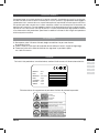
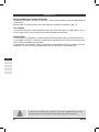
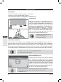
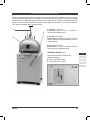
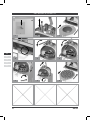
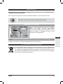
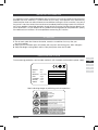
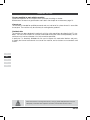
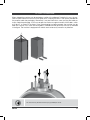
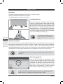
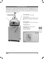
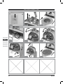
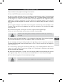
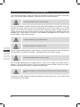
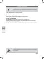
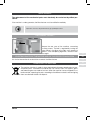
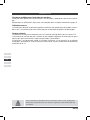
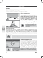
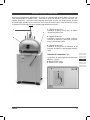
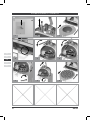
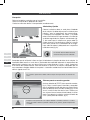
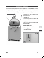
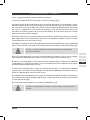
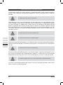
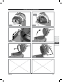
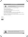
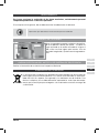
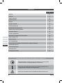
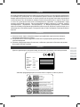
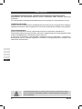
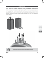
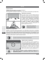
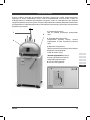
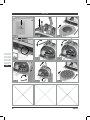
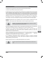
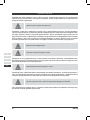
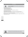
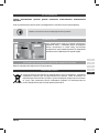
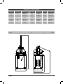
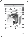
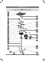
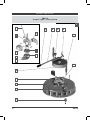
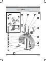
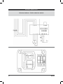
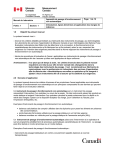
hidraulyc
SPA SA
mechanic
hidraulyc
mechanic
hidraulyc
hidraulyc
hidraulyc
mechanic
SPEZZATRICI ARROTONDATRICI SEMIAUTOMATICHE
SEMI-AUTOMATIC BUN DIVIDER
MACHINES D’ARRONDISSAGE SEMIAUTOMATIQUES
DIVISORAS BOLEADORAS OLEODINAMICAS SEMI-AUTOMATICAS
ПОЛУАВТОМАТИЧЕСКИЕ ТЕСТОДЕЛИТЕЛЬНЫЕ И ОКРУГЛИТЕЛЬНЫЕ МАШИНЫ
.ITALIANO
SPA SA
INDICE
PAG.
ITA
ENG
FRA
ESP
РУС
comportamenti
05
targhe
05
generalità
06
sollevamento della macchina
07
installazione
08
ricevimento
08
livellamento e fissaggio
08
allacciamento elettrico
08
primo avviamento e test
08
descrizione della macchina
09
pannello comandi
09
uso sicuro e corretto
10
valutazione dei risultati
12
pulizia della macchina
13
pulizia della testa spezzatrice e dei coltelli
13
manutenzione
17
tensione della cinghia motore
17
guasti elettrici del motore e del sistema di protezione
17
rottamazione della macchina
17
dati tecnici
73
ricambi
74
schema elettrico
82
SIMBOLI GRAFICI UTILIZZATI NEL MANUALE
Avvertenze di particolare importanza per la corretta esecuzione
delle operazioni descritte o di pericolo.
Operazioni che possono eseguire gli addetti all’uso della
macchina in quanto non richiedono specifiche qualifiche
Operazioni che devono essere eseguite solo da personale
specializzato.
04
SPA SA
COMPORTAMENTI
Conoscere bene le istruzioni contenute in questo manuale è importante per trarre il massimo profitto dall’uso della macchina ed è essenziale per la vostra sicurezza. Ogni operatore deve leggere e
capire bene tutto il manuale d’uso e manutenzione prima di cominciare ad usare questa macchina.
Se qualche parte del manuale non è chiara contattare subito il costruttore prima di cominciare ad
operare con la macchina. Per ogni problema relativo al funzionamento non esitate a contattare direttamente la Ditta Costruttrice: uno staff di tecnici è a vostra disposizione per ogni problema relativo
al funzionamento e alla produzione. Specificare il modello e il numero di serie in ogni corrispondenza
relativa a questa macchina.
ATTENZIONE!
1. Non operare sotto l’influenza di alcool, droghe o medicine che possano alterare
le condizioni fisiche.
2. Tenere i capelli e le altre parti del corpo ben lontani dalle parti rotanti, cinghie ed ingranaggi.
3. Tenere ben pulite ed in ordine le etichette che segnalano un pericolo e quelle
con i dati di sicurezza.
TARGHE
Dati relativi alla produzione, immatricolazione, conformità alle norme e all’alimentazione elettrica:
ITA
ENG
FRA
ESP
MODELLO
Model
DATA
Date
MATRICOLA
Serial Number
PESO
Weight
VOLTAGGIO
Voltage
POTENZA
Power
AMPERE
Ampere
РУС
Etichette relative alla segnalazione di pericolo o di divieto di particolari operazioni:
SPA SA
05
GENERALITÀ
.Persone qualificate a svolgere le funzioni
Produzione: per operare con questa macchina è necessario possedere la normale preparazione di
un panettiere.
Manutenzione: le qualifiche necessarie sono esposte al capitolo manutenzione, pag. 16.
.Uso corretto
La macchina è destinata a personale qualificato e non deve essere posta in luoghi aperti a tutti. La
macchina può essere usata solo per la lavorazione di prodotti di panetteria.
.Rischi residui
La macchina è stata progettata in conformità alle norme di sicurezza descritte nelle normative CE.
L’utilizzo della macchina in situazioni e modalità diverse da quelle previste dal costruttore può costituire rischi non prevedibili né quantificabili.
In particolare è assolutamente vietato all’utilizzatore manomettere dispositivi ed organi meccanici,
modificare la struttura interna ed esterna della macchina, allentare o svitare bulloni e viti.
ITA
ENG
FRA
ESP
РУС
A macchina in movimento tutti i coperchi, carter, ripari e protezioni devono essere
adeguatamente fissati alle rispettive strutture ed integri nella loro funzionalità.
06
SPA SA
SOLLEVAMENTO DELLA MACCHINA
La macchina può essere spedita imballata con pallet e cartone. La macchina imballata in questo
modo può essere sollevata con muletto o transpallet infilando i rebbi negli appositi spazi predisposti
sotto l’imballo stesso. Oppure può essere sollevata mediante gru facendo passare le funi o le fasce
sotto l’imballo. In questo caso rispettare l’angolo massimo di tensioni delle funi che deve essere di
45° come rappresentato in figura. Una volta tolto l’imballo la macchina può essere sollevata con una
gru; in tal caso utilizzare due golfari da avvitare sulla parte superiore della struttura come indicato
nella figura. La macchina è dotata di ruote e può essere spostata facilmente in ogni direzione.
ITA
ENG
FRA
ESP
РУС
Il sollevamento deve essere effettuato esclusivamente da personale qualificato.
SPA SA
07
INSTALLAZIONE
.Ricevimento
.Rimuovere l’imballo e controllare che non vi siano danni.
.Liberare la macchina dai bloccaggi sulla base.
.Contestare eventuali danni al trasportatore, immediatamente.
.Livellamento
Collocare la macchina su un pavimento piano. Intorno alla macchina devono essere lasciati gli spazi sufficienti per il lavoro e le operazioni di manutenzione. La
macchina è dotata di ruote e può essere facilmente
posizionata nel luogo desiderato. Il livellamento si ottiene regolando i piedini antivibranti (fig. 1), facendo in
modo che la macchina non appoggi sulle ruote durante il funzionamento. Montare la maniglia di pressione nel contenitore degli ingranaggi sulla testata e
bloccarla con l’apposito volantino (fig.1a).
.1
ITA
L’allacciamento elettrico deve essere
eseguito esclusivamente
da personale qualificato.
.1a
ENG
FRA
ESP
РУС
.Allacciamento elettrico
Assicurarsi che la linea abbia lo stesso voltaggio che è indicato sulla targhetta della macchina. L’alimentazione deve essere fatta attraverso un sezionatore di capacità adatta alla richiesta di potenza
della macchina, con una presa trifase a quattro contatti (3 fasi + terra). Collegarsi ai morsetti del quadro elettrico. Prima di dare tensione alla macchina assicurarsi che non vi siano collegamenti allentati
a causa del trasporto. Il collegamento deve essere fatto in conformità alle norme vigenti nel Paese.
Le operazioni a seguire devono essere affidate al personale
che esegue l’allacciamento elettrico.
.Primo avviamento e test
.2
Premere il pulsante di START (vedi pannello comandi
fig.4). Abbassare la maniglia di formatura e verificare
che il senso di rotazione del piatto sia quello della
freccia(senso orario) come indicato a lato (fig.2). Se
ciò non avvenisse invertire i due fili delle fasi.Eseguire
almeno una volta l’intero ciclo di lavoro senza usare
l’impasto. Per fermare la macchina premere il pulsante di STOP (vedi pannello comandi fig.4).
Qualsiasi guasto procurato alla macchina da manovre errate o manomissioni
eseguite durante il periodo coperto dalla garanzia, può compromettere
la validità della stessa.
08
SPA SA
DESCRIZIONE DELLA MACCHINA
Macchina particolarmente adatta alla spezzatura e formatura di pane arrotondato. Struttura in acciaio elettrosaldata e verniciata a forno; coltelli in acciaio inox AISI 304; testata in alluminio anticorodal
alimentare; piatti in policarbonato alimentare per una lunga durata. Sistema di arrotondamento che
replica il movimento della mano dell’uomo per trattare dolcemente l’impasto. Ciclo di lavoro pressatura, taglio e arrotondamento azionati da leve.
1
3
2
1. Maniglia di pressione.
Premendola verso il basso si esercita lo
schiacciamento della pasta.
2. Maniglia spezzatrice
Spingendola verso destra la testata si alza e i
coltelli si abbassano, provocando la spezzatura dell’impasto.
3. Maniglia di formatura
Abbassandola si avvia e si mantiene il processo di formatura (arrotondamento).
.Pannello comandi (Fig.4)
ITA
Il pannello comandi è composto dai
seguenti elementi:
4. Pulsante di START (nero)
5. Pulsante di STOP (rosso).
ENG
FRA
ESP
РУС
5
4
.4
SPA SA
09
USO SICURO E CORRETTO
.1
.2
.3
.4
.5
.6
.7
.8
.9
ITA
ENG
FRA
ESP
РУС
10
SPA SA
USO SICURO E CORRETTO
Fasi da seguire per il buon funzionamento della macchina:
1. Premere il pulsante di START per avviare la macchina (fig.1);
2. R
egolare la cloche di controllo del peso (fig. 2) in base al peso dell’impasto richiesto. La posizione della cloche determina il volume delle camere di formatura ed è perciò regolato sulla base del
peso dell’impasto che deve essere tagliato. Poiché la corretta regolazione dipende dalla consistenza
dell’impasto, la regolazione stessa è una questione di esperienza. Se il volume finale delle camere
di formatura è troppo esiguo, le palle di pasta risulteranno danneggiate. Se il volume è eccessivo, le
palle di pasta non verranno formate a sufficienza;
3. Mettere il pezzo d’impasto nel mezzo del piatto di formatura e appiattirlo manualmente, allargandolo sul piatto. Fare attenzione a non far uscire l’impasto dalle nicchie circolari. Spolverare la parte
superiore dell’impasto con un po’ di farina;
4. Inserire il piatto di formatura, assicurandosi che rimanga disteso sul tavolo di formatura (fig.3).
Fare attenzione che il perno di centraggio entri correttamente nel foro del piatto (fig.4);
Attenzione: se il piatto di formatura viene inserito in modo scorretto, la macchina
può essere gravemente danneggiata.
ITA
5. Abbassare la maniglia di pressione e premerla, comprimendo così l’impasto. Una volta completata
l’operazione di compressione, non sollevare la maniglia, ma tenerla in quella posizione (fig.5);
ENG
6. Tagliare l’impasto spingendo la maniglia spezzatrice verso destra (fig.6); eseguendo questa operazione si sgancerà il coltello: abbassare ulteriormente la maniglia di pressione fino a fine corsa in modo
da avere la certezza di aver tagliato completamente l’impasto;
ESP
7. P
er dare inizio alla formatura, abbassare leggermente la maniglia di formatura (fig.7). L’operazione
di stampaggio continua finché la maniglia è abbassata. Il tempo di formatura ottimale viene stabilito
per esperienza e dipende dalla consistenza dell’impasto;
8. Finita la fase di arrotondamento, riportare la maniglia di formatura in posizione neutra (attendere
che il piatto di formatura si fermi) quindi sollevare e riportare in posizione neutra anche la maniglia di
pressione (fig.8);
9. Estrarre il piatto di formatura con i pezzi arrotondati (fig.9).
Attenzione! In qualunque momento è possibile fermare la macchina premendo il
pulsante di STOP.
SPA SA
11
FRA
РУС
VALUTAZIONE DEI RISULTATI
Le seguenti informazioni vi aiuteranno ad ottenere il risultato desiderato. Quando la macchina è in
funzione, usare sempre le tre opzioni di regolazione: volume, tempo di pressione e tempo di formatura.
Le palle di pasta non hanno peso uguale
Assicurarsi che l’impasto sia posto nel centro del piatto e appiattito manualmente. Allargarlo un po’
sul piatto, ma sempre uniformemente e non lasciandolo mai uscire dalle nicchie circolari. Se questo
dovesse succedere, ve ne accorgerete nel momento in cui l’anello di pressione si abbassa: i pezzi di
impasto esterni all’anello non vengono né pressati né formati. Controllare il tempo di pre-lievitazione
dell’impasto (che dipende dal tipo di impasto ma di solito si aggira intorno ai 15 minuti). Premere l’impasto un po’ più a lungo o premerlo con più forza. Ciò darà all’impasto uno spessore più uniforme.
Le palle di pasta non sono completamente formate
Le palle di pasta hanno una superficie irregolare
ITA
ENG
FRA
ESP
Spostare la cloche di controllo del peso in una posizione più bassa. Aumentare il tempo di formatura
quando si aziona la maniglia di formatura, o utilizzare entrambi queste opzioni. L’impasto risulterà
formato più uniformemente.
РУС
Le palle di pasta non hanno una superficie liscia
Spostare la cloche di controllo del peso in una posizione più alta. Controllare che il peso dell’impasto
da tagliare sia conforme alla capacità della macchina. Le palle di pasta sono state formate con troppa forza; diminuire il tempo di formatura quando si aziona la maniglia di formatura.
La macchina comprime l’impasto nella fessura tra l’anello e il piatto di formatura.
L’impasto è stato compresso troppo a lungo. Diminuire il tempo di pressatura o usate minor forza
quando si aziona la maniglia di pressione.
12
SPA SA
PULIZIA DELLA MACCHINA
.2A
.1
.2
ITA
ENG
.2A
FRA
.3
ESP
РУС
.4
SPA SA
.5
13
PULIZIA DELLA MACCHINA
Le seguenti operazioni possono essere eseguite dal personale che utilizza
la macchina nel normale ciclo di lavoro.
Per pulire accuratamente i coltelli agire nel seguente modo:
.Togliere il carter superiore (fig.1):
Svitare le viti di fissaggio laterali;
.Estrarre il perno di bloccaggio (fig.2 (2A));
.Aprire la testa della macchina facendola ruotare di 90° fino a fine corsa (fig.3);
.Per una pulizia più accurata:
.Togliere l’anello di pressione girandolo di un quarto di giro verso destra (fig.4);
.Fare uscire il coltello sganciando la maniglia spezzatrice e abbassando la maniglia di pressione
(fig.5).
Si può usare un raschietto di plastica per l’operazione di pulizia.
Poi ungere leggermente la testa e i coltelli con olio alimentare. Non dimenticare di pulire anche
l’anello di pressione.
ITA
ENG
FRA
ESP
РУС
I pezzi di pasta che siano eventualmente rimasti attaccati alla macchina non devono
essere rimossi con la macchina in movimento.
14
SPA SA
MANUTENZIONE
Per quanto concerne la sostituzione dei pezzi meccanici deve essere assolutamente effettuata da personale competente.
Se la macchina è in garanzia ne deve essere dato immediato avviso al Costruttore stesso.
Operazioni che devono essere eseguite solo da personale qualificato.
TENSIONE DELLA CINGHIA
Togliere il carter posteriore della macchina svitando le
apposite viti di fissaggio. La cinghia si regola agendo
sulla vite mostrata in figura a lato; utilizzare una chiave
inglese per tenderla. A regolazione avvenuta, fissare
nuovamente il carter posteriore.
ITA
GUASTI ELETTRICI DEL MOTORE E DEL SISTEMA DI PROTEZIONE
ENG
Chiedere l’intervento di un elettricista o contattare la Ditta Costruttrice
FRA
ESP
ROTTAMAZIONE DELLA MACCHINA
La struttura della macchina è costruita in lamiera verniciata con vernice a polvere epossidica oppure con vernice a bicomponenti. I coltelli sono costruiti in acciaio inox AISI
304. i supporti, gli ingranaggi e i riduttori sono in ghisa. Ai fini della rottamazione la macchina deve essere separata nelle sue parti di diversa natura costruttiva da consegnare
alle strutture di smaltimento autorizzate.
SPA SA
15
РУС
.ENGLISH
SPA SA
CONTENTS
PAG.
ITA
ENG
FRA
ESP
РУС
important information
19
identification plates
19
general notice
20
lifting the machine
21
installation
22
on delivery
22
positioning
22
electrical connection
22
first start-up and test
22
machine description
23
control panel
23
safe and correct use
24
evaluating results
26
cleaning the machine
27
maintenance
29
electric faults of the motor and of the protection system
29
scrapping the machine
29
technical data
73
spare parts
74
wiring diagram
82
GRAPHIC SYMBOLS USED IN THE MANUAL
Particularly important warnings for the correct performance of the operation
described or danger warnings
Operations that may be performed by the machine operators as they
do not require specific qualifications
Operations that must be performed only by specialised personnel
18
SPA SA
IMPORTANT INFORMATION
It is important to have a good knowledge of the instructions in this manual in order to make the most
profitable use of the machine; it is also essential for your safety. Each operator must read and fully
understand the whole use and maintenance manual before starting to use this machine. If any part of
the manual is not clear, contact the manufacturer immediately before starting to work with the machine. For any problem concerning operation, do not hesitate to contact the Manufacturer directly: our
staff of technicians is at your disposal for any problem concerning operation and production. Specify
the model and serial number in all correspondence concerning this machine.
ATTENTION!
1. Do not work under the influence of alcohol, narcotics or medicines that may alter your
physical condition.
2. Keep your hair and other parts of the body well away from the rotating parts, belts and gears.
3. Keep the danger warning labels and the safety data plates clean and in order.
IDENTIFICATION PLATES
Data concerning production, serial number, conformity with standards and the electric power supply:
ITA
ENG
FRA
ESP
MODELLO
Model
DATA
Date
MATRICOLA
Serial Number
PESO
Weight
VOLTAGGIO
Voltage
POTENZA
Power
AMPERE
Ampere
РУС
Labels indicating danger or prohibiting particular operations:
SPA SA
19
GENERAL NOTICE
.Persons qualified to work with the machine
Production: operators on this machine must have normal training as a baker.
Maintenance: the necessary qualifications are listed in the chapter on maintenance, page 16.
.Correct use
The machine is intended for qualified personnel and must not be left in a place where it is accessible
to everyone. The machine may be used only for making bakery products.
.Residual risks
The machine has been designed in conformity with the safety regulations described in the EC standards. The use of the machine in situations and modes other than those contemplated by the manufacturer may involve unforeseen risks that cannot be quantified.
In particular it is absolutely forbidden for the user to tamper with mechanical devices and parts,
to modify the internal and external structure of the machine, and to slacken or unscrew bolts and
screws.
ITA
ENG
FRA
ESP
РУС
When the machine is running all the covers, casings, guards and protections must be
adequately secured to their respective structures, with all their functions intact.
20
SPA SA
LIFTING THE MACHINE
When shipped the machine may be packed on a pallet with cardboard. Packed in this way, the machine may be lifted with a fork-lift truck or pallet truck, inserting the forks in the spaces provided for
the purpose under the packaging. Alternatively it may be lifted with a crane, passing the cables or
straps under the packaging. In this case respect the maximum angle of tension of the cables, which
must be 45° as shown in the figure. Once the packaging has been removed, the machine may be
lifted with a crane; in this case use two eyebolts, screwed onto the top of the structure as indicated
in the figure. The machine is equipped with wheels and can be easily moved in any direction.
The machine may be lifted exclusively by qualified personnel.
SPA SA
21
INSTALLATION
.On delivery
.Remove the packaging and check that there is no sign of damage.
.Free the machine from the blocks on the base.
.Immediately report any damage to the carrier.
.Levelling and fixing
Place the machine on a flat floor surface. Sufficient
space must be left around the machine to allow work
and maintenance operations. The machine is equipped with wheels and can be easily positioned in the
desired place. It is levelled by regulating the vibrationdamping feet (fig. 1), ensuring that the machine does
not rest on the wheels while operating. Fit the pressure handle in the gear container on the head and block
it with the handwheel provided (fig.1a).
.1
ITA
The electrical connection must be
made exclusively by qualified personnel.
.1a
ENG
FRA
ESP
РУС
.Electrical connection
Ensure that the line has the same voltage indicated on the machine data plate. Power must be supplied through a disconnecting switch with a capacity suitable for the machine power requirement,
using a three-phase socket with four contacts (3 phases + earth). Connect to the electric panel terminals. Before powering the machine, ensure that no connections have worked loose during transport.
The connection must be made in conformity with the regulations in force in the country of use.
The following operations must be entrusted to the personnel making the electrical
connection.
.First start-up and test
.2
Press the START button (see control panel, fig.4).
Lower the forming handle and check that the plate
is turning in the direction of the arrow (clockwise), as
indicated at the side (fig.2). Otherwise invert the two
phase wires. Perform the whole work cycle at least
once without using the dough. To stop the machine
press the STOP button (see control panel, fig.4).
Any fault caused to the machine by incorrect manoeuvres or by tampering during the
period in which it is covered by the guarantee may affect its validity.
22
SPA SA
MACHINE DESCRIPTION
Machine particularly suitable for dividing and forming round loaves. Electrowelded and stove-enamelled steel structure; blades made of AISI 304 stainless steel; head in anticorodal aluminium suitable for foodstuffs; polycarbonate plates suitable for foodstuffs, to ensure long life. Rounding system
which repeats the movement of the human hand to treat the dough gently. Pressing, cutting and
rounding work cycles carried out by levers.
1
3
2
1. Pressure handle
Press it down to crush the dough.
2. Dividing handle
When pushed to the right, the head is raised
and the blades are lowered, dividing the dough.
3. Forming handle
Lower it to start and maintain the forming process (rounding).
.Control panel (Fig.4)
ITA
The control panel is composed of the
following elements:
4. START button (black)
5. STOP button (red).
ENG
FRA
ESP
РУС
5
4
.4
SPA SA
23
SAFE AND CORRECT USE
.1
.2
.3
.4
.5
.6
.7
.8
.9
ITA
ENG
FRA
ESP
РУС
24
SPA SA
SAFE AND CORRECT USE
Steps to follow for the proper functioning of the machine:
1. Press the START button to start the machine (fig.1);
2. Adjust the weight regulating rod (fig. 2) according to the desired dough weight. The regulating rod
position determines the volume of the forming chambers, so it is regulated according to the weight
of the dough that is to be cut. Since the correct adjustment depends on the dough consistency,
regulating is a matter of experience. If the final volume of the forming chambers is too small, the
balls of dough will be damaged. If the volume is excessive, the balls of dough will not be sufficiently
formed;
3. Put the piece of dough in the middle of the forming plate and flatten it by hand, spreading it over
the plate. Take care not to let the dough get out of the circular hollows. Dust the top of the dough
with a little flour;
4. Insert the forming plate, ensuring that it remains lying on the forming table (fig.3).
Make sure that the centring pin correctly enters the hole in the plate (fig.4);
Attention: if the forming plate is incorrectly inserted, the machine may be seriously
damaged.
ITA
5. Lower the pressure handle and press it, thus compressing the dough. Once the pressing operation has been completed, do not lift the handle but keep it in that position (fig.5);
ENG
6. Cut the dough, pushing the dividing handle to the right (fig.6); when this operation is performed,
the blade will be released: lower the handle further, as far as it will go, to ensure that the dough has
been completely cut;
ESP
7. To start forming, slightly lower the forming handle (fig.7). The moulding operation continues as
long as the handle is down. T
he optimum forming time is established by experience and depends
on the consistency of the dough;
8. When the rounding phase is finished, return the forming handle to neutral position (wait until the
forming plate stops), then raise also the pressure handle and return it to neutral position (fig.8);
9. Extract the forming plate with the rounded pieces (fig.9).
Attention! The machine can be stopped at any time by pressing the STOP button.
SPA SA
25
FRA
РУС
EVALUATING RESULTS
The following information will help you obtain the desired result. When the machine is operating,
always use the three regulating options: volume, pressure time and forming time.
The balls of dough do not have the same weight.
Ensure that the dough is placed in the centre of the plate and flattened by hand. Spread it a little over
the plate, but always evenly and never let the dough get out of the circular hollows. If this should
happen, you will notice the moment the pressure ring is lowered: the pieces of dough outside the
ring are not pressed or formed. Check the pre-rising time of the dough (which depends on the type
of dough, but is usually around 15 minutes). Press the dough a bit longer or press it harder. This will
give the dough a more uniform thickness.
The balls of dough are not completely formed.
The balls of dough have an irregular surface.
ITA
ENG
FRA
Shift the weight regulating rod into a lower position. Increase the forming time when activating the
forming handle, or use both these options. The dough will be more uniformly formed.
ESP
The balls of dough do not have a smooth surface.
РУС
Shift the weight regulating rod into a higher position. Check that the weight of the dough to be cut
conforms with the machine capacity. The balls of dough have been formed with too much force;
decrease the forming time when activating the forming handle.
The machine compresses the dough into the crack between the ring and the forming
plate.
The dough has been compressed too long. Decrease the pressing time or use less force when
activating the pressure handle.
26
SPA SA
CLEANING THE MACHINE
.2A
.1
.2
ITA
ENG
.2A
FRA
.3
ESP
РУС
.4
SPA SA
.5
27
CLEANING THE MACHINE
The following operations may be performed by the personnel who use the machine
during the normal work cycle.
To clean the blades accurately, proceed as follows:
.Remove the top case (fig.1):
Unscrew the fixing screws at the side;
.Extract the blocking pin (fig.2 (2A));
.Open the machine head, turning it through 90° to end of travel (fig.3);
.For more accurate cleaning:
.Remove the pressure ring, turning it a quarter of a turn to the right (fig.4);
.Bring out the blade by releasing the dividing handle and lowering the pressure handle (fig.5).
A plastic scraper may be used for cleaning.
Then lightly oil the head and blades with edible oil. Do not forget to clean the pressure ring too.
ITA
ENG
FRA
ESP
РУС
Any pieces of dough that have been left stuck to the machine must not be removed
when it is moving.
28
SPA SA
MAINTENANCE
The replacement of the mechanical parts must absolutely be carried out by skilled personnel.
If the machine is under guarantee, the Manufacturer must be notified immediately.
Operations that must be performed only by qualified personnel.
TIGHTENING THE BELT
Remove the rear case of the machine, unscrewing
the fixing screws. The belt is regulated by turning the
screw shown in the figure at the side; use a spanner to
tighten it. After completing regulation, secure the rear
case again.
ELECTRIC FAULTS OF THE MOTOR AND OF THE PROTECTION SYSTEM
Ask for the intervention of an electrician or contact the Manufacturer
FRA
ESP
SCRAPPING THE MACHINE
The machine structure is made of sheet steel painted with epoxy powder paint or twocomponent paint. The blades are made of AISI 304 stainless steel. The supports, gears
and reduction gears are made of cast iron. When the machine is to be scrapped it must
be dismantled, separating the parts according to the different materials and consigning
them to authorised facilities for disposal.
SPA SA
ITA
ENG
29
РУС
.FRANÇAIS
SPA SA
TABLE DES MATIÈRES
PAG.
ITA
ENG
FRA
ESP
РУС
comportements
33
plaques
33
généralités
34
levage de la machine
35
installation
36
réception
36
positionnement
36
branchement électrique
36
première mise en service et test
36
description de la machine
37
panneau de commandes
38
utilisation sûre et correcte
39
évaluation des résultats
41
nettoyage de la machine
42
maintenance
43
pannes électriques du moteur et du système de protection
43
mise hors service de la machine
43
données techniques
73
pièces de rechange
74
schéma électrique
82
SYMBOLES GRAPHIQUES UTILISÉS DANS LE MANUEL
Recommandations particulièrement importantes pour l’exécution correcte
des opérations décrites ou de danger.
Opérations que peuvent exécuter les personnes préposées à l’utilisation
de la machine dans la mesure où elles ne demandent pas de qualifications
spécifiques
Opérations qui sont réservées exclusivement au personnel spécialisé.
32
SPA SA
COMPORTEMENTS
Bien connaître les instructions contenues dans ce manuel est important pour tirer le profit maximum
de l’utilisation de la machine et est essentiel pour votre sécurité. Chaque opérateur doit lire et bien
comprendre toutes les instructions d’utilisation et de maintenance avant de commencer à utiliser
cette machine. Si une partie quelconque du manuel n’est pas claire, contacter immédiatement le
constructeur avant de commencer à opérer avec la machine. Pour tout problème relatif au fonctionnement, n’hésitez pas à contacter directement le constructeur : une équipe de techniciens est à
votre disposition pour tout problème relatif au fonctionnement et à la production. Préciser le modèle
et le numéro de série dans toute correspondance relative à cette machine.
ATTENTION !
1. Ne pas opérer sous l’influence d’alcool, de drogues ou de médicaments susceptibles
d’altérer les conditions physiques.
2. Maintenir les cheveux et les autres parties du corps loin des parties en rotation, des courroies
et des engrenages.
3. Maintenir bien propres et en bon état les étiquettes qui signalent un danger et celles qui
contiennent les données de sécurité.
PLAQUES
ITA
Données relatives à la production, à l’immatriculation, à la conformité aux normes
et à l’alimentation électrique :
ENG
FRA
ESP
MODELLO
Model
DATA
Date
MATRICOLA
Serial Number
PESO
Weight
VOLTAGGIO
Voltage
POTENZA
Power
AMPERE
Ampere
РУС
Étiquettes relatives à la signalisation de danger ou d’interdiction d’opérations particulières:
SPA SA
33
GÉNÉRALITÉS
.Personnes qualifiées pour l’exécution des fonctions
Production: pour opérer avec cette machine il faut posséder la préparation normale d’un boulanger.
Maintenance: les qualifications nécessaires sont indiquées dans le chapitre maintenance, page 16.
.Utilisation correcte
La machine est destinée au personnel qualifié et ne doit pas être placée dans des endroits accessibles à tous. La machine ne peut être utilisée que pour la fabrication de produits de boulangerie.
.Risques résiduels
La machine a été conçue en conformité avec les critères de sécurité décrits dans les normes CE.
L’utilisation de la machine dans des situations et des modalités différentes de celles prévues par le
constructeur peut constituer des risques non prévisibles ni quantifiables.
En particulier, il est absolument interdit à l’utilisateur d’intervenir sur les dispositifs et les organes
mécaniques, de modifier la structure interne et externe de la machine, de desserrer ou de dévisser
les boulons et les vis.
ITA
ENG
FRA
ESP
РУС
Avec la machine en mouvement, tous les couvercles, carters, écrans et protections
doivent être correctement fixés aux structures respectives et leur fonctionnalité doit
être intacte.
34
SPA SA
LEVAGE DE LA MACHINE
La machine peut être expédiée emballée dans un carton sur palette. La machine ainsi emballée
peut être levée par un chariot élévateur ou un transpalette en enfilant les fourches dans les espaces
prévus à cet effet sous l’emballage. En alternative, elle peut être levée par une grue en faisant passer
les élingues ou les sangles sous l’emballage. Dans ce cas, respecter l’angle maximum de tension
des élingues qui doit être de 45° comme indiqué sur la figure. Une fois déballée, la machine peut être
levée par une grue ; dans ce cas utiliser deux œillets à visser sur la partie supérieure de la structure
comme indiqué dans la figure. La machine est équipée de roues et peut être facilement déplacé
dans n’importe quelle direction.
ITA
ENG
FRA
ESP
РУС
Le levage doit être effectué exclusivement par du personnel qualifié.
SPA SA
35
INSTALLATION
.Réception
.Enlever l’emballage et contrôler qu’il n’y a aucun dommage.
.Libérer la machine des blocages sur la base.
.Contester immédiatement les éventuels dommages au transporteur.
.Mise de niveau et fixation
Placer la machine sur un sol plat. Laisser autour de la
machine suffisamment d’espace pour le travail et les
opérations de maintenance. La machine est munie
de roues et peut être facilement positionnée à l’endroit désiré. La mise de niveau s’obtient en agissant
sur les vérins réglables antivibratoires (fig. 1), en veillant que la machine ne soit pas en appui sur les roues durant le fonctionnement. Monter la poignée de
pression dans la boîte des engrenages sur la tête et la
bloquer avec le volant prévu à cet effet (fig. 1a).
.1
ITA
ENG
FRA
ESP
РУС
Le branchement électrique doit être
exécuté exclusivement par du personnel qualifié.
.1a
.Branchement électrique
Contrôler que la ligne a le même voltage que celui qui est indiqué sur la plaquette de la machine.
L’alimentation doit être faite en intercalant un sectionneur d’une capacité adaptée à la demande de
puissance de la machine, avec une prise triphasée à quatre contacts (3 phases + terre). Se connecter
aux bornes du tableau électrique. Avant d’alimenter la machine, contrôler qu’aucune connexion ne
s’est desserrée à cause du transport. La connexion doit être effectuée conformément aux normes en
vigueur dans le pays.
Les opérations qui suivent doivent être confiées au personnel qui effectue le branchement électrique.
.Première mise en service et test
.2
Presser le bouton START (voir panneau de commande fig.4). Abaisser la poignée de formage et vérifier
que le plateau tourne bien dans le sens de la flèche
(sens horaire) comme indiqué ci-contre (fig.2). Si ce
n’est pas le cas, inverser les deux fils des phases.
Exécuter au moins une fois un cycle de travail complet sans pâte. Pour arrêter la machine presser le
bouton STOP (voir panneau de commande fig.4).
Tout dommage provoqué à la machine par des manœuvres erronées ou des manipulations effectuées durant la période couverte par la garantie peut compromettre la
validité de cette dernière.
36
SPA SA
DESCRIPTION DE LA MACHINE
Machine particulièrement adaptée pour la division et l’arrondissage de pains boules. Structure en
acier électrosoudée et laquée au four ; couteaux en acier inox AISI 304 ; tête en aluminium anticorodal alimentaire ; plateaux en polycarbonate alimentaire assurant une longue durée. Système
d’arrondissage reproduisant le mouvement de la main de l’homme pour traiter doucement la pâte.
Cycle de travail pressage, coupe et arrondissage actionnés par leviers.
1
3
2
1. Poignée de pression.
Quand on la presse vers le bas, on obtient
l’écrasement de la pâte.
2. Poignée de division
Quand on la pousse vers la droite, la tête remonte et les couteaux s’abaissent, en provoquant la division de la pâte.
3. Poignée de formage
Quand on la baisse, on fait démarrer et on
maintient le processus de formage (arrondissage).
ITA
.Panneau de commande (Fig.4)
Le panneau de commande est composé des
éléments suivants:
4. Bouton START (noir)
5. Bouton STOP (rouge).
ENG
FRA
ESP
РУС
5
4
.4
SPA SA
37
UTILISATION SÛRE ET CORRECTE
.1
.2
.3
.4
.5
.6
.7
.8
.9
ITA
ENG
FRA
ESP
РУС
38
SPA SA
UTILISATION SÛRE ET CORRECTE
Étapes à suivre pour le bon fonctionnement de la machine:
1. Presser le bouton START pour mettre en marche la machine (fig. 1);
2. Régler la tige de contrôle du poids (fig. 2) suivant le poids de pâte désiré. La position de la tige
détermine le volume des chambres de formage et est donc réglée sur la base du poids de la pâte
qui doit être coupée. Dans la mesure où le réglage correct dépend de la consistance de la pâte, le
réglage proprement dit est une question d’expérience. Si le volume final des chambres de formage
est trop restreint, les boules de pâte résulteront endommagées. Si le volume est excessif, les boules
de pâte ne seront pas correctement formées;
3. Mettre le morceau de pâte au centre du plateau de formage et l’aplatir manuellement en l’élargissant sur le plateau. Faire attention à ne pas faire sortir la pâte des niches circulaires. Saupoudrer un
peu de farine sur le dessus de la pâte;
4. Positionner le plateau de formage, en veillant qu’il soit bien à plat sur la table de formage (fig. 3).
Veiller que le pivot de centrage entre correctement dans le trou du plateau (fig. 4);
Attention: si le plateau de formage est mal positionné, la machine peut être gravement endommagée.
ITA
5. Abaisser la poignée de pression et la presser, en comprimant ainsi la pâte. Quand l’opération de
compression est terminée, ne pas relever la poignée, mais la maintenir dans cette position (fig. 5);
ENG
6. Couper la pâte en poussant la poignée de division vers la droite (fig. 6) ; cette opération provoque
le décrochage du couteau : baisser ultérieurement la poignée de pression jusqu’à la fin de la course
de manière à être sûr d’avoir coupé complètement la pâte;
ESP
7. P
our commencer le formage, abaisser légèrement la poignée de formage (fig. 7). L’opération de
moulage continue tant que la poignée est abaissée. Le temps de formage optimal est établi par
expérience et dépend de la consistance de la pâte;
8. Quand la phase d’arrondissage est terminée, reporter la poignée de formage en position neutre
(attendre que le plateau de formage s’arrête) puis relever la poignée de pression et la remettre en
position neutre (fig. 8);
9. Extraire le plateau de formage avec les boules de pâte (fig. 9).
Attention ! À tout moment, il est possible d’arrêter la machine en pressant la touche
STOP.
SPA SA
39
FRA
РУС
ÉVALUATION DES RÉSULTATS
Les informations qui suivent vous aideront à obtenir le résultat désiré. Quand la machine est en
fonction, utiliser toujours les trois options de réglage : volume, temps de pression et temps de formage.
Les boules de pâte n’ont pas le même poids.
Contrôler que la pâte est bien placée au centre du plateau et aplatie manuellement. L’étendre un
peu sur le plateau, mais toujours de manière uniforme et en ne la laissant jamais sortir des niches
circulaires. Si cela devait se produire, on s’en rend compte au moment où l’anneau de pression
s’abaisse : les morceaux de pâte débordant de l’anneau ne sont ni pressés ni formés. Contrôler le
temps de préfermentation de la pâte (qui dépend du type de pâte mais qui habituellement tourne
autour de 15 minutes). Presser la pâte un peu plus longtemps ou la presser avec plus de force. Cela
donnera une épaisseur plus uniforme.
Les boules de pâte ne sont pas complètement formées.
ITA
Les boules de pâte ont une surface irrégulière.
ENG
FRA
ESP
Déplacer la tige de contrôle du poids dans une position plus basse. Augmenter le temps de formage
quand on actionne la poignée de formage, ou utiliser ces deux options. Les boules de pâte seront
formées de manière plus uniforme.
РУС
Les boules de pâte n’ont pas une surface lisse
Déplacer la tige de contrôle du poids dans une position plus haute. Contrôler que le poids de la pâte
à couper est conforme à la capacité de la machine. Les boules de pâte ont été formées avec trop de
force ; diminuer le temps de formage quand on actionne la poignée de formage.
La machine comprime la pâte dans la fissure entre l’anneau et le plateau
de formage.
La pâte a été comprimée trop longtemps. Diminuer le temps de pressage ou actionner la poignée
de pression avec moins de force.
40
SPA SA
NETTOYAGE DE LA MACHINE
.2A
.1
.2
ITA
ENG
.2A
FRA
.3
ESP
РУС
.4
SPA SA
.5
41
NETTOYAGE DE LA MACHINE
Les opérations qui suivent peuvent être effectuées par le personnel qui utilise la machine dans le cycle normal de travail.
Pour nettoyer parfaitement les couteaux procéder de la façon suivante:
.Enlever le carter supérieur (fig. 1):
Dévisser les vis de fixation latérales;
.Extraire le axe de blocage (fig. 2 (2A));
.Ouvrir la tête de la machine en la faisant tourner de 90° jusqu’à la fin de course (fig. 3).
.Pour un nettoyage plus approfondi:
.Enlever l’anneau de pression en le tournant d’un quart de tour vers la droite (fig. 4) ;
.Faire sortir le couteau en décrochant la poignée de division et en abaissant la poignée de pression
(fig. 5).
On peut utiliser un racloir en plastique pour l’opération de nettoyage.
Huiler ensuite légèrement la tête et les couteaux avec de l’huile alimentaire. Ne pas oublier de nettoyer aussi l’anneau de pression.
ITA
ENG
FRA
ESP
РУС
Les pâtons qui sont restés éventuellement collés à la machine ne doivent pas être
enlevés quand la machine est en mouvement.
42
SPA SA
MAINTENANCE
Le remplacement des pièces mécaniques doit être effectué exclusivement par du personnel compétent.
Si la machine est sous garantie, le constructeur doit en être averti immédiatement.
Opérations qui sont réservées exclusivement au personnel qualifié.
TENSION DE LA COURROIE
Enlever le carter arrière de la machine en dévissant les
vis de fixation. La courroie se règle en agissant sur la vis
indiquée dans la figure ci-contre ; utiliser une clé anglaise pour la tendre. Une fois le réglage effectué, fixer de
nouveau le carter arrière.
ITA
PANNES ÉLECTRIQUES DU MOTEUR ET DU SYSTÈME DE PROTECTION
ENG
Demander l’intervention d’un électricien ou contacter le Constructeur
FRA
ESP
MISE HORS SERVICE DE LA MACHINE
La structure de la machine est construite en tôle laquée avec peinture à poudre époxy
ou peinture bicomposants. Les couteaux sont en acier inox AISI 304. Les supports, les
engrenages et les réducteurs sont en fonte. Lors de la mise hors service, la machine
doit être démantelée en séparant les parties suivant les différents matériaux qui devront
être remis aux structures de recyclage autorisées.
SPA SA
43
РУС
.ESPAÑOL
SPA SA
ÍNDICE
PAG.
ITA
ENG
FRA
ESP
РУС
comportamientos
47
placas
47
información general
48
elevación de la máquina
49
instalación
50
recepción
50
colocación
50
conexión eléctrica
50
primera puesta en marcha y prueba
50
descripción de la máquina
51
panel de mandos
52
utilización segura y correcta
53
evaluación de los resultados
54
limpieza de la máquina
55
mantenimiento
57
averías eléctricas del motor y del sistema de protección
57
eliminación de la máquina
57
datos técnicos
73
recambios
74
esquema eléctrico
82
SÍMBOLOS GRÁFICOS UTILIZADOS EN EL MANUAL
Advertencia particularmente importante para la correcta ejecución de las
operaciones descritas o de peligro.
Operaciones que pueden efectuar los usuarios de la máquina puesto
que no requieren una cualificación específica
Operaciones que debe efectuar exclusivamente personal especializado.
46
SPA SA
COMPORTAMIENTOS
Un buen conocimiento de las instrucciones contenidas en este manual es importante para obtener
el máximo provecho de la máquina y es fundamental para su seguridad. Todo operador debe leer
y entender todo el manual de uso y mantenimiento antes de empezar a utilizar esta máquina. Si
alguna parte del manual no está clara, póngase en contacto inmediatamente con el fabricante antes
de empezar a trabajar con la máquina. No dude en ponerse en contacto directamente con el fabricante ante cualquier problema de funcionamiento: un equipo de técnicos está a su disposición para
resolver todo problema de funcionamiento y producción. Especifique el modelo y el número de serie
en toda comunicación que se refiera a esta máquina.
¡ATENCIÓN!
1. No trabaje bajo los efectos de alcohol, drogas o medicamentos que puedan alterar las
condiciones físicas.
2. Mantenga los cabellos y las demás partes del cuerpo lejos de partes giratorias,
correas y engranajes.
3. Mantenga bien limpias y en orden las etiquetas que señalan un peligro y las que contienen
datos de seguridad.
PLACAS
Datos correspondientes a producción, matrícula, conformidad con normas y suministro eléctrico:
ITA
ENG
FRA
ESP
MODELLO
Model
DATA
Date
MATRICOLA
Serial Number
PESO
Weight
VOLTAGGIO
Voltage
POTENZA
Power
AMPERE
Ampere
РУС
Etiquetas con señales de peligro o de prohibición de determinadas operaciones:
SPA SA
47
INFORMACIÓN GENERAL
.Personas cualificadas para desarrollar las funciones
Producción: para trabajar con esta máquina es necesario poseer la preparación normal de un panadero.
Mantenimiento: la necesaria formación se indica en el capítulo mantenimiento, pág. 16.
.Uso correcto
La máquina está destinada a personal cualificado y no debe ponerse en sitios al alcance de todos.
La máquina puede ser utilizada exclusivamente para realizar productos de panadería.
.Riesgos residuales
La máquina ha sido diseñada en conformidad con las normas de seguridad descritas en las normas
CE. La utilización de la máquina en situaciones y modos diferentes de los previstos por el fabricante
puede acarrear riesgos no previsibles ni cuantificables.
En especial se prohíbe terminantemente al usuario forzar dispositivos y órganos mecánicos, modificar la estructura interior y exterior de la máquina, aflojar o destornillar tornillos y roscas.
ITA
ENG
FRA
ESP
РУС
Con la máquina en movimiento todas las tapas, cárter, resguardos y protecciones
tienen que estar adecuadamente fijados a las respectivas estructuras e íntegros para
su funcionamiento.
48
SPA SA
ELEVACIÓN DE LA MÁQUINA
La máquina se puede enviar embalada con palet y caja. La máquina embalada de esta manera se
puede levantar con carretilla elevadora o transpaleta introduciendo las horquillas en los específicos
espacios previstos bajo el embalaje. O bien se puede izar utilizando una grúa haciendo pasar los
cables o las eslingas por debajo del embalaje. En este caso respétese el ángulo máximo de tensiones de los cables que debe ser de 45° como ilustrado en la figura. Una vez sacado el embalaje, la
máquina puede ser izada con una grúa; en este caso utilizar dos armellas que se atornillarán en la
parte superior de la estructura como indicado en la figura. La máquina está equipada con ruedas y
puede moverse fácilmente en cualquier dirección.
ITA
ENG
FRA
ESP
РУС
La elevación debe efectuarla exclusivamente personal cualificado.
SPA SA
49
INSTALACIÓN
.Recepción
.Retirar el embalaje y controlar que no haya daños.
.Soltar la máquina de los bloqueos de la base.
.Contestar eventuales daños al transportador, inmediatamente.
.Nivelación y fijación
.1
ITA
ENG
FRA
ESP
РУС
.1a
Colocar la máquina sobre un suelo plano. Alrededor
de la máquina se debe dejar espacio suficiente para
trabajar y para las operaciones de mantenimiento.
La máquina está equipada con ruedas y se puede
colocar fácilmente en el lugar deseado. La nivelación
se obtiene regulando los soportes antivibratorios (fig.
1), de manera que la máquina no apoye sobre las
ruedas durante el funcionamiento. Montar la manilla
para hacer presión en el contenedor de los engranajes sobre el cabezal y bloquearla con la específica
rueda de mano (fig.1a).
La conexión eléctrica debe efectuarla
exclusivamente personal cualificado.
.Conexión eléctrica
Comprobar que el voltaje de la línea sea igual al indicado en la plaquita de datos de la máquina. La
acometida debe hacerse a través de un seccionador de capacidad adecuada al requerimiento de
potencia de la máquina, con una toma trifásica con cuatro contactos (3 fases + tierra). Conectarse
a los bornes del cuadro eléctrico. Antes de conectar la tensión en la máquina, comprobar que no
haya conexiones aflojadas debido al transporte. La conexión se debe hacer en conformidad con las
normas vigentes en el País.
Las siguientes operaciones deben confiarse al personal que efectúe la conexión eléctrica.
.Primera puesta en marcha y prueba
.2
Accionar el botón de START (véase panel de mandos,
fig. 4). Bajar la manilla para el formado y comprobar
que el sentido de rotación del plato sea el de la flecha
(hacia la derecha) como se indica al lado (fig.2). De no
ser así, invertir los dos hilos de las fases. Realizar una
vez, como mínimo, el entero ciclo de trabajo sin utilizar
masa. Para detener la máquina, accionar el botón de
STOP (véase panel de mandos, fig. 4).
Cualquier avería provocada a la máquina debido a maniobras erróneas o a alteraciones efectuadas durante el periodo cubierto por la garantía, puede comprometer
su validez.
50
SPA SA
DESCRIPCIÓN DE LA MÁQUINA
Máquina particularmente apropiada para la división y la formación de pan redondeado. Estructura
de acero electrosoldada y pintada en horno; cuchillas de acero inoxidable AISI 304; cabezal de
aluminio anticorodal para uso alimentario; platos de policarbonato para uso alimentario de larga duración. Sistema de redondeo que reproduce el movimiento de la mano humana para un tratamiento
delicado de la masa. Ciclo de trabajo prensado, corte y redondeo accionados por palancas.
1
3
2
1. Manilla de presión
Al accionarla hacia abajo se efectúa el aplastamiento de la masa.
2. Manilla divisora
Al empujarla hacia la derecha, el cabezal sube
y las cuchillas bajan, lo que provoca la división
de la masa.
3. Manilla de formado
Al bajarla, inicia y se mantiene el proceso de
formado (redondeo).
.Panel de mandos (Fig.4)
ITA
Componen el panel de mandos los
elementos siguientes:
4. Botón de START (negro)
5. Botón de STOP (rojo).
ENG
FRA
ESP
РУС
5
4
.4
SPA SA
51
UTILIZACIÓN SEGURA Y CORRECTA
.1
.2
.3
.4
.5
.6
.7
.8
.9
ITA
ENG
FRA
ESP
РУС
52
SPA SA
UTILIZACIÓN SEGURA Y CORRECTA
Pasos a seguir para el buen funcionamiento de la máquina:
1. Accionar el botón de START para poner en marcha la máquina (fig.1);
2. R
egular la palanca de control del peso (fig. 2) en función del peso de la masa requerida. La posición de la palanca determina el volumen de las cámaras de formado y por ello se regula en función
del peso de la masa que se debe cortar. Como la correcta regulación depende de la consistencia
de la masa, su regulación es una cuestión de experiencia. Si el volumen final de las cámaras de
formado es insuficiente, las bolas de masa resultarán dañadas. Si el volumen es excesivo, las bolas
de masa no se formarán por completo;
3. Poner el trozo de masa en el centro del plato de formado y aplanarlo manualmente, ensanchándolo sobre el plato. Prestar atención para que la masa no salga de los espacios circulares. Distribuir
un poco de harina por la encima de la masa;
4. Introducir el plato de formado, comprobar que permanezca extendido sobre la mesa de formado
(fig.3). Prestar atención a que el perno de centrado entre correctamente en el orificio del plato (fig.4);
Atención: si el plato de formado se introduce incorrectamente, se puede dañar
gravemente la máquina.
ITA
5. Bajar la manilla de presión y presionar, comprimiendo de esta manera la masa. Una vez completada la operación de compresión, no elevar la manilla, mantenerla en esa posición (fig.5);
ENG
6. Cortar la masa empujando la manilla divisora hacia la derecha (fig.6); al efectuar esta operación
se desengancha la cuchilla: bajar todavía más la manilla de presión hasta el tope para estar seguros
de haber cortado completamente la masa;
ESP
7. Para iniciar el formado, bajar un poco la manilla de formado (fig.7). La operación de modelado
sigue mientras se mantiene la manilla bajada. El tiempo de formado óptimo se establece con la experiencia y depende de la consistencia de la masa;
8. Acabada la fase de redondeo, volver a poner la manilla de formado en posición neutra (esperar a
que el plato de formado se detenga) luego levantar y colocar de nuevo en posición neutra también
la manilla de presión (fig.8);
9. Extraer el plato de formado con las porciones redondeadas (fig.9).
¡Atención! Es posible detener la máquina en todo momento, accionando el botón
di STOP.
SPA SA
53
FRA
РУС
EVALUACIÓN DE LOS RESULTADOS
La información siguiente le ayudará a obtener el resultado deseado. Para el funcionamiento de la
máquina, utilizar siempre las tres opciones de regulación: volumen, tiempo de presión y tiempo de
formado.
Las bolas de masa no tienen el mismo peso.
Comprobar que la masa haya sido colocada en el centro del plato y haya sido aplanada manualmente. Extender un poco sobre el plato, pero siempre uniformemente y no dejando que salga de
los huecos circulares. Si sucediera esto, se dará cuenta en el momento en que baja el anillo de
presión: las porciones de masa por fuera del anillo ni se prensan ni se forman. Controlar el tiempo
de pre-fermentación de la masa (que depende del tipo de masa pero que normalmente son unos
15 minutos). Presionar la masa por más tiempo o presionar con más fuerza. Esto dará mayor uniformidad a la masa.
Las bolas de masa no se forman completamente.
ITA
Las bolas de masa tienen una superficie irregular.
ENG
FRA
ESP
Desplazar la palanca de control del peso a una posición inferior. Aumentar el tiempo de formado tras
accionar la manilla de formado. Utilizando estas dos opciones, la masa resultará más uniformemente
formada.
РУС
Las bolas de masa no tienen una superficie lisa
Desplazar la palanca de control del peso a una posición superior. Controlar que el peso de la masa
que se corta sea conforme con la capacidad de la máquina. Las bolas de masa se han formado
ejerciendo demasiada fuerza; disminuir el tiempo de formado tras accionar la manilla de formado.
La máquina comprime la masa en la ranura entre el anillo y el plato de formado.
La masa ha sido comprimida demasiado tiempo. Disminuir el tiempo de prensado o hacer menos
fuerza al accionar la manilla de presión.
54
SPA SA
LIMPIEZA DE LA MÁQUINA
.2A
.1
.2
ITA
ENG
.2A
FRA
.3
ESP
РУС
.4
SPA SA
.5
55
LIMPIEZA DE LA MÁQUINA
Las siguientes operaciones pueden ser efectuadas por el personal que utiliza la
máquina durante el ciclo de trabajo normal.
Para limpiar cuidadosamente las cuchillas, actuar en el modo siguiente:
.Sacar el resguardo superior (fig.1):
Destornillar los tornillos de fijación laterales;
.Extraer los perno de bloqueo (fig.2 (2A));
.Abrir el cabezal de la máquina haciendo que gire 90° hasta el tope (fig.3);
.Para una limpieza más profunda:
.Sacar el anillo de presión, girándolo un cuarto de vuelta hacia la derecha (fig.4);
.Hacer salir la cuchilla, desenganchando la manilla divisora y bajando la manilla de presión (fig.5).
Se puede usar una rasqueta de plástica para la operación de limpieza.
Seguidamente untar un poco el cabezal y las cuchillas con aceite para uso alimentario. No olvidar
limpiar también el anillo de presión.
ITA
ENG
FRA
ESP
РУС
Las porciones de masa que eventualmente hubieran quedado pegadas a la máquina
no deben sacarse mientras la máquina esté en movimiento.
56
SPA SA
MANTENIMIENTO
Por lo que concierne la sustitución de las piezas mecánicas, exclusivamente personal
competente puede llevar a cabo esta operación.
Si la máquina está en garantía, ello se debe comunicar inmediatamente al fabricante.
Operaciones que debe efectuar exclusivamente personal cualificado.
TENSADO DE LA CORREA
Sacar el resguardo trasero de la máquina, destornillando los específicos tornillos de fijación. La correa se
regula actuando en el tornillo mostrado en la figura al
lado; utilizar una llave inglesa para tensarla. Una vez
efectuada la regulación, fijar de nuevo el resguardo trasero.
ITA
AVERÍAS ELÉCTRICAS DEL MOTOR Y DEL SISTEMA DE PROTECCIÓN
ENG
Solicitar la intervención de un electricista o interpelar al fabricante
FRA
ESP
ELIMINACIÓN DE LA MÁQUINA
La estructura de la máquina está realizada con chapa pintada con pintura epoxi en
polvo o bien con pintura bicomponente. Las cuchillas están realizadas en acero inoxidable AISI 304. Los soportes, los engranajes y los reductores son de fundición. Para
eliminar la máquina, ésta se debe desmontar separando los varios tipos de componentes que la constituyen para entregarlos a las autorizadas estructuras encargas de
su eliminación.
SPA SA
57
РУС
.РУССКИЙ
SPA SA
СОДЕРЖАНИЕ
PAG.
правила
61
таблички
61
общие описания
62
подъем агрегата
63
монтаж
64
порядок приемки
64
позиционирование
64
электрическое подключение
64
первый запуск и тестирование
64
описание агрегата
65
консоль управления
65
безопасная и правильная эксплуатация
66
ITA
оценка результатов
68
ENG
чистка агрегата
69
FRA
тех. обслуживание
71
ESP
электрические неисправности двигателя и защитной системы
71
РУС
утилизация агрегата
71
технические данные
73
запасные части
74
электрическая схема
82
ГРАФИЧЕСКИЕ СИМВОЛЫ, ИСПОЛЬЗУЕМЫЕ В ТЕХ. РУКОВОДСТВЕ
Предупреждения особой важности для правильного выполнения
описанных работ или предупреждения об опасности.
Работы, выполняемые персоналом, эксплуатирующим агрегат, не
нуждающимся в специальной квалификации
Работы, выполняемые только квалифицированным персоналом.
60
SPA SA
ПРАВИЛА
Для наиболее эффективной эксплуатации агрегата важно хорошо знать инструкции, приведенные
в настоящем тех. руководстве, что также является крайне важным и для Вашей безопасности.
Каждый рабочий должен прочитать и хорошо усвоить все инструкции настоящего руководства
по эксплуатации и тех. обслуживанию перед началом эксплуатации данного агрегата. Если какаято часть тех. руководства малопонятна, незамедлительно обратитесь к производителю перед
началом эксплуатации агрегата. При возникновении проблем, связанных с работой агрегата,
незамедлительно обращайтесь непосредственно на Фирму-производитель: технический
персонал в Вашем распоряжении для решения любых вопросов, связанных с работой агрегата и с
производством. Указывайте модель и заводской номер во всех сообщениях, касающихся Вашего
агрегата.
ВНИМАНИЕ!
1. Не использовать агрегат в нетрезвом виде, под воздействием наркотиков или лекарств,
влияющих на физическое состояние.
2. Не приближаться головой и другими частями тела к вращающимся деталями, ремням и
зубчатым передачам.
3. Этикетки, предупреждающие об опасности, и таблички с данными по безопасности должны
быть всегда чистыми и целыми.
ТАБЛИЧКИ
ITA
Данные о дате выпуска, заводской номер, соответствие нормативам и тип электропитания:
ENG
FRA
ESP
MODELLO
Model
DATA
Date
MATRICOLA
Serial Number
PESO
Weight
VOLTAGGIO
Voltage
POTENZA
Power
AMPERE
Ampere
РУС
Этикетки, предупреждающие об опасности или о запрете на какие-то работы:
SPA SA
61
ОБЩИЕ ОПИСАНИЯ
.Квалифицированный персонал, уполномоченный выполнять следующие работы
Производство: для эксплуатации данного агрегата необходимо иметь обычную подготовку
хлебопека.
Тех. обслуживание: необходимая квалификация указана в разделе тех. обслуживание на стр. 16.
.Порядок эксплуатации
Агрегат расчитан на эксплуатацию квалифицированным персоналом и не должен быть помещен в
общедоступном месте. Агрегат предназначен только для производства хлебобулочных изделий.
.Остаточная опасность
Агрегат спроектирован согласно правилам безопасности, описанным в нормативах СЕ.
Эксплуатация агрегата в случаях и в целях, отличных от предусмотренных производителем, может
создать непредвиденную и неописанную здесь опасность.
В частности, пользователю категорически запрещается вносить изменения в устройства и
механические органы, изменять внутреннюю и внешнюю конструкции агрегата, ослаблять или
отвинчивать болты и винты.
ITA
ENG
FRA
ESP
РУС
При работающем агрегате все крышки, кожухи, картеры и предохранения должны
быть прикреплены надлежащим образом к соответствующим структурам и
быть исправными.
62
SPA SA
ПОДЪЕМ АГРЕГАТА
Агрегат может быть доставлен упакованным в картон на деревянном поддоне. Агрегат,
упакованный таким образом, можно поднимать автопогрузчиком или виловым погрузчиком,
вставив вилы в специальные проемы под поддоном. Агрегат так же можно поднять подъемным
краном, пропустив стропы или тросы под упаковкой. В этом случае соблюдайте максимальный
угол натяжения строп - 45°, как показано на схеме. Сняв упаковку с агрегата, можно поднять его
подъемным краном; в этом случае используйте два рым-болта, ввинчиваемые в верхнюю часть
структуры, как показано на схеме. Машина оснащена колесами и могут быть легко перемещены
в любую сторону.
ITA
ENG
FRA
ESP
РУС
Осуществлять подъем должен только квалифицированный персонал.
SPA SA
63
МОНТАЖ
.Порядок приемки
.Снимите упаковку и проверьте отсутствие повреждений.
.Снимите блокировки агрегата в основании.
.При обнаружений повреждений незамедлительно обращайтесь с рекламацией к грузоперевозчику.
.Нивелировка и крепление
Расположите агрегат на ровном полу. Вокруг агрегата
необходимо оставить достаточно пространства для
работы и тех. обслуживания. Агрегат укомплектован
колесиками, на которых его можно легко разместить
в нужном месте. Нивелировка производится
посредством регуляции антивибрационных ножек
(сх. 1) таким образом, чтобы агрегат не опирался
на колесики в процессе функционирования.
Установить прижимную рукоятку на коробку
зубчатых передач на головке и зафиксировать ее
специальным маховиком (сх. 1а).
.1
ITA
ENG
FRA
ESP
РУС
Осуществлять электрические
подсоединения должен только
квалифицированный персонал.
.1a
.Электрическое подключение
Проверить, чтобы линия электропитания имела то же напряжение, которое указано на шильдике
агрегата. На линии электропитания должен быть установлен размыкатель мощностью, рассчитанной
на мощность агрегата, с трехфазной сетевой вилкой с 4 контактами (3 фазы + заземление). Выполнить
подсоединение к клеммам электрического щита. Перед запитыванием агрегата проверить, чтобы
соединения не были ослаблены в процессе транспортировки. Соединения должны соответствовать
нормативам, действующим в стране эксплуатации агрегата.
Следующие операции должны выполняться электромонтером.
.Первый запуск и тестирование
.2
Нажать кнопку START (см. консоль управления, сх.
4). Опустить рукоятку формовки и проверить, чтобы
направление вращения диска совпадало со стрелкой
(по часовой стрелке), как показано сбоку (сх. 2). В
противном случае поменять местами два провода
фаз. Выполнить не менее одного раза полный
рабочий цикл без теста. Для остановки агрегата
нажать кнопку STOP (см. консоль управления, сх. 4).
Любое повреждение агрегата по причине неправильных операций или
вмешательств, выполненных в гарантийный период, может привести к
аннулированию гарантии.
64
SPA SA
ОПИСАНИЕ АГРЕГАТА
Агрегат особенно пригоден для деления и формовки закрученного хлеба. Электросваренная
структура из стали, покрашеная в печи; ножи из нержавеющей стали AISI 304; головка из
антикоррозийного алюминия для пищевых продуктов; лотки из поликарбоната для пищевых
продуктов длительного срока службы. Система заворачивания повторяет движение человеческих
рук для деликатного формирования теста. Рабочий цикл прессования, отрезания и заворачивания
управляется рычагами.
1
3
2
1. Прижимная рукоятка.
При ее нажиме происходит прессование
теста.
2. Тестоделительная рукоятка
Поворачивая рукоятку вправо, головка
поднимается, и ножи опускаются, разрезая
тесто.
3. Формовочная рукоятка
При ее опускании запускается и выполняется
формовка (заворачивание).
.Panel de mandos (Fig.4)
.Консоль управления (Схема 4)
Консоль управления состоит из
следующих комплетующих:
4. Кнопка START (черный)
5. Кнопка STOP (красная).
ITA
ENG
FRA
ESP
РУС
5
4
.4
SPA SA
65
МОНТАЖ
.1
.2
.3
.4
.5
.6
.7
.8
.9
ITA
ENG
FRA
ESP
РУС
66
SPA SA
ПРАВИЛЬНАЯ И БЕЗОПАСНАЯ ЭКСПЛУАТАЦИЯ
Последовательность действий для надлежащего функционирования машины:
1. Нажать кнопку START для запуска агрегата (схема 1);
2. Отрегулировать рычаг контроля веса (схема 2) в зависимости от требуемого веса теста. Положение
рычага определяет объем формовочных камер и поэтому регулируется по весу разрезаемого
теста. Так как правильная регуляция зависит от консистенции теста, результат регуляции зависит
от опыта. Если окончательный объем формовочных камер слишком мал, шарики теста получатся
деформированными. Если объем слишком велик, шарики теста не будут достаточно сформованы;
3. Поместить кусок теста в центр формовочного лотка и прижать его вручную, распределяя по
лотку. Следить, чтобы тесто не выходило за края круглых ячеек. Присыпать тесто сверху мукой.
4. Вставить формовочный лоток, проверив, чтобы он прочно оставался на формовочном столе
(схема 3).
Проверить, чтобы центровочный штифт правильно вошел в отверстие в диске (схема 4);
Внимание: если формовочный лоток устанавливается неправильно, агрегат
может подвергнуться серьезным повреждениям.
5. Опустить прижимную рукоятку и нажать на нее, прессуя таким образом тесто. По завершении
прессования не поднимать рукоятку, но удерживать ее в том же положении (схема 5);
6. Разрезать тесто, повернув рукоятку тестоделителя вправо (схема 6); при выполнении этой
операции освобождается нож: еще сильнее прижать прижимную рукоятку до упора для
обеспечения полного разрезания теста.
7. Для начала формовки слегка опустить формовочную рукоятку (схема 7). Формовка продолжится
до тех пор, пока будет опущена рукоятка. Оптимальная
продожительность
формовки
определяется на основании опыта и зависит от консистенции теста;
8. По завершении заворачивания вернуть формовочную рукоятку в исходное положение
(дождаться остановки формовочного лотка), затем поднять и перевести в исходное положение
также прижимную рукоятку (схема 8);
9. Вынуть формовочный лоток с завернутыми изделиями из теста (схема 9).
Внимание! Агрегат может быть остановлен в любой момент при помощи кнопки
STOP.
SPA SA
67
ITA
ENG
FRA
ESP
РУС
ОЦЕНКА РЕЗУЛЬТАТОВ
Приведенные ниже сведения помогут Вам получить оптимальный результат. При работающем
агрегате всегда использовать три аспекта регуляции: объем, продолжительность прессования и
продожительность формовки.
Шарики теста не имеют одинаковый вес
Проверить, чтобы тесто помещалось в центр лотка и расправлялось вручную. Слегка расправить
тесто в лотке однородно, не давая тесту выйти за пределы круглых ячеек. Если тесто выйдет из ячеек,
это будет заметно в момент опускания прессовального кольца: вышедшие наружу куски теста не
будут ни прессованы, ни формованы. Проверить продолжительность предварительной расстойки
теста (зависит от типа теста, но обычно составляет примерно 15 минут). Прижать тесто в течение
большего времени или с большей силой. Это придаст толщине теста большую однородность.
Шарики теста недоформованы
Неровная поверхность шариков теста
ITA
ENG
FRA
ESP
Перевести рычаг управления веса в самое нижнее положение. Увеличить продолжительность
формовки при использовании формовочной рукоятки или использовать обе эти операции. Тесто
получится сформованным более однородно.
РУС
Шероховатая поверхность шариков теста
Перевести рычаг управления веса в самое верхее положение. Проверить, чтобы вес разрезаемого
теста соответствовал вместимости агрегата. Шарики теста были сформованы с излишней силой;
сократить продолжительность формовки при использовании формовочной рукоятки.
Агрегат прессует тесто в прорезь между кольцом и формовочным диском.
Тесто прессовалось слишком долго. Сократить время прессования или применять меньшую силу
при использовании прижимной рукоятки.
68
SPA SA
ЧИСТКА АГРЕГАТА
.2A
.1
.2
ITA
ENG
.2A
FRA
.3
ESP
РУС
.4
SPA SA
.5
69
ЧИСТКА АГРЕГАТА
Следующие операции могут выполняться персоналом, эксплуатирующим агрегат
для обычного производства.
Порядок тщательной чистки ножей:
.Снять верхний картер (Схема 1):
Открутить боковые крепежные винты;
. Удалите стопорный штифт (рис. 2 (2А));
. Открыть Machine Head, повернув его на 90 градусов до упора (рис. 3);
.Для более тщательной чистки:
.Снять прижимное кольцо, повернув его на одну четвертую поворота вправо (схема 4);
.Выдвинуть нож, отцепив тестоделительную рукоятку и опустив прижимную рукоятку (схема 5).
Для чистки можно использовать пластиковый скребок.
Затем слегка смазать головку и ножи пищевым растительным маслом. Следует помнить также о
чистке прижимного кольца.
ITA
ENG
FRA
ESP
РУС
Не вынимайте куски теста, прилипшие к агрегату, в процессе его работы.
70
SPA SA
ТЕХ. ОБСЛУЖИВАНИЕ
Замену механических деталей должен выполнять исключительно компетентный
персонал.
Если гарантийный срок еще не истек, незамедлительно сообщите об этом Производителю.
Работы, выполняемые только квалифицированным персоналом.
НАТЯЖЕНИЕ РЕМНЯ
Снять задний картер агрегата, отвинтив специальные
крепежные винты. Натяжение ремня регулируется
винтом, показанным на схеме сбоку; используйте
разводной ключ для натяжения ремня. По завершении
регуляции вновь зафиксировать задний картер.
ITA
ЭЛЕКТРИЧЕСКИЕ НЕИСПРАВНОСТИ ДВИГАТЕЛЯ И ЗАЩИТНОЙ СИСТЕМЫ
ENG
Вызвать электрика или обратиться к Производителю.
FRA
ESP
УТИЛИЗАЦИЯ АГРЕГАТА
Структура агрегата изготовлена из металлического листа, покрашеного эпоксидной
порошковой краской или же двукомпонентной краской. Ножи изготовлены из
нержавеющей стали AISI 304. Суппорты, зубчатые передачи и редукторы изготовлены
из чугуна. При утилизации агрегат необходимо разделить на комплектующие из
разных материалов и сдать в центр приема утильсырья.
SPA SA
71
РУС
Dati tecnici / Technical data
Modello / Model
Divisioni / Divisions
Grammatura / Basis Weight
Capacità / Capacity
Pressino / Pressino
Potenza / Power
Dimensioni / Dimensions
SPA SA 15
15
100/260 gr
4 Kg
Ø 400x65h
0.55 Kw
64x64x145 cm
SPA SA 22
22
50/180 gr
4 Kg
Ø 400x65h
0.55 Kw
64x64x145 cm
SPA SA 30 s
30
25/90 gr
2,7 Kg
Ø 340x65h
0.55 Kw
64x64x145 cm
SPA SA 30
30
40/135 gr
4 Kg
Ø 400x65h
0.55 Kw
64x64x145 cm
SPA SA 36
36
34/110 gr
4 Kg
Ø 400x65h
0.55 Kw
64x64x145 cm
SPA SA 52
52
12/40 gr
2,08 Kg
Ø 340x65h
0.55 Kw
64x64x145 cm
2015
Ingombri generali della macchina / General cluttered of the machine
655
545
635
980
SPA SA
73
Ricambi / Spare Parts
TAV. 1
Gruppo Basamento / Base Group
16
17
12
14
15
13
11
10
5
6
4
3
7
2
8
74
1
9
SPA SA
Ricambi / Spare Parts
TAV. 1
Gruppo Basamento / Base Group
POS.
Q
Descrizione / Description
1
1
BASAMENTO / BASE
2
1
CARTER ANTERIORE / FRONT CASE
3
1
CARTER LATERALE DESTRO / RIGHT SIDE CASE
4
1
CARTER POSTERIORE / REAR CASE
5
1
CARTER SUPERIORE / UPPER CASE
6
1
CARTER LATERALE SINISTRO / LEFT SIDE CASE
7
1
PANNELLO COMANDO / CONTROL PANEL
8
4
PIEDINO DI APPOGGIO / FOOT SUPPORT
9
4
RUOTA / WHEEL
10
1
ANELLO ANTIFRIZIONE / ANTIFRICTION RING
11
1
SUPPORTO DESTRO / RIGHT SUPPORT
12
1
SUPPORTO SINISTRO / LRFT SUPPORT
13
1
PIOLO BATTUTA TESTA / HEAD REST PEG
14
1
PERNO FISSO / FIXED PIN
15
1
TAPPO / STOPPER
16
1
PERNO MOBILE / MOBILE PIN
17
1
MANIGLIA PERNO MOBILE / MOBILE PIN HANDLE
SPA SA
75
Ricambi / Spare Parts
TAV. 2
Gruppo Arrotondamento / Rounding Group
34
33
32
31
32
31
29
26
28
23
27
22
25
24
20
21
14
19
18
16
13
17
11
12
15
11
10
8
9
7
3
2
5
76
1
4
SPA SA
Ricambi / Spare Parts
POS.
Q
Descrizione / Description
1
1
FORCELLA / FORK
2
1
LEVA COMANDO ARROTONDAMENTO / ROUNDING CONTROL LEVER
3
1
IMPUGNATURA LEVA COMANDO ARROTONDAMENTO / ROUNDING CONTROL GRIP HANDLE
4
2
SUPPORTO SKF CON CUSCINETTO / SKF SUPPORT WITH BEARING
5
1
RULLO FORCELLA / FORK ROLLER
6
2
PERNO FORCELLA / FORK PIN
7
1
SUPPORTO PORTA FORCELLA / FORK HOLDER SUPPORT
8
1
CUSCINETTO 6204 2RS / BEARING 6204 2RS
9
1
MOLLA / SPRING
10
1
PERNO COMANDO ECCENTRICO / CAM CONTROL PIN
11
2
CUSCINETTO 6008 2RS / BEARING 6008 2RS
12
1
FLANGIA PORTA CUSCINETTI / BEARING HOLDER FLANGE
13
1
PULEGGIA / PULLEY
14
1
PULEGGIA MOTORE / MOTOR PULLEY
15
1
MOTORE / MOTOR
16
1
PERNO LAMIERA FISSAGGIO MOTORE / PIN PLATE MOTOR
17
1
LAMIERA FISSAGGIO MOTORE / MOTOR PLATE
18
1
CINGHIA / BELT
19
1
PERNO INFERIORE BIELLA / LOWER PISTON ROD PIN
20
1
BIELLA / PISTON ROD
21
1
PERNO SUPERIORE BIELLA / UPPER PISTON ROD PIN
22
2
ASTA GUIDA CARRELLO ECCENTRICO / GUIDE CARRIAGE ECCENTRIC SHAFT
23
2
BLOCCHETTO PORTA ASTE GUIDA / STROKE BAR HOLDER BLOCK
24
1
CARRELLO ECCENTRICO / ECCENTRIC SADDLE
25
4
SUPPORTO CON MANICOTTI / SUPPORT WITH SLEEVE
26
2
ASTA SCORRIMENTO / SLIDE BAR
27
1
CARRELLO PORTA MANICOTTI / SADDLE HOLDER SLEEVES
28
1
CUSCINETTO 6205 2RS / BEARING 6205 2RS
29
2
GUIDA PATTINO / RUNNER GUIDE
30
2
PATTINO / RUNNER
31
1
FLANGIA PORTA CUSCINETTO / BEARING HOLDER FLANGE
32
1
PIOLO RIFERIMENTO PIATTO / PINS REFERENCE PLATE
33
1
PIASTRA ARROTONDAMENTO / ROUNDING SLAB
34
2
BLOCCHETTO APPOGGIO / BLOCK SUPPORT
SPA SA
77
Ricambi / Spare Parts
TAV. 3
Gruppo Taglio / Cutting Group
A
4
15
6
B
16
17
14
13
A
5
2
3
1
7
12
11
7
9
8
78
SPA SA
Ricambi / Spare Parts
TAV. 3-3A
Gruppo Taglio / Cutting Group
POS.
Q
Descrizione / Description
1
1
PIATTO DI FORMATURA / MOLDING PLATE
2
1
ANELLO ESTERNO / EXTERNAL RING
3
1
COLTELLO / KNIFE
4
1
LEVA COMANDO PRESSATA/TAGLIO / LEVER PRESS/CUTTING
5
1
CARTER TESTATA ANTERIORE / FRONT HEAD CASE
6
1
CARTER TESTATA POSTERIORE / REAR HEAD CASE
7
1
TESTATA / HEAD
8
2
ROTELLA ANELLO / RING ROLLER
9
2
SUPPORTO SCORREVOLE / SLIDING SUPPORT
10
1
SUPPORTO PERNO CENTRALE / CENTRAL PIN SUPPORT
11
1
TAMPONE FINE CORSA / END OF STROKE STOPPER
12
1
COPERCHIO CENTRALE / CENTRAL COVER
13
2
ASTA GUIDA ANELLO / RING GUIDE BAR
14
1
MOLLA LEVA INNESTO TAGLIO / SPRING LEVER CUT ENGAGEMENT
15
1
MANIGLIA LEVA INNESTO TAGLIO / LEVER HANDLE SOCKET CUTTING
16
1
LEVA INNESTO TAGLIO / CUT CONNECTION LEVER
17
1
PERNO LEVA INNESTO TAGLIO / CUT CONNECTION LEVER PIN
SPA SA
79
Ricambi / Spare Parts
TAV. 3
Gruppo Taglio / Cutting Group
B
4
25
6
5
3
2
23
22
B
A
24
26
21
1
27
28
20
29
30
34
19
31
18
33
32
35
36
80
SPA SA
Ricambi / Spare Parts
TAV. 3B
Gruppo Taglio / Cutting Group
POS.
Q
Descrizione / Description
18
1
SUPPORTO TESTA / HEAD SUPPORT
19
2
ASTA SCORRIMENTO / SHIFT BAR
20
2
TAPPO MANIGLIA / HANDLE STOPPER
21
1
INGRANAGGIO CON PORTA LEVA PRESSATA-TAGLIO / GEAR LEVER WITH PORT PRESS-CUTTING
22
2
MOLLA A GAS TESTATA / HEAD GAS SPRING
23
2
ATTACCO MOLLA A GAS / GAS SPRING CONNECTION
24
2
VOLANTINO / HAND WHEEL
25
1
ASTA FINE CORSA / END OF STROKE BAR
26
1
NONIO / VERNIER
27
1
PERNO INGRANAGGIO / PIN GEAR
28
2
SUPPORTO ATTACCO CARTER / CASE CONNECTION SUPPORT
29
2
BLOCCHETTO FINECORSA / END OF STROKE BLOCK
30
2
PERNO SOSTEGNO LEVA / PIN LEVER SUPPORT
31
2
PATTINO ANELLO TESTATA / SHOE RING HEAD
32
2
LEVA ANELLO / LEVER RING
33
2
RULLO LEVA ANELLO / ROLLER LEVER RING
34
2
ATACCO ASTA / BAR CONNECTION
35
1
ALBERO CREMAGLIERA / SHELF SHAFT
36
1
SUPPORTO NONIO / VERNIER SUPPORT
SPA SA
81
Ricambi / Spare Parts
Schema elettrico / Outline electrical worker
82
SPA SA
SPA SA
CAPOZZO
CIRCUITO STAMPATO / PRINTED CIRCUIT
OELMA
OELMA
DADO NYLON / NYLON NUT
TELEMECANIQUE
PRESSACAVO NYLON / NYLON CABLE GLAND
CONTATTO APERTO LUMINOSO / LUMINOUS CONNECTION N.O.
HL1
TELEMECANIQUE
TELEMECANIQUE
PULSANTE DI MARCIA / START BUTTON
SB2
TELEMECANIQUE
OMEGA
FASTON DA CIRCUITO STAMPATO / FASTON FOR PRINTED CIRCUIT
CONTATTO CHIUSO / CONNECTION N.C.
A.B.B.
TELERUTTORE / REMOTE CONTROL SWITCH
PULSANTE DI EMERGENZA / EMERGENCY BUTTON
TEFMA
TRASFORMATORE 8 va 0.230.400/0.24 / TRANSFORMER 8VA 0.230.400/0.24
SB1
OMEGA
FUSIBILI / VOLTAGE FUSE
TC1
OMEGA
OMEGA
FUSIBILI / VOLTAGE FUSE
PORTAFUSIBILI UNIPOLARE / UNIPOLAR VOLTAGE FUSE HOLDER
OMEGA
GEWISS
Costruttore
PORTAFUSIBILI TRIPOLARE / TRIPOLAR VOLTAGE FUSE HOLDER
CASSETTA / BOX
Descrizione / Description
KM1
FU2
FU1
SIGLA
Modello
PG11
PG11 MAX
ZB4BWO31
ZB4BW333
ZB4BZ102
ZB4BS54
CC342
B7-30-10-P 24VAC
TF223
5x20 4A F IN VETRO
C1033
CS363
10x38 10A GL
Q13803
GW44209
2
3
1
1
1
1
16
1
1
2
1
1
6
1
1
Quantità
Ricambi / Spare Parts
Schema elettrico / Outline electrical worker
83
Le illustrazioni e i dati tecnici si intendono a titolo indicativo e non sono vincolanti. La Ditta Costruttrice si riserva il diritto di modificare, senza preavviso, i dati tecnici e le caratteristiche dei prodotti in qualsiasi momento al solo scopo di migliorare le caratteristiche. / Pictures, explanations and technical details are supplied
in indicative mood and without any time bond. Consequently the Machine Manifaturer has the right to make changes, without notice, for the sake of improving
the products or for any constructive or commercial requirement.