1
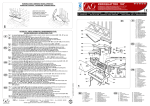
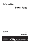
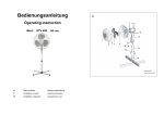
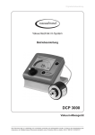
Information
Power Parts
76012955033
04. 2011
3.211.849
*3211849*
www.ktm.com
DEUTSCH
Danke, dass Sie sich für KTM Power Parts entschlossen haben.
Alle unsere Produkte wurden nach den höchsten Standards entwickelt und gefertigt, unter Verwendung der besten verfügbaren
Materialien.
KTM Power Parts sind rennerprobt und gewährleisten ultimative Performance.
KTM KANN NICHT VERANTWORTLICH GEMACHT WERDEN FÜR FALSCHE MONTAGE ODER VERWENDUNG DIESES PRODUKTS. Bitte
befolgen Sie die Montageanleitung. Fachmännische Beratung und korrekte Installation der KTM PowerParts durch einen autorisierten
KTM Händler sind unerlässlich, um das Optimum an Sicherheit und Funktionalität zu gewährleisten.
Danke.
ENGLISH
2
Thank you for choosing KTM Power Parts!
All of our products are designed and built to the highest standards using the finest materials available.
KTM Power Parts are race proven to offer the ultimate in performance.
KTM WILL NOT BE HELD LIABLE FOR IMPROPER INSTALLATION OR USE OF THIS PRODUCT. Please follow all instructions provided.
Professional advice and proper installation of the KTM PowerParts by an authorized KTM dealer are essential to provide maximum
safety and functions.
Thank you.
ITALIANO
2
Grazie per aver deciso di acquistare un prodotto KTM Power Parts.
Tutti i nostri prodotti sono stati sviluppati e realizzati secondo i massimi standard e con l'impiego dei migliori materiali disponibili.
Le KTM Power Parts sono collaudate nelle competizioni ed assicurano altissime prestazioni.
KTM NON PUÒ ESSERE RESA RESPONSABILE PER UN MONTAGGIO O USO IMPROPRIO DI QUESTO PRODOTTO. Per favore osservate le
istruzioni nel manuale d'uso. Al fine di garantire la massima sicurezza e il corretto funzionamento, è indispensabile farsi consigliare
da persone esperte e competenti e far eseguire l'installazione delle KTM PowerPart presso i concessionari KTM autorizzati.
Grazie.
FRANCAIS
2
Nous vous remercions d'avoir choisi KTM Power Parts.
Tous nos produits ont été développés et réalisés selon les plus hauts standards et en utilisant les meilleurs matériaux disponibles.
Les Power Parts de KTM ont fait leurs preuves en compétition et garantissent les meilleures performances.
LA RESPONSABILITÉ DE KTM NE SAURAIT ÊTRE ENGAGÉE EN CAS D'ERREUR DANS LE MONTAGE OU L'UTILISATION DE CE PRODUIT.
Il convient de respecter les instructions de montage.
Le conseil spécialisé et l'installation dans les règles de l'art des PowerParts KTM par un concessionnaire KTM agréé sont
indispensables pour assurer un maximum de sécurité et de fonctionnalité.
Merci.
ESPANOL
2
2
Gracias por haberse decidido por el Power Parts KTM.
Todos nuestros productos han sido desarrollados y producidos según los estándares más altos utilizando los mejores materiales
disponibles.
Las KTM Power Parts están probadas en competencia y garantizan un óptimo rendimiento.
NO SE PUEDE HACER RESPONSABLE A LA KTM POR UN MONTAJE O UN USO INCORRECTO DE ESTE PRODUCTO.
Le rogamos seguir las instrucciones para el montaje.
A fin de garantizar la máxima seguridad y un funcionamiento correcto es imprescindible acudir a un concesionario autorizado de KTM
para obtener el mejor asesoramiento técnico e instalar correctamente las KTM PowerParts.
Gracias.
3
1
7600498004430
76012955010
76012955020
7600392300033
2
Vorarbeiten
4
- Beide Gabeln ausbauen (siehe Reparaturanleitung).
- Federbein ausbauen (siehe Reparaturanleitung).
- Original Seitenständer demontieren.
Montage
6
- Gabelservice durchführen
5
Gabelservice
-
Gabelbein ausbauen (siehe Reparaturanleitung).
Gabelbein im unteren bereich einspannen.
HINWEIS:
Klemmblock T612S (5) (optional erhältlich) verwenden.
-
Schraubdeckel (6) lösen.
- Schraubdeckel (6) gegenhalten und von der Kolbenstange (7) lösen.
6
- Schraubdeckel (6) entfernen.
7
- Gabelöl entleeren.
- Außenrohr vom Innenrohr entfernen.
HINWEIS:
Auffanggefäß unterstellen, da meist noch etwas Öl ausläuft.
DEUTSCH
Lieferumfang:
1x Winkelhebel (1)
2x Buchse 12,3x21,5x20 (2)
2x Buchse 37x50 (3)
1x Seitenständer (4)
3
- Restliches Öl entleeren.
DEUTSCH
4
- Außenrohr im Bereich der unteren Gabelbrücke einspannen.
8
HINWEIS:
Klemmblock T612S (4) (optional erhältlich) verwenden.
- Staubmanschette (8) entfernen.
5
- Sicherungsring (9) entfernen.
9
HINWEIS:
Der Sicherungsring hat ein angeschliffenes Ende, an dem ein Schraubendreher
angesetzt werden kann.
- Außenrohr im Bereich des Dichtrings (10) etwas erwärmen (Bild A).
Vorgabe: 50°C
A
- Dichtring (10) entfernen.
10
- Stützring (11) entfernen.
11
Vorgabe: 50°C
DEUTSCH
- Außenrohr im Bereich der Gleitbuchse (12) erwärmen.
5
- Gabelaußenrohr mit dem unteren Rand auf eine Holzplatte klopfen.
HINWEIS:
Die Gleitbuchse (12) muss dabei aus ihrem Lagersitz fallen.
12
- Gabelbeine kontrollieren.
HINWEIS:
Neue Buchsen und Dichtringe verwenden.
12
- Kanten der neuen Gleitbuchsen (12) mit Schleifpapier Körnung 600
anschleifen, reinigen und schmieren (Gabelöl SAE 5).
- Außenrohr im Bereich der unteren Gabelbrücke einspannen.
HINWEIS:
Klemmblock T612S (5) (optional erhältlich) verwenden.
-
Neue Gleitbuchse (12) einpressen.
- Innenrohr (13) mit Bremsenreiniger reinigen und für 60 Sek. erwärmen,
um das Loctite zu lösen.
7
Vorgabe: 50°C
14
- Kolbenstange (7) vom Innenrohr (13) demontieren.
HINWEIS:
Stiftschlüssel T103 (14) (optional erhältlich) verwenden.
13
Achtung, das Kolbenstangenrohr ist sehr heiß. Verbrennungsgefahr.
- Kolbenstange (7), Feder (15) und Buchse (16) entfernen.
- Sämtliche Teile der Kolbenstange reinigen und auf Verschleiß bzw.
Beschädigung kontrollieren.
16
15
7
DEUTSCH
- Cartridge Kappe (17) mit einer Drahtbürste reinigen, um das restliche Loctite
zu entfernen.
17
6
- Cartridge Kappe (17), Buchse (18) und Buchse (19) entfernen.
- Buchse (2) (Lieferumfang) montieren und Cartridge Kappe (17), Buchse
(18) und Buchse (19) wieder montieren.
19
18
17
2
- Neue Dichtringe mit Fett T511 (optional erhältlich) fetten
- Staubmanschette (8), Sicherungsring (9) Dichtringring (10) und Stützring
(11) auf das Innenrohr aufschieben.
HINWEIS:
Spezialwerkzeug T512 (20) (optional erhältlich) verwenden.
11
20
8
10
9
- Original Feder (15) und Buchse (3) (Lieferumfang) anstelle der Original
Buchse (16) montieren.
17
16
15
- Loctite 243 auf die Cartridge Kappe (17) geben und Cartridge Kappe (17)
montieren.
Vorgabe: 50°C
DEUTSCH
- Außenrohr im Bereich des Dichtrings (10) etwas erwärmen.
7
- Stützring (11) und Dichtring (10) in das Außenrohr einpressen.
HINWEIS:
Spezialwerkzeug T502 (21) (optional erhältlich) verwenden.
10
21
11
- Sicherungsring (9) montieren.
9
Der Sicherungsring muss deutlich hörbar einrasten.
- Staubmanschette (8) montieren
8
- Innenrohr mit Gabelfaust senkrecht einspannen.
6
- Außenrohr vorsichtig auf das Innenrohr schieben.
7
Sicherstellen, dass der Dichtring nicht durch die Bohrung des Innenrohrs
beschädigt wird.
- Schraubdeckel (6) auf die Kolbenstange (7) montieren.
- Schraubdeckel (6) festziehen (25Nm) (Bild B).
B
- Gabelöl einfüllem.
DEUTSCH
Vorgabe: 490ml pro Gabelbein (Gabelöl SAE 5)
8
- Außenrohr nach oben schieben.
- Schraubdeckel (6) im Außenrohr montieren.
6
- Gabelbeine ausspannen und im Bereich der unteren Gabelbrücke einspannen.
5
HINWEIS:
Klemmblock T612S (5) (optional erhältlich) verwenden.
- Schraubdeckel (6) festziehen (30Nm).
5
- Original Winkelhebel (5) demontieren und neuen Winkelhebel (1)
(Lieferumfang) montieren.
Nacharbeit
-
Seitenständer (5) (Lieferumfang) montieren.
Federbein montieren (siehe Reparaturanleitung).
Beide Gabeln montieren (siehe Reparaturanleitung).
Gabel zusätzlich 5mm zum Standardmaß durch die Gabelbrücke schieben.
Vorspannung des Federbeins auf MINIMALE Pre-Load-Einstellung einstellen.
Scope of supply:
1x angle lever (1)
2x bushings 12.3x21.5x20 (2)
2x bushings 37x50 (3)
1x side stand (4)
3
1
7600498004430
76012955010
76012955020
7600392300033
2
Preparations
4
- Remove both forks (see repair manual).
- Remove the shock absorber (see repair manual).
- Remove the original side stand.
6
- Perform a fork service.
5
Fork service
-
Remove the fork leg (see repair manual).
Clamp the lower part of the fork leg.
NOTE:
Use a clamping stand T612S (5) (optionally available).
-
Release the screw cap (6).
- Hold the screw cap 6) and release from the piston rod (7).
6
- Remove the screw cap (6).
7
- Drain the fork oil.
- Remove the outer tube from the inner tube.
NOTE:
Place a receptacle underneath as usually a small quantity of oil will continue
to flow out.
ENGLISH
Assembly
9
- Drain the remaining oil.
- Clamp the outer tube in the area of the lower triple clamp.
ENGLISH
8
NOTE:
Use a clamping stand T612S (4) (optionally available).
- Remove the dust boot (8).
5
10
- Remove the lock ring (9).
9
NOTE:
The lock ring has a ground-down end on which a screwdriver can be used to
pry out the lock ring.
- Warm up the outer tube in the area of the seal ring (10) (Figure A).
Required temperature: 50 °C
A
- Remove the seal ring (10).
10
- Remove the support ring (11).
11
- Warm up the outer tube in the area of the sliding bushing (12).
Required temperature: 50 °C
NOTE:
The sliding bushing (12) should fall out of its bearing seat.
ENGLISH
- Knock the lower edge of the outer fork tube onto a wooden board.
12
11
- Check the fork legs.
NOTE:
Use new bushings and seal rings.
12
- Grind down the edges of the new sliding bushings (12) using sandpaper
grit 600, clean and lubricate edges (fork oil SAE 5).
- Clamp the outer tube in the area of the lower triple clamp.
NOTE:
Use a clamping stand T612S (5) (optionally available).
-
Press in the new sliding bushing (12).
- Clean the inner tube (13) with brake cleaner and warm up for 60 s to loosen
the Loctite.
7
Required temperature: 50 °C
14
- Remove the piston rod (7) from the inner tube (13).
NOTE:
Use pin wrench T103 (14) (optionally available).
13
Attention: the piston rod tube is very hot.Danger of burns.
- Remove the piston rod (7), spring (15) and bushing (16).
- Clean all parts of the piston rod and check for wear and damage.
16
15
7
- Clean the cartridge cap (17) with a wire brush to remove any remaining
Loctite.
17
- Remove the cartridge cap (17), bushing (18) and bushing (19).
ENGLISH
- Mount the bushing (2) (included) and mount the cartridge cap (17), bushing (18) and bushing (19) again.
19
18
17
2
12
- Lubricate the new seal rings with grease T511 (optionally available).
- Slide the dust boot (8), lock ring (9) sealing ring (10) and support ring
(11) onto the inner tube.
NOTE:
Use special tool T512 (20) (optionally available).
11
20
8
10
9
- Mount the original spring (15) and bushing (3) (included) instead of the
original bushing (16).
17
16
15
- Apply Loctite 243 to the cartridge cap (17) and mount the cartridge cap
(17).
- Warm the outer tube in the area of the seal ring (10).
Required temperature: 50 °C
NOTE:
Use special tool T502 (21) (optionally available).
10
21
11
ENGLISH
- Press the support ring (11) and seal ring (10) into the outer tube.
13
- Mount the lock ring (9).
9
The lock ring must engage audibly.
- Mount the dust boot (8).
8
- Clamp the inner tube vertically with the axle clamp.
6
- Carefully slide the outer tube onto the inner tube.
7
Ensure that the seal ring is not damaged by the hole of the inner tube.
- Mount the screw cap (6) onto the piston rod (7).
- Tighten the screw cap (6) (25 Nm) (Figure B).
B
- Fill in fork oil.
Required amount: 490 ml per fork leg (fork oil SAE 5)
- Slide the outer tube up.
ENGLISH
- Mount the screw cap (6) in the outer tube.
6
- Unclamp the fork legs and clamp in the area of the lower triple clamp.
5
NOTE:
Use clamping stand T612S (5) (optionally available).
- Tighten the screw cap (6) (30 Nm).
14
- Remove the original angle lever (5) and mount the new angle lever (1)
(included).
5
Final steps
-
Mount the side stand (5) (included).
Mount the shock absorber (see repair manual).
Mount both forks (see repair manual).
Slide the fork through the triple clamp by 5 mm more than the standard
distance.
- Set the preload of the shock absorber to the MINIMUM preload setting.
Volume della fornitura:
N. 1 leva a squadra (1)
N. 2 boccole 12,3x21,5x20 (2)
N. 2 boccole 37x50 (3)
N. 1 cavalletto laterale (4)
3
1
7600498004430
76012955010
76012955020
7600392300033
2
Operazioni preliminari
4
- Smontare entrambe le forcelle (vedere il manuale di riparazione).
- Smontare l’ammortizzatore (vedere il manuale di riparazione).
- Smontare il cavalletto laterale originale.
Montaggio
6
- Eseguire la manutenzione della forcella
5
Manutenzione della forcella
-
Smontare lo stelo della forcella (vedere il manuale di riparazione).
Serrare lo stelo della forcella nella parte inferiore.
NOTA:
Utilizzare il blocco di serraggio T612S (5) (disponibile opzionalmente).
-
Svitare il coperchio a vite (6).
6
- Rimuovere il coperchio a vite (6).
7
ITALIANO
- Tenere fermo il coperchio a vite (6) e svitarlo dall’asta (7).
15
- Scaricare l’olio della forcella.
- Staccare il tubo esterno dal tubo interno.
NOTA:
Porre al di sotto un recipiente di raccolta, poiché spesso fuoriesce ancora
dell’olio.
- Scaricare l’olio restante.
- Serrare il tubo esterno nella zona della piastra inferiore della forcella.
8
NOTA:
Utilizzare il blocco di serraggio T612S (4) (disponibile opzionalmente).
- Rimuovere la cuffia parapolvere (8).
5
- Rimuovere l’anello di sicurezza (9).
ITALIANO
9
NOTA:
L’anello di sicurezza è affilato a un’estremità, in modo da consentire l’applicazione di un cacciavite.
- Scaldare leggermente il tubo esterno nella zona dell’anello di tenuta (10)
(figura A).
Valore prescritto: 50°C
A
16
- Rimuovere l’anello di tenuta (10).
10
- Rimuovere l’anello di appoggio (11).
11
- Scaldare il tubo esterno nella zona della boccola di scorrimento (12).
Valore prescritto: 50°C
- Battere il bordo inferiore del tubo esterno della forcella su un pannello in
legno.
NOTA:
Così facendo la boccola di scorrimento (12) deve fuoriuscire dalla sua sede
cuscinetto.
12
NOTA:
Utilizzare nuove boccole e anelli di tenuta.
12
- Smerigliare i bordi delle nuove boccole di scorrimento (12) con della carta
abrasiva (grana 600), quindi pulire e lubrificare (olio per forcelle SAE 5).
- Serrare il tubo esterno nella zona della piastra inferiore della forcella.
NOTA:
Utilizzare il blocco di serraggio T612S (5) (disponibile opzionalmente).
-
Applicare la nuova boccola di scorrimento (12).
- Pulire il tubo interno (13) con del pulitore per freni e scaldare per 60 sec.
in modo da sciogliere la Loctite.
7
Valore prescritto: 50°C
14
- Smontare l’asta (7) dal tubo interno (13).
NOTA:
Utilizzare la chiave svita tappo T103 (14) (disponibile opzionalmente).
13
Attenzione, il tubo dell’asta è molto caldo. Pericolo di scottature.
- Rimuovere l’asta (7), la molla (15) e la boccola (16).
- Pulire tutti i componenti dell’asta e controllare che non siano usurati o
danneggiati.
16
15
7
ITALIANO
- Controllare gli steli della forcella.
17
- Con una spazzola metallica pulire il cappuccio della cartuccia sigillata (17)
in modo da rimuovere i resti di Loctite.
17
- Rimuovere il cappuccio della cartuccia sigillata (17), la boccola (18) e la
boccola (19).
19
18
- Montare la boccola (2) (in dotazione) e rimontare il cappuccio della cartuccia sigillata (17), la boccola (18) e la boccola (19).
17
2
ITALIANO
- Sui nuovi anelli di tenuta applicare del grasso T511 (disponibile opzionalmente)
18
- Inserire sul tubo interno la cuffia parapolvere (8), l’anello di sicurezza (9),
l’anello di tenuta (10) e l’anello di appoggio (11).
NOTA:
Utilizzare l’utensile speciale T512 (20) (disponibile opzionalmente).
11
20
8
10
9
- Montare la molla originale (15) e la boccola (3) (in dotazione) al posto
della boccola originale (16).
17
16
15
- Sul cappuccio della cartuccia sigillata (17) applicare della Loctite 243
quindi montare il cappuccio della cartuccia sigillata (17).
- Scaldare leggermente il tubo esterno nella zona dell’anello di tenuta (10).
Valore prescritto: 50°C
- Inserire l’anello di appoggio (11) e l’anello di tenuta (10) sul tubo esterno.
NOTA:
Utilizzare l’utensile speciale T502 (21) (disponibile opzionalmente).
10
21
11
9
L’anello di sicurezza deve innestarsi in modo udibile.
ITALIANO
- Montare l’anello di sicurezza (9).
19
- Montare la cuffia parapolvere (8)
8
6
- Bloccare il tubo interno con il mozzo perno ruota anteriore in posizione
verticale.
- Spingere delicatamente il tubo esterno sul tubo interno.
7
Assicurarsi che l’anello di tenuta non venga danneggiato attraverso il foro
del tubo interno.
- Montare il coperchio a vite (6) sull’asta (7).
B
- Serrare il coperchio a vite (6) (25 Nm) (figura B).
- Riempire con olio per forcelle.
Valore prescritto: 490 ml per ciascun stelo della forcella (olio per forcelle
SAE 5)
- Spingere il tubo esterno verso l’alto.
- Montare il coperchio a vite (6) sul tubo esterno.
6
- Sbloccare gli steli della forcella e serrarli nella zona della piastra inferiore
della forcella.
5
NOTA:
Utilizzare il blocco di serraggio T612S (5) (disponibile opzionalmente).
- Serrare il coperchio a vite (6) (30 Nm).
ITALIANO
20
5
- Smontare la leva a squadra originale (5) e montare la nuova leva a squadra
(1) (in dotazione).
Operazioni finali
-
Montare il cavalletto laterale (5) (in dotazione).
Montare l’ammortizzatore (vedere il manuale di riparazione).
Montare entrambe le forcelle (vedere il manuale di riparazione).
Per raggiungere la misura standard, spingere la forcella di altri 5 mm attraverso la piastra della forcella.
- Impostare il precarico dell’ammortizzatore al livello di Pre Load MINIMO.
Contenu de la livraison :
1x Renvoi d’angle (1)
2x Bague 12,3x21,5x20 (2)
2x Bague 37x50 (3)
1x Béquille latérale (4)
3
1
7600498004430
76012955010
76012955020
7600392300033
2
Travaux préalables
4
- Déposer les deux fourches (voir le manuel de réparation).
- Déposer l’amortisseur (voir le manuel de réparation).
- Démonter la béquille latérale d’origine.
Montage
6
- Exécuter la maintenance de la fourche
5
Maintenance de la fourche
-
Déposer le bras de fourche (voir le manuel de réparation).
Serrer le bras de fourche au niveau inférieur.
REMARQUE :
Utiliser l’outil spécial T612S (5) (disponible en option).
-
6
Desserrer le couvercle fileté (6).
- Maintenir le couvercle fileté (6) et le desserrer pour le dissocier de la tige
de piston (7).
- Enlever le couvercle fileté (6).
7
FRANCAIS
- Vidanger l’huile de fourche.
21
- Dissocier le tube intérieur du tube extérieur.
REMARQUE :
Placer un bac collecteur sous l’orifice pour récupérer le surplus d’huile qui
s’écoule.
- Vidanger l’huile restante.
- Serrer le tube extérieur au niveau du té de fourche inférieur.
8
REMARQUE :
Utiliser l’outil spécial T612S (4) (disponible en option).
- Enlever le cache-poussière (8).
5
- Enlever le circlip (9).
9
REMARQUE :
Le circlip est doté d’une extrémité biseautée permettant l’insertion d’un
tournevis.
- Chauffer légèrement le tube extérieur au niveau de la bague d’étanchéité
(10) (figure A).
Valeur prescrite : 50ºC
A
- Enlever la bague d’étanchéité (10).
FRANCAIS
10
22
- Enlever la bague d’appui (11).
11
- Chauffer le tube extérieur au niveau de la douille de glissement (12).
Valeur prescrite : 50ºC
- Tapoter le tube extérieur avec le bord inférieur sur une plaque de bois.
REMARQUE :
La douille de glissement (12) doit être extraite de son logement lors de cette
opération.
12
- Contrôler les bras de fourche.
REMARQUE :
Utiliser de nouvelles bagues et bagues d’étanchéité.
12
- Poncer les bords des nouvelles douilles de glissement (12) avec du papier
à poncer de grain 600, nettoyer et graisser (huile de fourche SAE 5).
- Serrer le tube extérieur au niveau du té de fourche inférieur.
REMARQUE :
Utiliser l’outil spécial T612S (5) (disponible en option).
Emmancher la nouvelle douille de glissement (12).
- Nettoyer le tube intérieur (13) avec un nettoyant pour freins et chauffer
pendant 60 s pour fluidifier le Loctite.
7
Valeur prescrite : 50ºC
14
- Retirer la tige de piston (7) du tube intérieur (13).
REMARQUE :
Utiliser la clé à ergot T612S (14) (disponible en option).
13
Attention, le tube de la tige de piston est brûlant. Risque de brûlures
- Retirer la tige de piston (7), le ressort (15) et la bague (16).
- Nettoyer toutes les pièces de la tige de piston et vérifier l’usure et l’absence de dommages.
16
15
7
FRANCAIS
-
23
- Avec une brosse métallique, nettoyer le capuchon de la cartouche (17)
pour éliminer les résidus de Loctite.
17
- Retirer le capuchon de la cartouche (17), la bague (18) et la bague (19).
- Monter la bague (2) (contenu de la livraison) et remettre en place le capuchon (17), la bague (18) et la bague (19).
19
18
17
2
- Graisser les nouvelles bagues d’étanchéité avec de la graisse T511
(disponible en option)
FRANCAIS
- Emmancher le cache-poussière (8), le circlip (9), la bague d’étanchéité
(10) et la bague d’appui (11) sur le tube intérieur.
REMARQUE :
Utiliser l’outil spécial T512 (20) (disponible en option).
11
20
8
10
9
24
- Monter le ressort d’origine (15) et la bague (3) (contenu de la livraison) à
la place de la bague d’origine (16).
17
16
15
- Enduire le capuchon (17) de Loctite 243, puis remettre le capuchon (17)
en place.
- Chauffer le tube extérieur au niveau de la bague d’étanchéité (10).
Valeur prescrite : 50ºC
- Emmancher la bague d’appui (11) et la bague d’étanchéité (10) dans le
tube extérieur.
10
REMARQUE :
Utiliser l’outil spécial T502 (21) (disponible en option).
21
11
- Monter le circlip (9).
9
Le circlip doit s’enclencher de façon perceptible.
FRANCAIS
- Monter le cache-poussière (8)
8
25
6
- Serrer le tube intérieur perpendiculairement avec la fixation de l’axe de
roue avant.
- Pousser avec précaution le tube extérieur sur le tube intérieur.
7
Veiller à ce que la bague d’étanchéité ne soit pas abîmée par l’alésage du
tube intérieur.
- Monter le couvercle fileté (6) sur la tige de piston (7).
B
- Serrer le couvercle fileté (6) (25 Nm) (figure B).
- Remplir d’huile de fourche.
Valeur prescrite : 490 ml par bras de fourche (huile de fourche SAE 5)
- Pousser le tube extérieur vers le haut.
- Monter le couvercle fileté (6) sur le tube extérieur.
6
- Débloquer les bras de fourche et serrer au niveau du té de fourche inférieur.
5
REMARQUE :
Utiliser l’outil spécial T612S (5) (disponible en option).
- Serrer le couvercle fileté (6) (30Nm).
5
- Démonter le renvoi d’angle d’origine (5) et monter un renvoi d’angle neuf
(1) (contenu de la livraison).
Travaux ultérieurs
-
Monter la béquille latérale (5) (contenu de la livraison).
Monter l’amortisseur (voir le manuel de réparation).
Monter les deux fourches (voir le manuel de réparation).
Enfoncer la fourche dans le té de fourche, et ce, de 5 mm de plus que la
cote standard requise.
- Régler la précontrainte de l’amortisseur sur le réglage de précharge minimale.
FRANCAIS
26
Volumen de suministro:
1 palanca acodada (1)
2 casquillos 12,3x21,5x20 (2)
2 casquillos 37x50 (3)
1 caballete lateral (4)
3
1
7600498004430
76012955010
76012955020
7600392300033
2
Trabajos previos
4
- Desmontar las dos horquillas (véase el manual de reparación).
- Desmontar el amortiguador (véase el manual de reparación).
- Desmontar el caballete lateral original.
Montaje
6
- Realizar el mantenimiento de la horquilla
5
Mantenimiento de la horquilla
-
Desmontar la botella de la horquilla (véase el manual de reparación).
Sujetar la botella de la horquilla por la parte inferior.
ADVERTENCIA:
Utilizar un bloque de sujeción T612S (5) (accesorio).
-
Soltar el tapón roscado (6).
- Sujetar el tapón roscado (6) y soltarlo del vástago del émbolo (7).
6
- Retirar el tapón roscado (6).
7
- Vaciar el aceite de la horquilla.
ADVERTENCIA:
Colocar un recipiente debajo, puesto que la mayoría de veces todavía sale
algo de aceite.
ESPANOL
- Retirar el tubo exterior del tubo interior.
27
- Vaciar el resto del aceite.
- Sujetar el tubo exterior por el área de la tija inferior de la horquilla.
8
ADVERTENCIA:
Utilizar un bloque de sujeción T612S (4) (accesorio).
- Retirar el manguito guardapolvo (8).
5
- Retirar el anillo de retención (9).
9
ADVERTENCIA:
El anillo de retención tiene un extremo esmerilado en el que se puede colocar un destornillador.
- Calentar ligeramente el tubo exterior en el área del anillo de hermetizado
(10) (figura A).
Valor prescrito: 50 ºC
A
- Retirar el anillo de hermetizado (10).
10
- Retirar el anillo de apoyo (11).
ESPANOL
28
11
- Calentar el tubo exterior en el área del casquillo deslizante (12).
Valor prescrito: 50 ºC
- Golpear el borde inferior del tubo exterior de la horquilla sobre un tablón
de madera.
ADVERTENCIA:
El casquillo deslizante (12) debe caer de su alojamiento.
12
- Revisar las botellas de la horquilla.
ADVERTENCIA:
Utilizar casquillos y anillos de hermetizado nuevos.
12
- Esmerilar los bordes de los casquillos deslizantes nuevos (12) con papel
de lija de grano 600, limpiarlos y lubricarlos (aceite para horquilla SAE
5).
- Sujetar el tubo exterior por el área de la tija inferior de la horquilla.
ADVERTENCIA:
Utilizar un bloque de sujeción T612S (5) (accesorio).
-
Introducir a presión el casquillo deslizante nuevo (12).
- Limpiar el tubo interior (13) con limpiador de frenos y calentarlo durante
60 segundos para soltar el adhesivo Loctite.
7
Valor prescrito: 50 ºC
14
- Desmontar el vástago del émbolo (7) del tubo interior (13).
ADVERTENCIA:
Utilizar una llave de espigón T103 (14) (accesorio).
13
¡Atención! El tubo del vástago del émbolo está muy caliente. Peligro de quemaduras.
- Limpiar todas las piezas del vástago del émbolo y controlar si están deterioradas o desgastadas.
16
15
ESPANOL
- Retirar el vástago del émbolo (7), el muelle (15) y el casquillo (16).
7
29
- Limpiar la tapa del cartucho (17) con un cepillo de alambre para eliminar
el resto de adhesivo Loctite.
17
- Retirar la tapa del cartucho (17), el casquillo (18) y el casquillo (19).
- Montar el casquillo (2) (volumen de suministro) y volver a montar la tapa
del cartucho (17), el casquillo (18) y el casquillo (19).
19
18
17
2
- Engrasar los anillos de hermetizado nuevos con grasa T511 (accesorio)
- Colocar el manguito guardapolvo (8), el anillo de retención (9) el anillo de
hermetizado (10) y el anillo de apoyo (11) en el tubo interior.
ADVERTENCIA:
Utilizar la herramienta especial T512 (20) (accesorio).
11
20
8
10
9
ESPANOL
30
- Montar el muelle original (15) y el casquillo (3) (volumen de suministro)
en lugar del casquillo original (16).
17
16
15
- Aplicar Loctite 243 en la tapa del cartucho (17) y montar la tapa del cartucho (17).
- Calentar ligeramente el tubo exterior en el área del anillo de hermetizado
(10).
Valor prescrito: 50 ºC
- Introducir el anillo de apoyo (11) y el anillo de hermetizado (10) en el tubo
exterior.
10
ADVERTENCIA:
Utilizar la herramienta especial T502 (21) (accesorio).
21
11
- Montar el anillo de retención (9).
9
El anillo de retención debe encajar de manera audible.
- Montar el manguito guardapolvo (8).
8
- Colocar cuidadosamente el tubo exterior en el tubo interior.
7
Asegurarse de que el orificio del tubo interior no dañe el anillo de hermetizado.
- Montar el tapón roscado (6) en el vástago del émbolo (7).
ESPANOL
- Sujetar el tubo interior con el puño de la horquilla en posición vertical.
6
- Apretar el tapón roscado (6) (25 Nm) (figura B).
B
31
- Llenar aceite para horquilla.
Valor prescrito: 490 ml por botella de la horquilla (aceite para horquilla SAE 5)
- Desplazar el tubo exterior hacia arriba.
- Montar el tapón roscado (6) en el tubo exterior.
6
- Soltar las botellas de la horquilla y sujetarlas por el área de la tija inferior
de la horquilla.
5
ADVERTENCIA:
Utilizar un bloque de sujeción T612S (5) (accesorio).
- Apretar el tapón roscado (6) (30 Nm).
5
- Desmontar la palanca acodada original (5) y montar la palanca acodada
nueva (1) (volumen de suministro).
Trabajos posteriores
-
Montar el caballete lateral (5) (volumen de suministro).
Montar el amortiguador (véase el manual de reparación).
Montar las dos horquillas (véase el manual de reparación).
Pasar la horquilla por la tija de la horquilla 5 mm más de la cota estándar.
- Ajustar la precarga del amortiguador al ajuste Pre-Load MÍNIMO.
ESPANOL
32
The copying, distribution and utilization of this document as well as the communication of its
contents and parts of its contents to others without expressed authorization (in written form) is
prohibited. Offenders will be held liable for the payment of damages. All rights reserved in the
event of the grant of patent and utility model registration!
This legend shall be included on any kind of reproduction of this document.
Alternativsetting Gabel
Alternativsetting Nr.:
Umzukonfigurierende
Serienartikelnummer:
Modellbezeichnung:
(ohne Jahresangabe)
System:
Open Cartridge
KTM 690 Duke 4
Gabeltyp:
43 mm
Fahrer Komfort
STANDARD
Fahrer Sport
volle Nutzlast
Druckstufendämpfung (Klicks offen)
Zugstufendämpfung (Klicks offen)
Preload Adjuster (im Uhrzeigersinn)
mm
mm
Luftkammerlänge STANDARD
Luftkammerlänge min-max
Feder
Gewicht Fahrer
Feder weicher
Feder STANDARD
Federrate
kg
N/mm
60-70 kg
6.0 N/mm
kg
N/mm
Feder härter
Shims Kolben Druckstufe
Druckstufe
Stk
Zugstufe
Ø 4.2x3
Ø 14x33x0.40
Stk
1
Wechselventil Hubhöhe
Wechselventil Feder Nummer
Kolben Nummer
Kolben Freibohrung
Legende:
2.5mm. 5mm pre-load
4357-0533
4357-0507
0,0 mm
TBD = to be defined (noch zu definieren)
Öl Type
Öl Viskosität
Federweg
Gabellänge
4860-0765
SAE 5
115 mm
796 mm
Feder Bezeichnung
Federlänge mit
Vorspannbüchse
370.345.00.060
350 mm
Teilenummer
mm
9501-0043
mm
Stk
Shims Kolben Zugstufe
Druckstufe
Stk
Wechselventil Hubhöhe
Wechselventil Feder Nummer
Kolben Nummer
Kolben Freibohrung
Zugstufe
0,0 mm
0,0 mm
- = keine Angabe
Bemerkungen:
Fahrwerk 25 mm niedriger. Gabel 5 mm durch die gabelbrucken. Oelmenge pro gabelholm 490 cc. Niedrigen fahrwerks kit verbauen.
Freigabe gilt nur für Alternativsetting der Seriengabel!
Name Ersteller:
Ronald Hoenselaar.
Datum Erstellung:
13.02.2012
Freigabefeld
Weitergabe sowie Vervielfältigung dieses Dokumentes, Verwertung und Mitteilung seines
Inhaltes und Teilen davon sind verboten, soweit nicht ausdrücklich schriftlich gestattet.
Zuwiderhandlungen verpflichten zu Schadenersatz. Alle Rechte für den Fall der Patent- und
Gebrauchsmustereintragung vorbehalten!
Dieser Text muss auf jeglicher Reproduktion dieses Dokumentes aufscheinen.
05.18.7L.19
Index
Datum
Name
Gesamtseitenanzahl des Freigabedokumentes:
Formular: Vorlage_Alternativsetting_Gabel_5-0 / RICHARDT A.
Änderungsbeschreibung
1
Filebez.: ALTERNATIV Duke 4 Gabel .xls
The copying, distribution and utilization of this document as well as the communication of its
contents and parts of its contents to others without expressed authorization (in written form) is
prohibited. Offenders will be held liable for the payment of damages. All rights reserved in the
event of the grant of patent and utility model registration!
This legend shall be included on any kind of reproduction of this document.
Alternative front fork setting list
Alternative setting nr.
Serial article number to
configure:
05.18.7L.19
System:
Open Cartridge
KTM 690 Duke 4
Front fork
type:
43 mm
Modeldescription:
(without
modelyeardeclaration)
Driving comfort
mm
mm
air chamber lenght STANDARD
air chamber lenght min-max
Spring
Riders weight
Spring softer
Spring STANDARD
Spring rate
kg
N/mm
60-70 kg
6.0 N/mm
kg
N/mm
Spring harder
Shims piston compression
Compression
Rebound
Qty
Ø 14x33x0.40
Ø 4.2x3
Qty
1
Driving sport
max. payload
Check valve lift height
Check valve spring number
Piston number
Piston bleed
Legend:
2.5mm. 5mm pre-load mm
4357-0533
4357-0507
0 mm
TBD = to be defined
4860-0765
SAE 5
115 mm
796 mm
Oil type
Oil viscosity
Wheel travel
Front fork lenght
Spring description
Spring lenght with
preload spacer
370.345.00.060
350 mm
Part number
mm
9501-0043
mm
Qty
Shims piston rebound
Compression
Qty
Rebound
0 mm
Check valve lift height
Check valve spring number
Piston number
Piston bleed
0 mm
- = no comment
Note:
Chasis 25 mm lower. Forklegs 5 mm through triple clamps. 490 cc oil in each forkleg. Use
This release is only valid for the alternative setting of the serial fork!
Draftsman:
Ronald Hoenselaar.
Creation date:
2012-02-13
Release stamp
Weitergabe sowie Vervielfältigung dieses Dokumentes, Verwertung und Mitteilung seines
Inhaltes und Teilen davon sind verboten, soweit nicht ausdrücklich schriftlich gestattet.
Zuwiderhandlungen verpflichten zu Schadenersatz. Alle Rechte für den Fall der Patent- und
Gebrauchsmustereintragung vorbehalten!
Dieser Text muss auf jeglicher Reproduktion dieses Dokumentes aufscheinen.
STANDARD
Compression damping (clicks open)
Rebound damping (clicks open)
Preload Adjuster (clockwise)
Index
Date
Name
Total number of release documents:
Formular: Vorlage_Alternativsetting_Gabel_5-0 / RICHARDT A.
Modification description
1
Filebez.: ALTERNATIV Duke 4 Gabel .xls