1
PR15B/PM - PR15/PM
Costruttore
Constructeur
Manufacturer
Hersteller
Constructor
Fabrikant
WERTHER INTERNATIONAL S.p.A.
via F.Brunelleschi, 12
42040 Cadè (RE) - Italy
Telefono ++/+522/9431 (r.a.)
Fax ++/+522/941997
WEB http://web.tin.it/werther
E-mail [email protected]
S/N
Year
Rev.2 .............08/03/2002
Centro di Assistenza Autorizzato
Centre d’Assistance Autorisé
Authorized Service Centre
Kundendienstcenter
Centro de Asistencia Autorisado
Geautoriseerde dealer
Ritorno pistone
Retour piston
Ram return
Kolbenrueckzug
Retorno pistón
Azionamento pistone
Descente piston
Ram operation
Kolbenbetaetigung
Accionamiento pistón
6
2
Pistone veloce
Vitesse rapide
Fast ram
Kolben schnell
Pistón veloz
Pistone lento
Vitesse lente
Slow ram
Kolben langsam
Pistón lento
I
MANUALE di MANUTENZIONE per PRESSE IDRAULICHE
da OFFICINA.
Mod. PR15B/PM - PR15/PM
RESPONSABILITA’ DEL PROPRIETARIO E/O DELL’UTILIZZATORE DELLA PRESSA
Questo manuale è parte integrante della pressa e deve sempre accompagnarla, anche in caso
di vendita. Il proprietario e/o l’utilizzatore della pressa devono conoscere le istruzioni d’uso e le
raccomandazioni prima dell’utilizzo della pressa. Se l’operatore non capisce bene la lingua del
presente manuale, le istruzioni devono essere lette e spiegate nella sua lingua madre assicurandosi che ne comprenda il significato. Il costruttore non risponde di alcun danno a persone o a cose per uso improprio o non consentito della pressa.
IMBALLAGGIO
La pressa viene spedita in un solo collo protetto da materiale plastico pluriball.
Pesi delle presse:
Mod.
PR15B/PM
PR15/PM
Kg.
135
140
SOLLEVAMENTO E MOVIMENTAZIONE
Le presse devono essere movimentate e posizionate servendosi di muletti sollevatori o gru da
officina che sopportino il peso.
STOCCAGGIO
Gli imballi devono essere conservati in luoghi coperti e protetti, a temperature comprese fra -10°
e +40°C.
SICUREZZA
Non usare la pressa per scopi diversi da quelli per cui è stata progettata.
Non lavorare accanto ai pezzi mentre il pistone è in movimento o quando lo stesso è sotto pressione.
La valvola di sicurezza è tarata e sigillata dal costruttore: NON TENTARE DI MANOMETTERLA E DI VARIARE LA TARATURA.
LA MANCANZA del RISPETTO di queste RACCOMANDAZIONI può causare danni anche gravi
alla pressa e/o alle persone.
IL COSTRUTTORE NON RISPONDE DI DANNI A PERSONE OD OGGETTI CAUSATI DA UN
USO IMPROPRIO DELLA PRESSA O DEI SUOI COMPONENTI.
MONTAGGIO
· Togliere la pressa dall’involucro di pluriball verificando che la macchina non abbia subito danni
durante il trasporto e che siano presenti tutti i pezzi indicati nella lista di spedizione. Il materiale
dell’imballo deve essere smaltito secondo le norme vigenti in vigore nel paese in cui la pressa
viene montata oppure riciclato o riutilizzato.
· Posizionare la pressa su una superficie piana e ben livellata. All’interno dei piedi si trovano due
fori, per un’eventuale fissaggio a terra da effettuarsi mediante tasselli ad espansione di buona
sezione.
n Montare i piedi al corpo della pressa avvitandoli con le viti e i dadi forniti (fig.1) quindi fissare la
pressa ad un banco piano di portata idonea (vedi pesi presse), bloccandola mediante bulloni
passanti e dadi, al banco di lavoro.
· Rimuovere il tappo alla sommità del pistone, sigillare il filetto del manometro con teflon ed avvitare il manometro sul pistone, stringendolo con una chiave fino al suo completo bloccaggio (fig.2).
3
ISTRUZIONI PER L’USO
· Posizionare il bancale della pressa (rif.1, fig.4) all’altezza desiderata, sollevandolo prima da una
parte ed inserendo una delle spine (2) nel foro del corpo pressa immediatamente sotto, quindi ripetendo l’operazione per l’altra parte.
n Posizionare le spine (2) nel punto voluto.
IATTENZIONE
TUTTE LE OPERAZIONI DI LAVORO SONO DA COMPIERSI CON IL BANCALE
APPOGGIATO SULLE SPINE.
Posizionare i prismi (rif.3, fig.4) sul Bancale (1).
Inserire la leva della pompa (4) nella relativa sede (5) della pompa stessa.
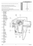
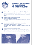
In fig.6 sono indicati gli usi relativi alle posizioni delle due manopole poste sulla pompa.
Azionare la leva per far discendere il pistone, eseguire il lavoro quindi riportare il pistone a riposo
azionando la manopola relativa (fig.6).
La leva di azionamento della pompa è libera così da poterla sfilare o spostare nel caso infastidisse le operazioni di lavoro sulla pressa.
·
·
·
·
MANUTENZIONE
· Oliare le parti in movimento della pressa ogni sei mesi e verificare il funzionamento del manome-
tro.
· L’unità idraulica (cilindro/pompa) è un sistema sigillato che in condizioni normali richiede solo
una lubrificazione semestrale dei pezzi mobili. Nel caso in cui l’unità idraulica perda olio e venga
smontata per la sostituzione delle guarnizioni, sarà necessario aggiungere olio attraverso il foro
di riempimento posto sulla pompa (rif.6, fig.7), fino a riempire la pompa a livello del foro stesso.
Questa operazione deve essere fatta con pistone a riposo pertanto completamente rientrato. L’olio nell’unità idraulica va comunque sostituito ogni due anni indipendentemente dalle condizioni generali dell’unità stessa.
Usare olio idraulico con viscosità da 22° a 25°.
Nella tabella a lato viene indicata la quantità di olio necessaria ad ogni tipo di pressa.
Una quantità maggiore d’olio potrebbe causare inconvenienti.
Modello
PR15B/PM
PR15/PM
Kg di olio
1,4
IATTENZIONE
Non usare MAI olio per freni.
INFORMAZIONI PARTICOLARI
· L’olio esausto prelevato dalla pressa deve essere smaltito secondo le leggi vigenti nel paese di
installazione della macchina.
· In caso di distruzione della pressa, tutte le parti metalliche sono riciclabili; i tubi in gomma e i fluidi
della pressa devono essere eliminati secondo le leggi vigenti nel paese di installazione della
pressa.
4
F
MANUEL D’UTILISATION ET D’ENTRETIEN pour les
PRESSES HYDRAULIQUES D’ATELIER
Mod. PR15B/PM - PR15/PM
RESPONSABILITE DU PROPRIETAIRE ET/OU DE L’UTILISATEUR DE LA PRESSE
Ce manuel fait partie intégrante de la presse et doit toujours l’accompagner, même en cas de
revente. Le propriétaire et/ou l’utilisateur de la presse doit connaître les instructions et les recommandations d’emploi avant de se servir de la presse, Si l’opérateur ne comprend pas la langue dans laquelle est rédigé ce manuel, les instructions devront lui être Iues et expliquées dans
sa langue maternelle en s’assurant que celles-ci soient bien comprises. Le constructeur décline toute responsabìlité relative aux dommages qui pourraient être causés aux personnes
et aux biens par suite d’une utilisation de la presse incorrecte et non appropriée.
EMBALLAGE
Les presses sont expédiées en un seul colis, protégées par un film plastique multi-bulles. Poids
des presses:
Mod.
PR15B/PM
PR15/PM
Kg.
135
140
MANUTENTION ET DEPLACEMENT
Les presses doivent toujours être déplacées et positionnées au moyens de chariots à fourches
ou de grues d’atelier pouvant en supporter le poids.
STOCKAGE
Les presses devront être conservées emballées dans des endroits couverts et protégés, à des
températures comprises entre -10°C et +40°C.
SECURITE
Ne pas utiliser la presse pour d’autres usages que ceux pour lesquels elle a été conçue.
Ne pas travailler sur les pièces à presser lorsque le piston est en mouvement ou sous pression.
La soupape de sécurité est tarée et plombée par le constructetur: NE PAS TENTER DE LA DEMONTER OU D’EN MODIFIER LE REGLAGE. Le NON-RESPECT de ces RECOMMANDATIONS peut causer les dommages, mêmes graves, à la personne et/ou personnes qui travaillent avec la presse.
LE CONSTRUCTEUR DECLINE TOUTE RESPONSABILITE RELATIVE AUX DOMMAGES
QUI POURRAIENT ÊTRE CAUSES AUX PERSONNES OU AUX BIENS PAR SUITE D’UNE
UTILISATION IMPROPRE DE LA PRESSE OU DE SES ACCESSOIRES.
MONTAGE
· Enlever la presse de son emballage multi-bulles en vérifiant qu’elle n’ait subit aucun dommage
en cours de transport et qu’il ne manque aucun des éléments mentìonnés sur le bordereau de
colisage. Les matériaux d’emballage devront être soit éliminés selon les normes en vigueur dans
le pays où la presse est installée, soit recyclés ou réutílisés.
· Positionner la presse sur un surface plane et horizontale. A l’intérieur des pieds sont pratiqués
deux trous permettant l’ancrage éventuel de la presse sur le sol au moyen de chevilles à expansion de dimension adéquate.
n Monter les pieds sur le bâti de la presse au moyen des boulons fournis (fig.1) et la fixer ensuite, à l’aide de boulons traversants, sur le plateau d’un établi suffisamment robuste pour en
supporter le poids.
5
· Enlver le bouchon au sommet du vérin, appliquer du Téflon sur le filetage du manomètre et visser
ce dernier sur le vérin en serrant à l’aide d’une clé jusqu’à blocage complet (fig.2).
INSTRUCTIONS D’EMPLOI
· Positionner la table de la presse (réf.1, fig.4) à la hauteur désirée, en soulevant d’abord une ex-
trémité et en insérant la broche (2) dans le trou du bâti immédiatement en dessous puis répéter
l’opération pour l’autre extrémité.
n Placer les boches (2) à la hauteur voulue.
IATTENTION
TOUTES LES OPERATIONS DE PRESSAGE DOIVENT ÊTRE EFFECTUEES AVEC LA
TABLE EN APPUI SUR LES BROCHES.
Positionner les vés (ref.3, fig.4) sur la table (1)
Introduire le levier de la pompe (4) dans son support (5) sur le haut de la pompe.
En Fig.6 sont indiquées les fonctions des deux robinets situés sur la pompe.
Actionner le levier plusieurs fois de haut en bas pour faire descendre le piston, actionner ensuite
le robinet situé sur la pompe (fig.6) pour obtenir le retour du piston à sa position initiale.
Le levier de la pompe est libre de façon à pouvoir s’enlever ou se déplacer dans le cas où il
gênerait les opérations de travail autour de la presse.
·
·
·
·
ENTRETIEN
· Huiler les parties en mouvement tous les six mois et contrôler le bon fonctionnement du ma-
nomètre.
· L’unité hydraulique (pompe/vérin) est un système fermé qui, en utilisation normale, ne demande
qu’une lubrification semestrielle des parties mobiles. Dans le cas ou l’unité hydraulique présenterait une fuite d’huile et serait démontée pour remplacement des joints, il sera nécessaire de refaire le plein d’huille au travers de l’orifice de remplissage situé sur la pompe (réf.6, fig.7) jusqu’à ce
que le niveau de l’huile atteigne le bord de l’orifice. Cette opération doit être faite avec le piston
du vérin en position de repos, c’est à dire complètement rentré. L’huile de l’unité hydraulique doit, de toutes façons, être remplacée tous les deux ans, quel que soit l’état de l’unité
hydraulique.
Utiliser de l’huile hydraulique de viscosité 22°E à 25°E
Le tableau ci-contre indique la quantité d’huile nécessaire pour chaque modèle de presse.
Une quantité supérieure peut nuire au bon fonctionnement de
la presse.
IATTENTION
Modèle
PR15B/PM
PR15/PM
Kg huile
1,4
Ne JAMAIS utiliser du liquide de freins!
INFORMATIONS PARTICULIERES
· L’huile usagée provenant de la presse doit être éliminée en conformìté avec les normes en vi-
gueur dans le pays où est installée la presse.
· En cas de destruction de la presse, toutes les parties métalliques sont recyclables, le canalisations en caoutchouc et les fluides contenus dans la presse devront être éliminés en conformité
avec les normes en vigueur dans le pays où est installée la presse.
6
GB
MAINTENANCE MANUAL for WORKSHOP HYDRAULIC
PRESSES
Mod. PR15B/PM - PR15/PM
1) LIABILITY OF PRESS OWNER AND/OR USER
This manual is an integral part of the press and must always accompany it, even in the event of
sale. The press owner and/or user must know the operating instructions and recommendations
before using the press. If the operator does not fully understand the language of this manual,
the instructions have to be read and explained in his or her native language making sure the
meaning is understood. The manufacturer shall not be held liable for any damage to persons or objects due to an improper or non-permitted use of the press.
PACKING
The press is shipped in a single pack protected by pluriball plastic material.
Weights of presses:
Mod.
PR15B/PM
PR15/PM
Kg.
135
140
LIFTING AND HANDLING
The presses have to be handled and positioned using fork-lift trucks or workshop cranes that
support the weight.
STORAGE
The packing has to be kept in a covered and sheltered place at a temperature between -10°C
and +40°C.
SAFETY
Do not use the press for purposes other than those for which it was designed.
Do not work alongside pieces while the ram is moving or when it is under pressure.
The safety valve is calibrated and sealed by the manufacturer: DO NOT ATTEMPT TO TAMPER WITH IT AND CHANGE THE SETTING.
FAILURE to OBSERVE these RECOMMENDATIONS may cause even serious damage to the
press and/or to the persons working with it.
THE MANUFACTURER SHALL NOT BE HELD LIABLE FOR DAMAGE TO PERSONS OR
THINGS CAUSED BY IMPROPER USE OF THE PRESS OR OF ITS COMPONENTS.
ERECTION
· Take the press out of it pluriball wrapping, checking that the machine has not been damaged during transport and that there are all the pieces indicated in the packing list. The packing material
has to be disposed of in compliance with the regulations in force in the country where the press is
being erected or recycled or reused.
· Position the press on a flat and fully levelled surface. Inside the feet there are two holes for fixing
to the ground by using expansion plugs of a large cross-section.
n Fit the feet to the body of the press by screwing them on with the nuts and bolts supplied (Fig.
1). Then fix the press to a solid bench of a suitable capacity load (see press weights), locking
it by means of through bolts and nuts to the workbench.
· Remove the cap on the top of the ram, seal the thread of the pressure gauge with Teflon and
screw the pressure gauge onto the ram, tightening it with a spanner until it is fully locked (Fig. 2).
7
OPERATING INSTRUCTIONS
· Position the bed of the press (ref. 1, Fig. 4) at the desired height, lifting it first on one side and in-
serting one of the pins (2) into the hole in the press body directly beneath, then repeating this step
for the other side as well.
n Position the pins (2) at the desired point.
I WARNING
ALL WORK OPERATIONS ARE TO BE MADE WITH THE BED RESTING ON THE PINS.
Position the prisms (ref. 3, Fig. 4) on the bed (1).
Insert the lever of the pump (4) into its relative seat (5) on the pump.
Fig. 6 shows the uses relative to the positions of the two dials on the pump.
Operate the lever to lower the ram, carry out the work then bring the ram back to rest with the relative dial (Fig. 6).
The pump operating lever is thereby free to be able to be extracted or moved if it gets in the way
of work on the press.
·
·
·
·
MAINTENANCE
· Oil the moving parts of the press every six months and check operation of the pressure gauge.
· The hydraulic unit (cylinder/pump) is a sealed system that in normal conditions requires only six-
monthly lubrication of the moving parts. In the event of the hydraulic unit leaking oil and being dismantled in order to replace the seals, it will be necessary to add oil through the filler hole on the
pump (ref. 6, Fig. 7) until the pump has been filled up to the level of the hole itself. This operation
has to be done with the ram at rest and therefore fully retracted. The oil in the hydraulic units
should anyhow be replaced every two years independently of the general conditions of the unit.
Use hydraulic oil with viscosity from 22° to 25°.
The table shown here gives the quantity of oil needed for each type of press.
A greater amount of oil could cause trouble.
IWARNING
Model
PR15B/PM
PR15/PM
Kg of oil
1,4
NEVER use brake oil.
SPECIAL INFORMATION
· The waste oil taken from the press has to be disposed of in compliance with the laws in force in
the country where the machine is installed.
· If the press is to be destroyed, all the metal parts can be recycled; the rubber hoses and the press
fluids have to be disposed of in compliance with the laws in force in the country where the machine is installed.
8
D
WARTUNGSANLEITUNG FUER HYDRAULISCHE
WERKSTATTPRESSEN
Mod. PR15B/PM - PR15/PM
VERANTWORTLICHKEIT DES EIGENTUEMERS UND / ODER DES ANWENDERS VON
PRESSEN
Diese Anleitung muss dem Artikel immer beigelegt sein, auch bei Verkauf. Der Eigentuemer/Anwender muss sich vor Inbetriebnahme der Presse mit der Gebrauchsanweisung vertraut
machen und die Hinweise beachten. Wenn der Anwender die Anleitung in der jeweils geschriebenen Sprache nicht versteht, muss diese ihm in seiner Sprache erklaert werden, so dass der
Sinn verstanden wird. Der Hersteller haftet fuer keine Personen- und Sachschaeden bei
nicht sachgemaesser Handhabung.
VERPACKUNG
Die Presse wird als ein Kolli verschickt und in gepolsterte Plastikfolie verpackt.
Gewicht der Pressen:
Mod.
PR15B/PM
PR15/PM
Kg.
135
140
HEBEN UND BEWEGUNG
Die Pressen muessen mit einem Gabelstabler oder Werkstattkran bewegt und positioniert werden, die das Gewicht aushalten.
LAGERUNG
Die Verpackungen muessen in geschuetzten Raeumen, bei Temperaturen zwischen -10° und
+40°C. gelagert werden
SICHERHEIT
Die Pressen nur fuer den ihr vorgesehenen Zweck verwenden.
Nicht nebenbei an Teilen arbeiten, wenn der Kolben in Bewegung ist, oder unter Druck steht.
Das Sicherheitsventil ist vom Hersteller eingestellt: NIEMALS VERSUCHEN, DASS VENTIL ZU
VERSTELLEN.
DAS NICHTEINHALTEN dieser HINWEISE kann grosse Schaeden an der Presse oder an Personen verursachen.
DER HERSTELLER HAFTET FUER KEINERLEI PERSONEN - UND SACHSCHAEDEN BEI
UNSACHGEMAESSER HANDHABUNG
MONTAGE
· Die Presse vom Plastik befreien und ueberpruefen, ob die Presse Transportschaeden aufweist
oder Teile fehlen. Das Verpackungsmaterial muss gemaess der landesueblichen Umweltgesetze entsorgt werden.
· Die Presse auf einen ebenen Boden stellen. Im Innern des Fusses finden sich zwei Loecher, die
zur Befestigung mit Duebeln in den Boden dienen.
n Die Fuesse an den Pressenkoerper mit den beigefuegten Schrauben und Muttern (Fig.1)
anbringen.Dann die Presse an eine ebene Ablage anbringen, die eine geeignete Tragkraft
(siehe Pressengewichte) aufweist, diese mit Bolzen und Muttern an der Arbeitsablage festmachen.
· Den Propfen von der Kolbenkrone entfernen, das Gewinde des Manometers mit Teflon versiegeln und das Manometer an den Kolben anbringen, dieses mit einem Schluessel festziehen, bis
es ganz festsitzt. (Abb.2)
9
GEBRAUCHSANWEISUNG
· Das Bett der Presse (ref.1, Abb.4) auf die gewuenschte Hoehe bringen, dabei erst eine Seite he-
ben und einen der Stifte (2) in das Loch des Pressenkoerpers, dass sich darunter befindet, einfuehren. Dann diesen Vorgang mit der anderen Seite durchfuehren.
n Die Stifte (2) in dem gewuenschten Punkt anbringen.
IACHTUNG
ALLE ARBEITSSCHRITTE SIND SO DURCHZUFUEHREN, DASS DAS BETT AN DEN
STIFTEN ANGELEHNT IST.
· Die Prismen auf dem Bett (1) positionieren (Ref.3, Abb.4)
· Den Hebel der Pumpe (4) in den dafuer vorgesehenen Sitz einfuehren (5)
· In Abb.6 sind die jeweiligen Anwendungen, wie die zwei Griffe an der Pumpe angebracht wer-
den, aufgefuehrt.
· Den Hebel betaetigen, um den Kolben herunter zu fahren, die Arbeit durchfuehren und dann den
Kolben wieder in die Ruhestellung bringen, indem der jeweilige Drehknopf betaetigt wird (Abb.6)
Der Betaetigungshebel der Pumpe ist frei, dadurch kann er herausgenommen oder verrueckt
werden, sofern er die Arbeitsschritte an der Presse behindert.
WARTUNG
· Die sich bewegenden Teile alle sechs Monate oelen und ueberpruefen, ob das Manometer funk-
tioniert.
· Die Hydraulikeinheit (Zylinder/Pumpe) ist ein versiegeltes System. Im Normalfall muessen die
beweglichen Teile alle sechs Monate geschmiert werden. Sollte die Hydraulikeinheit Oel verlieren und die Dichtungen dieser ausgetauscht werden sollen, ist es notwendig, Oel durch das Auffuelloch ,das auf der Pumpe (Ref 6, Abb 7) sitzt, hinzuzufuegen. Dieses muss ganz gefuellt sein.
Diesen Vorgang nur mit Kolben in Ruheposition, also wenn er ganz eingefahren ist, durchfuehren. Das Oel in der Hydraulikeinheit alle zwei Jahre, unabhaengig vom Zustand der Einheit, austauschen.
Oel mit einer Viskositaet von 22° bis 25° verwenden
In der nebenstehenden Tabelle wird die noetige Oelmenge fuer jeden Pressentyp angegeben.
Eine erhoehte Oelmenge kann Stoerungen verursachen.
IACHTUNG
Modell
PR15B/PM
PR15/PM
Oel Kg
1,4
Niemals Bremsoel verwenden
BESONDERE INFORMATIONEN
· Das Altoel der Pressen muss gemaess der landesueblichen Umweltgesetze entsorgt werden.
· Sollte die Presse vernichtet werden: Alle Metallteile sind wiederverwertbar; die Gummischlaeu-
che und die Fluessigkeiten der Presse muessen gemaess der landesueblichen Gesetze entsorgt
werden.
10
15 t B PM
15 t PM
R0082
R0265
Part
Code
Descrizione
Description
Beschreibung
Description
Denominacion
A0315
A0346
B0080
B5005
C0062
C0519
R0046
R0058
R0071
R0076
R0082
R0093
R0098XX
R0100
R0120
DADO ALTO M12 ZB UNI 5587
RONDELLA P 12 X 24 UNI 6592
DADO M10 UNI 5589
VITE TE M10X25 UNI 5739
RONDELLA Ø10,5X21 UNI 6592
RACCORDO “L” M 3/8"
DADO MEDIO M12 UNI 5588
MANOMETRO Ø 63 MM.
SUPPORTO V
PIANO DI LAVORO
POMPA A MANO
SPINA D 25X320
TELAIO PR15T COLONNA CIL.MOBIL
CORPO POMPA A MANO SERIE
VOLANTINO 6 LOBI MA8X50 SERIE
GALVANIZED NUT M12
WASHER 12 X 24
NUT M10 UNI 5589
SCREW TE M10 X 25
WASHER Ø10,5X21
“L” CONNECTION M/M 3/8"
NUT M12
MANOMETER Ø 63 MM.
“V” SUPPORT
WORKING PLANE
PUMP COMPLETE
PLUG Ø 25 X 320 MM.
FRAME
HAND PUMP BODY
HANDWHEEL
ECROU HAUT M12
RONDELLE Ø13X24
ECROU M10 UNI 5589
VIS TH M10 X 25
RONDELLE Ø10,5X21
COUDE EN “L” M/M 3/8"
ECROU M12
MANOMÈTRE Ø 63 MM.
SUPPORT EN “V”
TABLE DE TRAVAIL
POMPE COMPLETE
GOUPILLE Ø 25 X 320 MM.
CHASSIS
CORPS DE POMPE MAN.
MOLETTE
TUERCA ALTA M12
ARANDELA 13X24
TUERCA BAJA M10 ZINCADA
TORNILLO TE M10X25
ARANDELA PLANA Ø10 5X21
CONEXION “L” M 3/8"
TUERCA M12
MANÓMETRO
SOPORTE
R0121
TAPPO 1/2"+RONDELLA ALL. 1/2"
CAP AVP 1/2" + WASHER ALUMINUM
R0132
R0140
R0173
R0174
R0175
R0188
R0206
R0207
R0208
R0209
R0251XX
R0263XX
R0265
R0266
R0267
R0268
R0467
R0468
R0469
R0470
R0471
R0474
R0478
R0666
RONDELLA RAME 3/8"
VITE TE M12X90 UNI 5737 ZB
SEEGER E50 UNI 7435
KIT GUARNIZIONI
MOLLA PISTONE
LEVA COMANDO POMPA A MANO
PISTONE
BUSSOLA GUIDA CILINDRO
TESTATA PISTONE
TAPPO+GRANO 8X10
PIEDE
TELAIO
CILINDRO COMPL. BANCO
DISTANZ.SCORREVOLE
CANNA CILINDRO
TUBO MANDATA OLIO
KIT VARIATORE POMPA A MANO
KIT VALVOLA DI SCARICO
KIT VALV. ASP.-COMP. ALTA PRES
KIT VALVOLA DI MASSIMA POMPA
KIT VALV. ASP.-COMP. BASSA PRE
KIT BIELLA POMPA
ATTACCO LEVA COMANDO POMPA A
MANO
KIT POMPANTE POMPA
VITE TE M12X35 UNI 5739 ZB
WASHER 3/8" UNI 7989
SCREW TE M12 X 90 UNI 5737
SEEGER E50 UNI 7435
GASKETS KIT
SPRING FOR PISTON
HAND PUMP CONTROL LEVER
PISTON
BUSH CYLINDER GUIDE
PISTON HEAD
PLUG + GRAB SCREW (8X10 UNI 5923)
FOOT
FRAME
CYLINDER COMPLETE
SPACER
CYLINDER TUBE
OIL DELIVERY HOSE
SPEED VARIATOR KIT
EXHAUST VALVE KIT
HIGH PRESSURE VALVE KIT
SAFETY VALVE KIT
LOW PRESSURE VALVE KIT
CONNECTING MOD KIT
HAND PUMP CONTROL LEVER
CONNECTION
PUMPING ELEMENT
SCREW M12X35 UNI 5739 ZB
MUTTER M12
UNTERLEGSCHEIBE 12 X 24
MUTTER M10 UNI 5589
SCHRAUBE TE M10 X 25
SCHEIBE Ø10,5X21
“L”-ANSCHLUSS M/M 3/8"
MUTTER M12
MANOMETER Ø 63 MM.
HALTERUNG A “V”
ARBEITSPLATTE
PUMPE KOMPLETT
STIFT Ø 25 X 320 MM.
GESTELL
HANDPUMPENKOERPER
DREHKNOPF
PFROPFEN AVP 1/2" +
UNTERLEGSCHEIBE
KUPFERSCHEIBE 3/8“
SCHRAUBE TE M12 X 90 UNI 5737
SEEGER-RING E50 UNI 7435
SET DICHTUNG
FEDER FUER KOLBEN
HANDPUMPENKOMMANDOHEBEL
KOLBEN
FUEHRUNGSBUCHSE ZYLINDER
KOLBENKOPF
PFROPFEN + DUEBEL (8X10 UNI 5923)
FUSS
GESTELL
ZYLINDER KOMPLETT
DISTANZSTÜCK
ZYLINDERROHR
SCHLAUCH
SET GESCHWINDIGKEITSREGLER
SET ABLASSVENTIL
SET HOCHDRUCKVENTOLE
SET UEBERDRUCKVENTIL
SET UNTERDRUCKVENTIL
SET FLANSCH
VERBINDUNGSSTÜCK
HANDPUMPENKOMMANDOHEBEL
SET PUMPENELEMENTE
SCHRAUBE M12X35 UNI 5739 ZB
Z_ZCONS
* = RICAMBI CONSIGLIATI
* = RECOMMENDED SPARE PARTS
* = EMPFOHLENE E-TEILE
R0477
Sugg
BOMBA
ESTRUCTURA
CUERPO BOMBA
VOLANTE
BOUCHON AVP 1/2" + RONDELLE ALL.
RONDELLE 3/8" UNI 7989
VIS TH M12 X 90 UNI 5737
CIRCLIPS E50 UNI 7435
KIT DE JOINTS
RESSORT DE PISTON
LEVIER DE COMMANDE P.M.
PISTON
BAGUE-GUIDE PISTON
EMBOUT DE VÉRIN
BOUCHON + VIS (8X10 UNI 5923)
PIED
CHASSIS
VÉRIN COMPLET
ENTRETOISE
CYLINDRE DE VÉRIN
TUBE DE REFOULEMENT D’HUILE
ENSEMBLE CHANGEUR DE VITESSE
ENSEMBLE VALE DE DECHARGE
ENSEMBLE VALVE ASP./REF. H.P.
ENSEMBLE VALVE DE SURPRESSION
ENSEMBLE VALVE ASP./REF. B.P.
ENSEMBLE FLASQUE
FIXATION LEVIER DE COMMANDE
P.M.
ENSEMBLE PISTON
VIS M12X35 UNI 5739 ZB
* = PIECES DE RECHANGE
CONSEILLEES
ARANDELA DE COBRE 3/8"
TORNILLO
SEEGER
JUEGO DE JUNTAS
PALANCA
PISTÓN
CASQUILLO
TAPA + TORNILLO
PIE
BASTIDOR
CILINDRO
DISTANCIADOR
CAÑA CILINDRO
TUBO
TORNILLO M12X35 UNI 5739 ZB
* = REPUESTOS ACONSEJAIOS
Dichiarazione di conformità - Declaration of Conformity
Konformitätserklärung - Déclaration de conformité
Declaración de conformidad - Overensstemmelseserklæring
Samsverserklæring - Överensstämmande intyg
EG-Conformiteitsverklaring
WERTHER INTERNATIONAL S.p.A.
Via F.Brunelleschi, 12 42040 CADE’ (Reggio Emilia) Italy
Tel.++/+522/9431 (r.a.) Fax ++/+522/941997
con la presente dichiara che - hereby declare that
déclare par la presente que - erklären hiermit, daß
por la presente declara, que - com a presente declaramos que a
verklaart hiermee, dat - Vi erklærer hermed, at autoløfter model
Vi erklærer herved, at løftebuk model - Vi förklarer härmed att billyft model
Presse idrauliche modelli - Presse hydraulique modèle
Hydraulic presses model - Hydraulischen pressen modell
Prensas hidráulicas - Prensa modelo
De hydraulische werkplaatspers model - Hydraulske presser modell
Hydrauliska pressar, modeller - Hydrauliske presser
PR15B/PM - PR15/PM
I
è stato costruito in conformità alle normative
73/23 CEE - 89/336 CEE e 98/37/CE
was manufactured in conformity with the normes
73/23 CEE - 89/336 CEE and 98/37/CE
F
a été construite en conformité avec les normes
73/23 CEE - 89/336 CEE et 98/37/CE
in Übereinstimmung mit den Richtlinien 73/23 CEE
89/336 CEE und 98/37/CE
GB
D
E
ha sido fabricado según las disposiciones 73/23
CEE - 89/336 CEE y 98/37/CE
fue produzida em conformidade com a
norma 98/37/CE
P
waarop deze verklaring betrekking heeft, voldoet
ble produsert i samsvar med direktivene 73/23
CEE - 89/336 CEE - 98/37/CE
N
de voorschriften van richtlijn 73/23/EEG en
NL aan
89/336 EEG en 98/37 EEG en de daaropvolgende
veranderingen en aanvullingen.
S
är framställt i överensstämelse med bestämelser I
RÅDETS DIREKTIV 73/23 EG - 89/336 EG 98/37/EG
Cadè, 08/03/2002
p.i. Werter Iori
er fremstillet i overensstemmelse med
bestemmelserne i 73/23 EØF - 89/336 EØF 98/37/EØF
DK