1
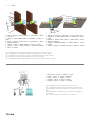
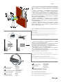
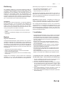
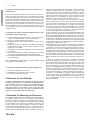
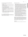
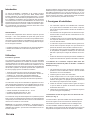
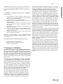
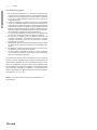
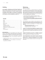
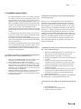
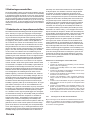
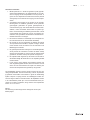
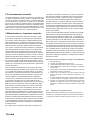
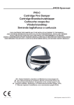
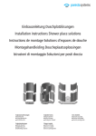
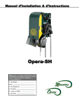
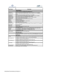
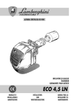
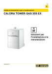
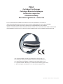
PKI-C
Cartridge Fire Damper
Cartridge-Brandschutzklappe
Cartouche coupe-feu
Vlinderbrandklep
Serranda tagliafuoco a cartuccia
EACH CARTRIDGE FIRE DAMPER HAS TO BE INSTALLED ACCORDING TO THIS MANUAL!
JEDE CARTRIDGE-BRANDSCHUTZKLAPPE SOLLTE NACH DIESEM MANUAL INSTALLIERT WERDEN!
TOUTE CARTOUCHE COUPE-FEU DOIT ETRE INSTALLEE CONFORMEMENT A CE MANUEL!
IEDERE VLINDERBRANDKLEP MOET WORDEN GEÏNSTALLEERD ZOALS OMSCHREVEN IN DEZE HANDLEIDING!
OGNI SERRANDA TAGLIAFUOCO A CARTUCCIA DEVE ESSERE INSTALLATA SECONDO QUESTO MANUALE!
1396 - CPD - 0050
GB - Original Installation, Operation and Maintenance manual (page 4-7)
DE - Die original Anleitung für Installation, Betrieb und Kontrolle (Seite 8-11)
FR - Manuel original d´installation, d´utilisation et de contrôle (pages 12-15)
NL - Originele Installatie-, Bedienings- en Onderhoudsvoorschriften (pagina 16-19)
IT - Manuale originale di installazione, uso e manutenzione (pagina 20-23)
Systemair March 2013 PP74_PKI-C
2/8
|
PKI-C
1
1
2
2
3
4
3
4
d
5
m
d+60 m
d
m
d+60 m
5
1 - Wall, 2 - Gypsum / mortar/ concrete, 3 - Steel duct, 4 - PKI-C,
5 - Disc valve
1 - Decke, 2 - Gips / Mörtel / Beton, 3 - Stahlrohr, 4 - PKI-C, 5 Ventil
1 - Paroi, 2 - Plâtre / mortier / béton, 3 - Gaine acier, 4 - PKI-C,
5 - Bouche coupe-feu
1 - Plafond, 2 - Gips, 3 - Stalen kanaal, 4 - PKI-C, 5 - Ventiel
1 - parete, 2 - gesso / malta / cemento, 3 - condotto in acciaio,
4 - PKI-C, 5 - valvola
1 - Ceiling, 2 - Gypsum, 3 - Steel duct, 4 - PKI-C, 5 - Disc valve
1 - Die Mauer, 2 - Gips / Mörtel / Beton, 3 - Stahlrohr, 4 - PKI-C,
5 - Ventil
1 - Plafond, 2 - Plâtre / mortier / béton, 3 - Gaine acier, 4 - PKI-C,
5 - Bouche coupe-feu
1 - Wand, 2 - Gips/specie/beton, 3 - Stalen kanaal, 4 - PKI-C,
5 - Ventiel
1 - soffitto, 2 - gesso, 3 - condotto in acciaio, 4 - PKI-C, 5 - valvola
Fig. 1 Embedding of the cartridge fire damper using gypsum / mortar / concrete
Abb. 1 Installation einer Cartridge-Brandschutzklappe mit Gips / Mörtel / Beton
Fig.1. Installation d’une cartouche coupe-feu en utilisant du plâtre / mortier / béton
Fig. 1 Afwerking van de vlinderbrandklep met gips, specie of beton
Fig. 1 Inserimento della serranda tagliafuoco a cartuccia con gesso / malta / cemento
1 - Disc valve, 2 - PKI-C, 3 - Gypsum, 4 - Duct
1 - Ventil, 2 - PKI-C, 3 - Gips, 4 - Rohrleitung
1 - Valve, 2 - PKI-C, 3 - Gypse, 4 - Tube
1 - Ventiel, 2 - PKI-C, 3 - Gips, 4 – Kanaal
1 - valvola, 2 - PKI-C, 3 - gesso, 4 - condotto
1
2
3
4
Fig. 2 Installation Into the End of a Duct with a Valve
Abb. 2 Installieren Sie das Ende des Rohres mit einem Ventil
Fig.2 Installation au bout de la gaine avec une bouche de ventilation
Fig. 2 Installatie in het uiteinde van een kanaal met behulp van
een ventiel
Fig. 2 Installazione a fine condotto con una valvola
PKI-C
|
3/8
1 - PKI-C, 2 - Cover plates, 3 - Mineral wool with a minimum density of 50- 100 kg.m-3, 4 - Steel duct, 5 - Disk valve, 6 - Plasterboard
wall, 7 - Mineral wool, 8 - Horizontal profile UW, 9 - Vertical profile
CW
1 - PKI-C, 2 - Deckplatten, 3 - Mineralwolle mit min. Dichte von
50 bis 100 kg/m3, 4 - Stahlrohr, 5 - Ventil, 6 - Gipskartonwände,
7 - Mineralwolle, 8 - Horizontal Profil UW, 9 - Vertikal-Profil CW
1 - PKI-C, 2 - Plaques de couverture, 3 - Laine minérale de densité
minimale de 50 à 100 kg.m3, 4 - Gaine acier, 5 - Bouche coupefeu, 6 - Cloison en placoplâtre, 7 - Laine minérale, 8 - Profilé horizontal UW, 9 - Profilé vertical CW
1 - PKI-C, 2 - Afdekplaten, 3 - Minerale wol met een minimale
dichtheid van 50 - 100 kg.m-3, 4 - Stalen kanaal, 5 - Ventiel, 6 Wand van gipsplaat, 7 - Minerale wol, 8 - Horizontaal profiel UW,
9 - Verticaal profiel CW
1 - PKI-C, 2 - lastre di copertura, 3 - lana minerale con densità
minima di 50 - 100 kg.m-3, 4 - condotto in acciaio, 5 - valvola, 6 parete in cartongesso, 7 - lana minerale, 8 - profilato orizzontale
UW, 9 - profilato verticale CW
1
2
Fig. 3 Embedding of the cartridge fire damper using mineral wool
Abb. 3 Installation von der Cartridge-Brandschutzklappe mit
Mineralwolle
Fig.3 Installation d’une cartouche coupe-feu en utilisant de la
laine minérale
Fig. 3 Inbedden van de vlinderbrandklep met minerale wol
Fig. 3 Inserimento della serranda tagliafuoco a cartuccia in una
parete in cartongesso con lana minerale
1 - Press both detent springs, 2 - Open the blades into a parallel
position, 3 - Put on the thermal fuse link
1 - Drücken die beiden Arretierfedern, 2 - Öffnen Briefe an die parallele Position, Dritte Ersetzen Sie die Thermosicherung
1. Poussez les deux ressorts à lames, 2. Mettez les lames en position horizontale, 3. Cliquez le fusible thermique
1 - Druk beide palveren in, 2 - Open de bladen in een parallel positie, 3 - Plaats de thermische smeltlood
1 - sbloccare entrambe le molle di arresto, 2 - aprire le alette in
posizione parallela, 3 - inserire il fusibile
3
Fig. 4 Adjusting the Damper into Operating Position
Abb. 4 Stellung der Cartridge-Brandschutzklappe in die geöffnete
Position
Fig.4 Réarmement de la cartouche coupe-feu
Fig. 4 Instellen van de brandklep in de definitieve positie
Fig. 4 Regolazione della serranda in posizione di funzionamento
1
2
3
1 2 CLOSED indicator 3 OPEN indicator
- black wire
- blue wire
- grey wire
1 - schwarzer Kabel
2 Anzeige GESCHLOSSEN - blauer Kabel
3 Anzeige GEÖFFNET
- grauer Kabel
1 2 Indication FERMÉ 3 Indication OUVERT - fil noir
- fil bleu
- fil gris
1 2 GESLOTEN indicator
3 OPEN indicator
- zwarte draad
- blauwe draad
- grijze draad
1 - terra filo nero
2 segnalazione di chiusura- filo blu
3 segnalazione di apertura- filo grigio
Fig. 5 Connection of the end switch
Abb. 5 Beteiligung der Endschalter
Fig. 5 Branchement d’un interrupteur fin de course
Fig. 5 Aansluiten van de eindschakelaar
Fig. 5 Collegamento del finecorsa
4/8
|
PKI-C
GB
Introduction
The Installation, Operation and Maintenance manual applies
to the cartridge fire damper types PKI-C E60S, EI60S, EI90S,
EI120S, produced by IMOS-Systemair, contains basic information and recommendations regarding the design, installation and
usage, which need to be followed in order to guarantee a proper
and trouble-free operation of the unit. The key to this is to read this
manual thoroughly, use the damper according to the instructions
provided in it and to adhere to the safety requirements.
Warning
Some of the fire damper parts might have sharp edges – therefore it is necessary to use gloves during the installation and usage
of the damper.
In order to avoid electrical shock, fire or other damage that might
occur as a result of incorrect usage and operation of the unit, it is
important to comply with the following principles:
• It is necessary to install the system according to the Installation
manual.
• It is necessary to perform the fire damper check according to
the manual.
Operation
General Information
The IMOS – Systemair cartridge fire dampers are defined as fire
closures for ventilation ducts, to be installed in the spot where
the ventilation duct passes through the fire partition wall, or at the
end of the duct in front of the outlet. In case of a fire the dampers
work as a fire safety element and prevent the fire from spreading
throughout the ventilation duct during a specified amount of time.
• All the units are actuated by springs.
• Additional accessories, such as flexible couplings, disk valves
etc., can be ordered separately.
• The accessories are supplied separately and unmounted, ready to be mounted on site by the responsible staff.
The dampers are to be operated in a workplace which is protected
from weather conditions and to be used in ventilation ducts distributing the air without any other mechanical or chemical contamination in the following operating conditions:
• The maximum air flow speed of 12m/s
• The maximum relative air humidity of 90%
• The temperature falling within the range of -10 to +65°C
In terms of noise, the IMOS – Systemair fire dampers are passive.
Increased noisiness only occurs while the damper is being opened
or closed as a result of inspection or fire, which should not last
longer than 5 seconds.
Note: The accessories for mounting – cover plates for dry installation and a flexible coupling for inspection simplification – can be
ordered along with the fire dampers.
As a standard, all the cartridge fire dampers are equipped with
a thermal fuse link, which, after having reached or exceeded
the temperature of 72 °C with a ± 1,5 °C tolerance, unblocks the
actuating springs, which causes the damper blades to close. Upon
request it is possible to supply thermal fuse links with a higher
fusion temperature.
1 Installation Manual
• The cartridge fire dampers are installed into the duct, either in
the place where the fire-proof wall is, or at the end of the duct
in front of an air valve or a similar outlet. (The cartridge fire
dampers are installed into the duct, either in the place where
the fire-proof wall is into a transversal duct, or at the end of the
duct in front of an air valve or a similar outlet.)
• The pitch between the ducts and the fire dampers must be at
least 200 mm, according to the STN EN 1366-2 regulation.
• According to the STN EN 1366-2 regulation, there must be at
least a 75 mm gap between the wall and the ductwork with the
fire damper.
• The fire damper is embedded into the fire partition construction
into duct in such a way that when the damper blades are in the
CLOSED position, thay will be entirely situated inside the wall.
• The damper can be embedded into a wall or a ceiling with a
minimum thickness according to the STN EN 1366-2 regulation
for the respective fire resistance class.
• All the dampers can be installed with a horizontal or a vertical
blade axis.
1.1 Embedding the PKI-C into a Wall / Ceiling Using Gypsum,
Mortar or Concrete – Wet Installation (see Fig. 1)
1. F
or installation purposes, make a round opening with a minimum diameter of Ød + 60 mm into the wall.
2. Insert the duct inside the middle of the opening.
3. Fill in the space between the wall and the duct with gypsum,
mortar or concrete, while paying special attention to not contaminate the inside of the duct. Plaster leakage can be prevented by using the cover plates.
4. Insert the fire damper into the duct and ensure that the whole
blade of the closed damper is situated within the wall.
5. Check the damper’s functionality (see the Operation manual).
1.2 Installation Into the End of a Duct with a Valve (see Fig.
2)
PKI-C can be installed into a wall/ceiling at the end of a duct with a
disc valve (the valve needs to be separately ordered from the ADP
catalogue – an advisable type would be the plastic valve „BalanceE“ from Systemair AB, Sweden). The installation is the same as
described in section 1.1, remembering that the end of the duct
must stay in allignment with the side of the wall/ceiling where the
valve is going to come. By installation PKI-C must be placed with
surface which contacts the closed blades in distance 50±10 mm
from end of the duct. The blades must be open in the direction into
the duct.
1.3 Embedding the PK-I into a Wall Using Mineral Wool – Dry
Installation (see Fig. 3)
1. F
or installation purposes, make a round opening with a minimum diameter of Ød + 60 mm into the wall.
2. Insert the duct inside the middle of the opening.
3. Attach the cover plates to the wall around one side of the duct.
4. Fill in the space between the wall and the duct with mineral
PKI-C
1.4 Adjusting the Damper into Operating
Position (see Fig. 4)
1. Press both detent springs
2. Open the blades into a parallel position
3. Put on the thermal fuse link
2 Operation Manual
The cartridge fire damper is ready for use when its blades are
open according to chapter 1.3 Adjusting the Damper into Operating Position. The blade position , if using a DV1 version, is indicated by an end switch, which indicates the damper blades’ open
and closed position.
The microswitch contains three isolated wires (see Fig. 5) which
need to be led out of the duct through a hole drilled in the duct as
close to the microswitch as possible and near the wall, the hole
being secured with a rubber grommet.
3 Maintenance and Inspection Manual
The actuating mechanism keeps the dampers on stand-by mode
throughout their entire operational life. Without the producer’s permission, there must be no changes or modifications performed
on the dampers’ structure. The operator executes regular damper
checks according to the local laws and regulations. Unless stated
otherwise, the operator checks the damper every 12 months. The
check must be performed by an employee who has been trained
for this duty. The fire damper condition determined by this check
is indicated in an operation journal (which is on page 7 of this
manual), along with the date of the check, a legible name and a
signature of the employee who had performed the check. A copy
of the employee’s authorization must be attached to the journal. If
any discrepancies are found, it is needed to enter the details about
them in the operation journal along with a proposal for their elimination and a date of the following revision. PKI-C is checked visually after having removed the disc valve from the duct end. If the
damper is installed in a duct crossing a fire-proof wall, to access
the damper it is needed to disjoin the duct pipe near the wall, on
the side where the damper blades open. For this purpose it is convenient to use a flexible coupling during installation – option „PS“,
according to the ordering code - which facilitates access inside the
damper. It is needed to check the damper’s internal casing, the
thermal fuse link, the sealing, the foaming substance, the damper
blade’s condition and its closure while it leans to a backstop in a
closed position. There must be no other objects or dirt from the
ventilation duct inside the damper. While performing the check,
also focus on the thermal fuse link’s integrity and a correct position
of the damper blades after their detention in the OPEN position –
they should be roughly parallel to the longitudinal axis of the duct.
Perform the damper activity check by taking off the thermal fuse
link and releasing the blades to spontaneously close them – the
damper blades are closed by a spring return release. The damper
must be completely closed – the blades must fall behind the detent
springs. If using the DV1 version, the blade’s position is indicated
5/8
by a connection of the respective circuit shown on Fig. 3.
After having checked that the sealing is intact and abuts against
the whole perimeter of the blade to the damper body, open the
blades again and detent them in the OPEN position using the thermal fuse link. When opening the blades it is first needed to push
the detent spring and use the hook attached to the opening of the
thermal fuse link’s holder to open the blade. Before opening the
second blade it is possible to secure the first blade in the OPEN
position by inserting an appropriate object between the blade and
the damper body (this object must be removed after the thermal
fuse link is put on.
In case of poor access when checking the damper functionality
by a complete closure of the blades (the damper is too small, the
duct pipe in the wall is too long...) it is possible to remove the damper from the duct. Do so by either pulling it out of the duct while
holding it by its open blades, or it is needed to disjoin the pipe on
the other side of the wall as well and push the damper out of the
duct. If using an end switch signalising the damper blades’ closed
position, it is necessary to disconnect the switch wires from the
terminal outside of the duct and pull the wires into the duct before
detaching the damper itself. After doing this, it is possible to take
the damper out of the duct. When remounting the damper into the
duct it is also essential to check the flexibility of the sealing on
the perimeter and in case it shows permanent deformation, it is
needed to replace the seal with a new one in order to guarantee a
correct fixation of the damper in the duct.
Recommended Check Steps According to the EN 15 650
Regulation
1.
2.
3.
4.
5.
6.
7.
8.
date of inspection
check of the end switch’s connection for damage if applicable
check for damper cleanliness and cleaning if needed
check of the blades and sealing, correction and record if needed
check of fire damper’s safe closure – for details please see the
previous section
check if the damper moves while being in its open and closed
position, correction and record if needed
check of the end switch indicating the open and closed position, correction and record if needed
check if the damper is moved in its standard position. The PKIC damper’s position is correct when, after the closure, the blades are in between the planes forming the outside surface of
the wall – the ideal position is when the blade is in the middle
between these planes.
3.2.1 Replacement of the Thermal Fuse Link
When replacing the thermal fuse link it is necessary to follow the
instructions from 1.3 Adjusting the Damper into Operating Position
manual – take off the thermal fuse link and put on a new one.
GB
wool, while paying special attention to not contaminate the inside of the duct.
5. Attach the cover plates to the wall around the other side
of the duct.
6. Insert the fire damper into the duct and ensure that the whole
blade of the closed damper is situated within the wall.
7. Check the damper‘s functionality (see the Operation manual).
COVER PLATES ARE MANDATORY WHEN PERFORMING A
DRY INSTALLATION – the ordering code for them is PR!
|
6/8
|
PKI-C
GB / DE
Warranty conditions:
1. IMOS-Systemair s.r.o. provides warranty for all its PKI fire
dampers.
The warranty period is 24 months, starting on the date of product shipment, by an exceptional agreement this period can
be up to 30 months, starting on the date of shipment.
2. The product is tested in the production factory before the
shipment. The producer guarantees that the product features
shall be in accordance with the related technical standards
during the whole warranty period, assuming that the customer
uses it in a way that complies with the Operation manual. If,
in spite of this, any unpredictable production defects occur,
the producer shall secure their removal without charge.
3. The customer may apply for the warranty service only in written form including serial number of the damper.
4. The warranty does not apply to defects caused by unprofessional handling, incorrect mounting, mechanical damage or not
following the instructions stated in the Operation manual.
5. The warranty period shall be prolonged for the same period of
time which has elapsed between the date when the customer
lodged the claim for warranty service and the date when the
repair was carried out.
6. The repair shall be carried out at the customer’s premises
and the producer shall bear all the costs which are necessarily needed for the repair.
7. If no warranty-applicable defects are found, the costs for
sending a service technician or expert shall be borne by the
customer who submitted a claim for repair.
It is necessary to transport the dampers in boxes, by such means
of transport that provide a cover, according to the local regulations.
When handling during transportation and storage, the dampers
must be protected against damage and weather conditions. The
damper blades must be in the “CLOSE” position. It is recommended to store these products in an enclosed, dry area where the
temperature falls within
the range of -10°C to +50°C.
Note:
CE marking and data replenished on the last page.
PKI-C
Einführung
Anmerkung
Die Kanten von einigen Komponenten von Brandschutzklappen
können knackig sein - so ist es notwendig, bei Installieren und
Manipulation Handschuhe zu verwenden. Um einen elektrischen
Schlag, Feuer oder andere Schäden verhindern, die aus fehlerhafter Verwendung und Betrieb der Einheit führen können, ist es
wichtig, die folgenden Grundsätze zu beachten:
• Das System muss nach Installationsanweisungen installiert
werden.
• Überprüfen der Brandschutzklappe ist nach der Einleitung zu
durchführen.
Betrieb
Allgemeine Informationen
Cartridge-Brandschutzklappen IMOS-Systemair sind wie Feuer
Verschlüsse bezeichnet für Luftleitungen mit der Installation an
der Stelle, wo das Rohr durch die Brandwand geht oder am Ende
des Rohres vor dem Auslass/Ventil. Im Falle des Brandfall dienen die als Brandschutzeinheit und während einer vorgegebenen
Zeitspanne verhindern Durchtritt von Feuer und Rauch durch den
Lüftungskanal.
• Alle Geräte sind durch Federn gesteuert.
• Zubehör wie flexible Kupplungen, Ventile und Deckplatten
können separat bestellt werden.
• Zubehör wird separat geliefert und vor Ort von Monteure fertig
montiert wird.
Klappen sind so ausgelegt, in einem Umfeld, das von Witterung
geschützt ist, um in den Luftrohrleitungen ohne zusätzlichen
mechanischen oder chemischen Zusätzen für die folgenden Be-
7/8
triebsbedingungen eingesetzt zu werden und zu betreiben:
• Die maximale Luftgeschwindigkeit - 12 m / s
• Maximale relative Luftfeuchtigkeit - 90%
• Temperaturbereich von -10 bis +65 ° C
Cartridge-Brandschutzklappen IMOS-Systemair sind passiv in
Bezug auf Lärm. Erhöhtes Rauschen ist nur in weniger als 1 Sekunde auf manifestierte Schließen bei der Überprüfung oder Kontrolle der Brandschutzklappe.
Anmerkung: Montage Zubehör - Deckplatten für trockene Installation und flexible Kupplungen zu Inspectionen zu erleichtern
- können gemeinsam mit Brandschutzklappen bestellt werden.
Alle Cartridge-Brandschutzklappen sind mit einer Thermosicherung ausgestattet, die bei Erreichen oder Überschreiten 72 ° C mit
Toleranz von ± 1,5 ° C entriegelt die Schließfeder und die Blätter
der Brandschutzklappen geschlossen werden. Auf Wunsch können wir Cartridge-Brandschutzklappen mit Sicherungen mit einer
höheren Schmelzpunkt liefern.
1 Installation
• Cartridge-Brandschutzklappen sind in der Rohr in den feuerbeständigen Wänden in ein kontinuierliches Rohr oder am Ende
vor das Ventils oder einen ähnlichen Auslass zu installieren.
• Der Abstand zwischen den Rohren mit einer Brandschutzklappe muss in Übereinstimmung mit DIN EN 1366-2 mindestens
200 mm betragen.
• Zwischen der Wand und einer Brandschutzklappe muss in
Übereinstimmung mit DIN EN 1366-2 angesehenen Abstand
von 75 mm betragen.
• Brandschutzklappe ist die Rohr montiert, so dass, die Blätter
der Brandschutzklappe in der geschlossenen Position sind,
müssen die innerhalb der Wand sein.
• Die Klappe muss in den Wand oder in die Decke der minimalen Dicke gemäß DIN EN 1366-2 für die Bestimmte Feuerwiderstand installiert.
• Alle Cartridge-Brandschutzklappen können mit der Achse der
Blätter in horizontaler oder vertikaler Lage eingebaut werden.
1.1 Installation der PKI-C in die Wand / Decke mit Gips, Mörter
oder Beton Mischungen - Nass-Installation (siehe Abbildung 1)
1. Für den Installation in der Wand rundes Loch mit einem Durchmesser von mindestens ND + 60 mm zu vorbereiten.
2. Die Rohr in die Mitte der Öffnung zu stecken.
3. Der Raum zwischen der Wandöffnung und Brandschutzklappe
mit einer Betonmischung, Gips oder Mörtel zu füllen, wobei
Verschmutzung der Innenseite der Rohr zu vermeiden. Abfluß
kann durch die Verwendung von der Deckplatten verhindert
werden.
4. Die Brandschutzklappe in die Rohr einzufügen, so dass die
ganze geschlossene Blätter in der Wand sich befinden.
5. Die Funktion de Brandschutzklappe zu überprüfen. (Siehe Gebrauchsanleitung)
DE
Die Installation, Bedienung und Kontrolle Einleitung betrifft der
Cartridge-Brandschutzklappen Type PKI-C EI60S, EI90S, EI120S,
hergestellt in IMOS-Systemair, enthält Grundinformationen und
Empfehlungen für die Installation und Verwendung die sind zu
beachten für Störungsfreier Betrieb der Brandsutzklappe. Der
Schlüssel zur ordnungsgemäßen und sicheren Betrieb der Einheit
ist bestens Vertrauen mit dieser Anleitung, die Verwendung von
Klappen in Übereinstimmung mit den darin enthaltenen Anweisungen, und die Einhaltung der Sicherheitsanforderungen.
|
8/8
|
PKI-C
DE
1.2 Installieren am Ende des Rohres for den Luft-Ventil (siehe Abbildung 2)
PKI-C kann in die Wand / Decke am Ende des Rohres for den LuftVentil (-Kunststoff-Ventil “Balance-E” aus Systemair AB, Schweden ist eine geeignete Lösung - Ventil muss separat aus dem ADP
Katalog bestellt werden) installiert werden. Die Installation ist die
gleiche wie in Abschnitt 1.1, wobei das Rohrende mit einem passenden Seite der Wand / Decke zusammenpassen muss, auf die
das Ventil kommen wird. Abstand der Fläche an welche sich geschlossene Blätter auflehnen vom Ende des Rohres muss 50 ± 10
mm sein. Blätter der PKI-C sollten sich in Richtung der Innenseite
des Rohres öffnen.
1.3 Installation der PKC-I in die Wand mit Mineralwolle - trockene Installation (siehe Abbildung 3)
1. Für den Installation in der Wand rundes Loch mit einem Durchmesser von mindestens ND + 60 mm zu vorbereiten.
2. Die Rohr in die Mitte der Öffnung zu stecken.
3. Deckplatten auf die Wand um das Rohr von einer Seite zu
montieren
4. Der Raum zwischen der Wandöffnung und Brandschutzklappe
mit Mineralwolle zu füllen, wobei Verschmutzung der Innenseite der Rohr zu vermeiden.
5. Deckplatten auf die Wand um das Rohr von der anderen Seite
zu montieren.
6. Die Brandschutzklappe in die Rohr einzufügen, so dass die
ganze geschlossene Blätter in der Wand sich befinden.
7. Die Funktion de Brandschutzklappe zu überprüfen. (Siehe Gebrauchsanleitung)
BEI TROCKENER INSTALLATION
PFLICHTTEILE! - Bestellcode PR
DECKPLATTEN
SIND
1.4 Einstellen in die Betriebsstellung (siehe Abbildung 4)
1. Die beiden Arretierfedern zu drücken
2. Beide Blätter in die parallele Position zu öffnen
3. Die Thermosicherung zu einsetzen
2 Hinweise für den Betrieb
Cartridge-Brandschutzklappe ist betriebsbereit durch das Öffnen
der Blätter nach Abschnitt 1.3 und Einstellen der Betriebsposition.
Lage der Blätter ist bei dem Typ DV1 durch Endschalter angegeben, der die geöffnete und geschlossene Position der Blätter
zeigt. Microschalter hat drei isolierten Leiter, die aus dem Rohr
ausgeführt wird durch ein Loch in dem Rohr in der Nähe der Wand
gebohrt und mit Gummidurchführung ausgerüstet.
3 Hinweise für Wartung und Revision
Der Auslösemechanismus hält Lebenslang die Cartridge-Brandschutzklappe in Berietslage. Ohne die Zustimmung des Herstellers darf nicht abgelenkt werden, um Änderungen und Eingriffe in
ihren Bau zu machen. Der Bediener führt regelmäßige Kontrollen
auf den Klappen nach geltenden Vorschriften und Normen des
Landes. Soweit nicht anders angegeben, kontrolliert der Bediener Cartridge-Brandschutzklappe einmal in 12 Monaten. Die Inspektion muss professionell geschultes Personal durchführen.
Zustand der Brandschutzklappe bei der Inspektion muss in das
Tagebuch eingeschrieben (das ist auf Seite 7 dieser Anleitung)
zusammen mit dem Datum der Überprüfung, gut leserlich in der
Vor-und Nachnamen und Unterschrift des Inspektors. Anteil des
Tagebuchs ist eine Kopie der Zulassung des Inspektors. Wenn er
irgendwelche Unstimmigkeiten findet, so muss er diese im Tagesbuch zusammen mit Vorschlägen für deren Entfernung und anschließende Datum nachfolgender Inspektion einfügen.
Um PKI-C visuell zu überprüfen, den Luft-Ventile am Ende des
Rohres wegzunehmen ist. Wenn die Cartridge-Brandschutzklappe in der Rohrleitung installiert wird, die durch die feuerresistente
Wand leitet, wird für den Zugriff zu der Klappe in der Nähe der
Wand auf der Seite, auf welche sich die Blätter öffnen, die Rohr
zu entkoppeln erforderlich. Es ist daher angebracht nach der Option “PS” flexiblen Anschluss zu installieren - nach der Reihenfolge
Code, um den Zugang zu der Klappe zu gewinnen.
Es ist zu kontrolieren die innenseite der Brandschutzklappe, thermische Sicherung, Dichtungen, Intumeszentband, Zustand der
Bätter und Absperrgenauigkeit beim Ruhen auf den Anschlag in
der geschlossenen Position. Die Innere der Klappe muss frei von
Fremdkörpern, oder Belag aus leitendem Luft sein. Die Kontrolle wird auf die Integrität der thermischen Sicherung konzentriert
und auf richtige Lage von der offenen Blätter, die etwa parallel zur
Längsachse des Rohres sein sollen.
Funktionalität wird durch Abnahme der thermischen Sicherung
und Freigabe der Blätter gemacht, wobei die Blätter spontan herunterfahren und nachher arretiert geschlossen bleiben müssen.
Bei dem Typ DV1 die Position der Blätter Schließen des bestimmten Schaltkreises zeigt (Abbildung 3) Nach der Überprüfung, dass
die Blätter intakt sind und gemütlich rund um den Körper des Blattes an die Klappe, die Blätter wieder zu öffnen sind und mit einer
thermischen Sicherung in geöffneter Stellung zu arretieren. Beim
Öffnen der Blätter müssen zuerst die Arretierfeder gedruckt werden.
Im Falle von schlechtem Zugang zu der Cartridge-Brandschutzklappe (kleine Klappe, ein langes Rohr in der Wand, ...) kann die
aus der Rohrleitung entfernt werden. Dies kann entweder durch
das Entfernen eines Teiles des Rohrs durchgeführt werden, oder
muss man Teil des Rohrs auf der anderen Seite der Wand entfernen und Cartridge-Brandschutzklappe aus dem Rohr heraus
schieben. Bei der Klappe mit dem Endschalter ist nötig vor Entfernung der Klappe aus dem Rohr zuerst die Drähten zu trennen
und in das Rohr zu ziehen. Vor dem zurückeinlegen der Klappe erforderlich ist, die Flexibilität des peripheren Dichtungsprofil überprüfen, und falls dies zeigt eine bleibende Verformung, ersetzt die
neue Dichtung, um die korrekte Befestigung der Klappe in der Leitung zu gewährleisten. Bei dem Typ DV1 ist es nötig die Drahte
wieder zu installieren.
PKI-C
|
9/8
Bedingungen der Garantie:
1. Datum der Inspektion
2. Schaltung der Endschalter auf Schaden zu überprüfen, wo aplizierbar
3. Sauberkeitskontrolle der Brandschutzklappe und eine eventuelle Reinigung bei Bedarf
4. Blätter- und Dichtungenkontrolle, die eventuelle Korrektur und
Eintrag in das Tagebuch wo nötig ist
5. Kontrolle des sicheren Schließen der Brandschutzklappe - Details siehe vorhergehenden Absatz
6. Prüfen, ob die Klappe sich in offener und geschlossener Position bewegt, die Korrektur und Eintrag in das Tagebuch wo
es gebraucht wird
7. Einwandfreie Funktion der Endschalter für offene und geschlossene Positionen und möglicher Eintrag in das Tagebuch
wo nötig
8. Überprüfen, dass die Klappe in seiner normalen Position verschoben ist. PKI-C ist in der richtigen Position, wenn die geschlossene Blätter sind ca in der Mitte zwischen den Ebenen
der äußeren Oberflächen der Wand.
1. IMOS-Systemair GmBH garantiert, dass alle hergestellten
Brandschutzklappen PKI, gilt die Garantie von 24 Monaten ab
Datum der Auslieferung des Produkts bei besonderer Abstimmung maximal 30 Monate ab dem Datum der Lieferung.
2. Der Produkt ist vor dem Versand untersucht. Der Hersteller
garantiert, dass die Eigenschaften des Produktes, wird die gesamte Garantielaufzeit in Übereinstimmung mit den einschlägigen technischen Normen, sofern der Käufer verwendet es
in Art und Weise wie in der Anleitung zur Verfügung gestellt
wird. Wenn jedoch tritt das Produkt während der Garantiezeit,
unvorhergesehene Herstellungsfehler aufweisen, muss der
Hersteller entfernen Sie sie kostenlos.
3. Kunden können einen Antrag auf Garantie-Service nur in
schriftlicher Form mit serial Nummer der Klappe stellen.
4. Garantie gilt nicht für Mängel, die durch unsachgemäße Behandlung, unsachgemäße Installation, mechanischer Beschädigung oder Nichtbeachtung der Anweisungen im Betrieb des
Betreibers entsprechen verursacht.
5. Die Garantiezeit wird für die gleiche Zeit, was zwischen der
Anwendung der Anspruch auf Gewährleistungsservice vergangen und der Durchführung von Reparaturen verlängert.
6. Der Mangel ist in den Bau des Kunden vorgenommen werden
und der Hersteller muss die erforderlichen Aufwendungen zur
Durchführung von Reparaturen tragen.
7. Wenn keine Mängel festgestellt, die von der Garantie gedeckt
werden würde, wird die Kosten für die Bedienung von Kunden,
die Anspruch auf Reparatur legen zu tragen.
3.2.1
Austauschen der Sicherung
Beim Austausch der Thermosicherung, gemäß Abschnitt 1.3 Einstellen der Arbeitsposition um fortzufahren. Thermosicherung abzunehmen und die neue zu installieren.
Klappen werden in abgedeckten mittels Transportboxen von den
geltenden Vorschriften transportiert. Bei der Handhabung bei
Transport und Lagerung muss gegen Schäden an der Armatur
und wetterfest geschützt werden. Blätter der Klappen müssen in
der Position “GESCHLOSSEN” (“CLOSED”) sein. Es wird empfohlen, diese Produkte in geschlossenen, trockenen Räumen bei
Temperaturen von - 10 ° C bis + 50 ° C zu lagern.
Bemerkung:
CE Markierung und Daten sind nachgefüllt auf der letzten Seite.
DE
Die empfohlene Kontrollverfahren gemäß EN 15 650:
10 / 8
|
PKI-C
FR
Introduction
Ce manuel d’installation, d’utilisation et de contrôle concerne
les cartouches coupe-feu de type PKI-C E60S, EI60S, EI90S,
EI120S, fabriquées par l‘entreprise IMOS-Systemair. Il contient
les consignes et recommandations principales liées à la construction, l‘installation et l’utilisation qu’il faut respecter afin de garantir
un fonctionnement correct et sans défaillances de l’unité. Pour la
sécurité et le bon fonctionnement de l’unité il est nécessaire de respecter minutieusement ce manuel, d’utiliser la cartouche coupefeu conformément aux instructions contenues dans celui-ci et de
respecter les consignes de sécurité.
Avertissement
Les bords des composantes de la cartouche coupe-feu peuvent
être aigus – donc il est préférable de porter des gants lors de
l’installation et la manipulation. Pour éviter le risque d’électrocution,
d’incendie ou d’autres dangers susceptibles de se produire en raison d’une utilisation erronée de l’unité, il est important de respecter les consignes suivantes:
• Installer le système en conformité avec le manuel d’installation.
• Réaliser les contrôles de la cartouche coupe-feu selon ce
manuel.
Utilisation
Informations générales
Les cartouches coupe-feu IMOS-Systemair sont des dispositifs
d’obturation installés dans les conduites de ventilation à l’endroit
où elles passent par une cloison coupe-feu ou au bout d’une conduite située dans un mur devant la bouche de ventilation. En cas
d’incendie les cartouches coupe-feu fonctionnent comme élément
de sécurité et pendant une période prescrite elles empêchent le
feu de se propager par les conduites de ventilation.
• Toutes les cartouches sont munies de ressorts de détente.
• Les accessoires, notamment les raccords flexibles, bouche de
ventilation etc. peuvent être commandés séparément.
• Les accessoires sont livrés séparément et non assemblés,
prêts à être montés sur place par des techniciens professionnels.
Les cartouches coupe-feu sont destinées à l’application aux endroits protégés des intempéries et sont installées dans les conduites de ventilation distribuant l’air sans additifs mécaniques ou chimiques dans les conditions d’exploitation suivantes :
• Vitesse maximale de circulation de l’air - 12 m/s
• Humidité maximale relative de l‘air - 90%
• Gamme de température de -10 à +65 °C
Les cartouches coupe-feu IMOS-Systemair ne produisent pas de
bruit. Le bruit ne se manifeste que pendant une courte période qui
ne dépasse pas 5 secondes lors de l’ouverture ou de fermeture au
moment d’un contrôle ou d’un incendie.
Remarque: Les accessoires d’installation – les plaques de couverture pour installation à sec et le raccord flexible facilitant la
réalisation des contrôles – peuvent être commandés avec les cartouches coupe-feu.
De façon standard, chaque cartouche coupe-feu est équipée d’un
fusible thermique susceptible d’être déclenché par une température égale ou supérieure à 72 °C avec un écart de ± 1,5 °C, à ce
moment il débloque les ressorts de détente et les lames de la cartouche coupe-feu se ferment. A la demande du client les fusibles
ayant un point de fusion plus élevé seront livrés.
1 Consignes d’installation
• Les cartouches coupe-feu sont installées soit à l’intérieur
de la gaine dans les traversées de la cloison coupe-feu,
soit au bout de la gaine devant la bouche de ventilation ou
autre vanne.
• Les distances entre les gaines avec les cartouches coupefeu doivent être au moins 200 mm conformément à la norme STN EN 1366-2.
• La distance entre le mur et la gaine équipée d’une cartouche coupe-feu doit être au moins 75 mm conformément à
la norme STN EN 1366-2.
• La cartouche coupe-feu est installée dans la gaine traversant la cloison coupe-feu de façon à ce que les lames en
position de fermeture soient situées à l’intérieur du mur.
• La cartouche coupe-feu peut être installée dans des murs
et des plafonds à l’épaisseur minimale que la norme STN
EN 1366-2 prévoit pour le degré de résistance au feu exigé.
• Toutes les cartouches coupe-feu peuvent être installées en
alignant l’axe des lames en position horizontale ou verticale.
1.1 Installation de la cartouche coupe-feu PKI-C dans des
murs/plafonds en utilisant du plâtre ou du béton – installation
mouillée (voir Fig. 1)
1. Une réservation de forme circulaire de diamètre correspondant au moins au diamètre nominal + 60 mm doit être
faite dans le mur avant l’installation.
2. Insérez la gaine au centre de la réservation.
3. Scellez l’espace entre le mur et la gaine à l’aide de plâtre, de mortier ou de béton tout en évitant sa pénétration à
l’intérieur de la gaine. Les plaques de couverture peuvent
être utilisées pour empêcher la fuite du plâtre.
4. Insérez la cartouche coupe-feu dans la gaine de façon à
ce que les lames en position de fermeture soient situées
entièrement dans le mur.
5. Vérifiez le bon fonctionnement de la cartouche coupe-feu
(voir les Consignes d’exploitation).
1.2 Installation au bout de la gaine avec une bouche de ventilation (voir Fig. 2)
La cartouche PKI-C peut être installée dans les murs/plafonds
au bout de la gaine munie d’une bouche de ventilation (il faut
commander la bouche de ventilation selon le catalogue ADP.
Lors de l’installation similaire à celle décrite au chapitre 1.1, il
faut veiller à ce que le bout de la gaine soit aligné avec la face du
mur/plafond sur laquelle la bouche de ventilation sera installée.
PKI-C
En installant la cartouche PKI-C, il faut prévoir une distance de
50±10 mm entre le bout de la gaine et les lames en position de
fermeture. Les lames doivent être ouvertes vers l’intérieur de la
gaine.
1.3 Installation en utilisant la laine minérale – installation à
sec (voir Fig. 3)
LORS DE L‘INSTALLATION A SEC L‘UTILISATION DES
PLAQUES DE COUVERTURE EST OBLIGATOIRE ! – code de
la commande : PR
1.4 Réarmement de la cartouche coupe-feu (voir Fig. 4)
1. Poussez les deux ressorts à lames
2. Mettez les lames en position horizontale
3. Cliquez le fusible thermique
2 Consignes d‘utilisation
La cartouche coupe-feu est prête à l’utilisation dès l’ouverture de
ses lames selon le chapitre 1.3 Réarmement de la cartouche coupe-feu. Pour le type DV1 la position des lames est signalée par un
interrupteur fin de course indiquant la position d’ouverture ou de
fermeture. Le microrupteur est muni de trois fils isolés qui doivent
être sortis de la gaine à travers d’un trou percé aussi proche que
possible du microrupteur et de la paroi et muni d’un passe-câble
en caoutchouc.
3 Consignes d’entretien et de contrôle
Le dispositif de déclenchement maintient les lames en position
d’attente pendant toute leur durée de vie. Aucune modification ni
intervention sur les cartouches coupe-feu ne peut être effectuée
sans accord préalable du fabricant. L’exploitant doit exercer des
contrôles réguliers des cartouches conformément à la réglementation et aux normes locaux applicables. Sauf indication contraire, il procède au contrôle une fois tous les 12 mois.
Le contrôle de la cartouche coupe-feu ne peut être fait que
par un professionnel formé à cet effet. L’état de la cartouche
coupe-feu constaté lors du contrôle est enregistré au journal
d’exploitation (voir page 7 de ce manuel) tout avec la date de
contrôle, le nom, le prénom et la signature du professionnel
qui a effectué le contrôle. Fait partie du journal une copie de
11 / 8
l’attestation du contrôleur. Tout défaut constaté lors du contrôle
doit être enregistré dans le journal d’exploitation tout avec une
proposition de réparation et la date de révision prochaine.
Le contrôle de la cartouche PKI-C se fait visuellement après le
démontage de la bouche de ventilation du bout de la gaine. Si
la cartouche coupe-feu est installée dans la gaine traversant la
cloison coupe-feu, il est nécessaire de disjoindre la gaine à proximité de la paroi du côté d’ouverture des lames afin de faciliter
l’accès à la cartouche. A cause de cela il est préférable d’utiliser
pour l’installation l’option « PS » raccord flexible – selon le code
de commande, afin de créer un accès à la cartouche coupe-feu.
Lors du contrôle on examine le corps interne de la cartouche,
le fusible thermique, les joints d’étanchéité, la mousse, l’état
de la lame et la précision de fermeture des lames pendant leur
contact avec les bords. Aucun corps étranger, aucune poussière
apportés par les conduites de ventilation ne peuvent pénétrer à
l’intérieur de la cartouche.
Lors du contrôle l’intégrité du fusible est aussi examinée de près,
ainsi que la position correcte des lames après leur réarmement
en position d’ouverture – les lames devraient être presque parallèles avec l’axe longitudinal de la gaine. Pour contrôler le fonctionnement de la cartouche il faut enlever le fusible thermique et
déclencher les lames de façon à ce qu’elles se ferment spontanément grâce à l’énergie des ressorts de rappel. Les lames
doivent se refermer complètement en restant en cette position
derrière les ressorts.
Si vous utilisez le type DV1 la position des lames est signalée
par la connection du circuit correspondant selon Fig. 3. Après le
contrôle de l’étanchéité et de l’adhérence des lames au corps
métallique, il faut ouvrir les lames et les arrêter dans cette position à l’aide du fusible. Pour ouvrir les lames il faut pousser les
ressorts et utiliser le crochet attaché à l’ouverture du support du
fusible, ainsi une lame est ouverte. Avant d’ouvrir une autre lame,
il faut bloquer la première dans sa position ouverte en insérant
un objet approprié entre la lame et le corps (cet objet doit être
enlevé
FR
1. Une réservation de forme circulaire de diamètre correspondant au moins au diamètre nominal + 60 mm doit être
faite dans le mur avant l’installation.
2. Insérez la gaine au centre de la réservation.
3. Attachez sur le mur une plaque de couverture autour d’un
côté de la gaine.
4. Calfeutrez la jonction entre le mur et la gaine avec de la
laine minérale tout en évitant sa pénétration à l’intérieur
de la gaine.
5. Attachez sur le mur une plaque de couverture autour de
l’autre côté de la gaine.
6. Insérez la cartouche coupe-feu dans la gaine de façon à
ce que les lames en position de fermeture soient situées
entièrement dans le mur.
7. Vérifiez le bon fonctionnement de la cartouche coupe-feu
(voir les Consignes d’utiisation).
|
12 / 8
|
PKI-C
FR
Les conditions de garantie
1. La société IMOS-Systemair s.r.o. propose une garantie pour
chaque cartouche coupe-feu PKI-C ; cette garantie s’applique
pendant 24 mois à compter de la date de livraison du produit,
en cas d’un contrat particulier pendant 30 mois à compter de
la date de livraison.
2. Avant son expédition le produit est soumis à un essai réalisé
en usine. Le fabricant garantit la conformité des paramètres du
produit avec les normes techniques concernées pendant toute
la période de garantie à condition que le client utilise le produit
selon les consignes figurant dans ce manuel. Néanmoins si les
défauts de fabrication apparaissent durant la période de garantie, le fabricant s’engage à les réparer gratuitement.
3. Le client ne peut demander une intervention sous garantie que
par écrit avec le numéro de série de cartouche réclamés.
4. La garantie ne s’applique pas aux défauts causés par une
mauvaise manipulation, une installation incorrecte, un endommagement mécanique ou par le non respect des consignes
figurant dans ce manuel.
5. La période de garantie est prolongée de la durée entre le dépôt
de demande de réparation en garantie et la réparation ellemême.
6. La réparation est effectuée dans les locaux du client et les frais
de réparation sont à la charge du fabricant.
7. Si aucun défaut susceptible de mettre en cause la garantie
n’est constaté, les frais liés à l’intervention sont à la charge du
client qui a demandé la réparation.
Les cartouches coupe-feu sont transportées par des moyens de
transport couverts, emballées dans des boîtes conformément à la
réglementation applicable. Lors de la manipulation durant le transport et le stockage les cartouches doivent être protégées contre
toute dégradation et contre les intempéries. Les lames doivent être
mises en position « FERMÉ » (« CLOSED »). Il est recommandé de
stocker ces produits aux endroits fermés et secs sous des températures allant de - 10 °C à + 50 °C.
Note: Le marquage CE et les données reconstituées sur la
dernière page.
13 / 8
|
PKI-C
Inleiding
Bediening
Deze Installatie-, Bedienings- en Onderhoudsvoorschriften hebben betrekking op vlinderbrandkleppen typen PKI-C E60S, EI60S,
EI90S, EI120S, gemaakt door Imos-Systemair en bevatten basisinformatie en aanbevelingen over ontwerp, installatie en gebruik,
die nageleefd moeten worden voor het correct en probleemloos
functioneren van de brandklep. Lees daartoe deze voorschriften
aandachtig door, gebruik de brandklep in overeenstemming met
de voorschriften en leef alle veiligheidsvoorschriften na.
De vlinderbrandkleppen van IMOS-Systemair zijn bedoeld als
brandafsluiters voor ventilatiekanalen en moeten worden geïnstalleerd op de plek waar het kanaal door de brandscheidingswand
gaat of aan het uiteinde van het kanaal voor het rooster. Bij een
brand functioneren de kleppen als een brandveilig element en
voorkomen gedurende een bepaalde periode, dat de brand zich
door het ventilatiekanaal kan verspreiden.
Inhoud
Figuren .................................................................................. 2
Inleiding ................................................................................. 19
Inhoud ..................................................................................... 19
Waarschuwing ........................................................................ 19
Bediening ................................................................................ 19
1 Installatievoorschrift ............................................................. 20
2 Bedieningsvoorschriften ...................................................... 21
3 Onderhouds- en Inspectievoorschriften ............................... 21
Logboek .................................................................................. 22
Productcertificaat .................................................................... 28
Waarschuwing
Een aantal onderdelen van de brandklep kunnen scherpe randen
hebben - gebruik daarom handschoenen tijdens de installatie en
het gebruik van de brandklep. Om elektrische schokken, brand of
andere schade als gevolg van een onjuist gebruik en bediening
van de brandklep te vermijden, is het belangrijk de volgende punten in acht te nemen:
• Installeer het systeem altijd in overeenstemming met de Installatievoorschriften.
• Voer altijd een controle van de brandklep uit in overeenstemming met de voorschriften.
Algemene informatie
• Alle eenheden worden geregeld met behulp van veren.
• Extra accessoires, zoals flexibele koppelingen, ventielen, enz.
kunnen afzonderlijk worden besteld.
• De accessoires worden afzonderlijk en gedemonteerd geleverd
en dienen ter plekke door gekwalificeerd personeel te worden
gemonteerd.
De brandkleppen mogen uitsluitend worden gebruikt op werkplekken die zijn afgeschermd tegen weersomstandigheden en in
ventilatiekanalen die lucht verspreiden zonder enige vorm van mechanische of chemische verontreiniging in de volgende omstandigheden:
• Maximale luchtsnelheid 12 m/s
• Maximale relatieve luchtvochtigheid van 90%
• Temperaturen tussen -10 en +65 °C
In termen van geluid zijn de brandkleppen van IMOS-Systemair
passief. Een verhoogd geluidsniveau treedt uitsluitend op als de
brandklep wordt geopend of gesloten als gevolg van een inspectie
of een brand en zou niet langer mogen aanhouden dan 5 seconden.
Let op: De accessoires voor montage – afdekplaten voor droge
installatie en flexibele koppelingen voor eenvoudige inspectie –
kunnen tegelijkertijd met de brandklep worden besteld.
Alle vlinderbrandkleppen worden standaard voorzien van een thermische smeltlood die de veren activeert en zodoende de klepbladen doet sluiten, in geval een temperatuur van 72 °C (met een
speling van ± 1,5 °C) bereikt of overschreden wordt. Op verzoek
zijn er ook thermische smeltloden leverbaar met een hogere smelttemperatuur.
PKI-C
|
14 / 8
1 Installatievoorschriften
• De vlinderbrandkleppen worden in het kanaal geïnstalleerd, ofwel op de plek waar de brandveilige wand is ofwel
aan het uiteinde van het kanaal voor een ventiel of een vergelijkbaar rooster. (De vlinderbrandkleppen worden in het
kanaal geïnstalleerd, ofwel op de plek waar de brandveilige
wand is in een dwarskanaal ofwel aan het uiteinde van het
kanaal voor een ventiel of een vergelijkbaar rooster.)
• De afstand tussen het kanaal (met brandklep) en een ander
kanaal moet ten minste 200 mm zijn, dit conform STN EN
1366-2.
• In overeenstemming met STN EN 1366-2 moet er een afstand van ten minste 75 mm worden aangehouden tussen
de wand en het kanaal met de brandklep.
• De brandklep is dusdanig in het brandscheidingskanaal geplaatst, dat de klepbladen in de GESLOTEN positie volledig
binnen de wand vallen.
• De brandklep mag geplaatst worden in een wand of plafond
met een minimale dikte zoals in STN EN 1366-2 voor de
respectievelijke brandwerendheidsklasse vermeld staat.
• Alle brandkleppen kunnen worden geïnstalleerd met horizontale of verticale klepassen.
1.1 Installatie van de PKI-C in een wand/plafond met behulp van
gips, specie of beton – natte installatie (zie fig. 1).
1. Maak voor installatiedoeleinden een ronde opening in de
wand met een minimale diameter van Ød + 60 mm.
2. Plaats het kanaal in het midden van de opening.
3. Vul de ruimte tussen de wand en het kanaal op met gips,
specie of beton en let er daarbij extra goed op, dat er geen
materiaal in de binnenkant van het kanaal terechtkomt.
Doorlekken van het pleisterwerk kan worden voorkomen
door het gebruik van afdekplaten.
4. Plaats de brandklep in het kanaal en zorg ervoor, dat het
gehele blad van de gesloten klep binnen de wand valt.
5. Controleer het functioneren van de brandklep (zie de Bedieningsvoorschriften)
1.2 Installatie in het uiteinde van een kanaal met behulp van
een ventiel (zie fig. 2).
De PKI-C kan in een wand/plafond worden geïnstalleerd aan
het uiteinde van een kanaal met behulp van een ventiel (dat
apart moet worden besteld uit de ADP-catalogus - het kunststof
ventiel “Balance-E” van Systemair AB, Zweden, zou een goede
keuze kunnen zijn). De installatie is hetzelfde als omschreven in
hoofdstuk 1.1., waarbij erop gelet moet worden dat het uiteinde
van het kanaal goed uitgelijnd blijft met die zijde van de wand/
het plafond waar het ventiel geplaatst gaat worden. Tijdens het
bevestigen van de PKI-C moet het gebied waar de bladen schuin
aflopen na de afsluiting geplaatst worden op een afstand van
50±10 mm van het uiteinde van het kanaal. De bladen van de
PKI-C-brandklep moeten als ze openstaan, gericht zijn in de
richting van het kanaal.
1.3 Installatie van de PK-I in een wand met behulp van minerale
wol – droge installatie (zie fig. 3).
1. Maak voor installatiedoeleinden een ronde opening in de
wand met een minimale diameter van Ød + 60 mm.
2. Plaats het kanaal in het midden van de opening.
3. Bevestig de afdekplaten rond één kant van het kanaal aan
de wand.
4. Vul de ruimte tussen de wand en het kanaal op met
minerale wol en let er daarbij extra goed op, dat er geen
materiaal in de binnenkant van het kanaal terechtkomt.
5. Bevestig de afdekplaten rond de andere kant van het
kanaal aan de wand.
6. Plaats de brandklep in het kanaal en zorg ervoor, dat het
gehele blad van de gesloten klep binnen de wand valt.
7. Controleer het functioneren van de brandklep (zie de
Bedieningsvoorschriften).
BIJ DROGE INSTALLATIE IS HET GEBRUIK VAN AFDEKPLATEN VERPLICHT! – de betreffende bestelcode is PR
1.4 Instellen van de brandklep in de definitieve positie (zie fig.
4).
1. Druk beide palveren in
2. Open de bladen in een parallel positie
3. Plaats de thermische smeltlood
15 / 8
|
PKI-C
2 Bedieningsvoorschriften
De vlinderbrandklep is klaar voor gebruik als de bladen open zijn
in overeenstemming met hoofdstuk 1.3 Instellen van de brandklep
in de definitieve positie. Bij gebruik van een DV1-versie wordt de
bladpositie aangegeven aan de hand van een eindschakelaar die
de open en gesloten positie van de klep weergeeft. De microschakelaar bevat drie geïsoleerde draden (zie fig. 5) die via een gat
uit het kanaal gaan, zo dicht mogelijk bij de microschakelaar en
nabij de wand, in het kanaal dat vastgezet wordt met een rubberen
afdichtring.
3 Onderhouds- en inspectievoorschriften
De smeltlood houdt de brandklep gedurende de gehele bedrijfsduur in stand-by. Er mogen geen wijzigingen of aanpassingen
aan de klepconstructie worden doorgevoerd zonder de goedkeuring van de fabrikant. De gebruiker dient regelmatig controles
van de brandklep uit te voeren, conform plaatselijk geldende weten regelgeving. Tenzij anders vermeld, voert de gebruiker om
de 12 maanden een controle van de brandklep uit. De controle
dient te worden uitgevoerd door een medewerker die voor deze
taak gekwalificeerd is. De staat van de brandklep bepaald aan
de hand van deze controle wordt opgenomen in een logboek (zie
pagina 7 van deze voorschrift) onder vermelding van de datum
van de controle, een leesbare naam en handtekening van de
medewerker die de controle heeft uitgevoerd. Een kopie van de
goedkeuring door deze medewerker moet in het logboek worden
bijgesloten. Als er eventueel afwijkingen worden geconstateerd,
moeten deze in het logboek worden opgenomen inclusief een
voorstel voor het herstel ervan en een datum voor de volgende
controle. De PKI-C wordt visueel gecontroleerd nadat het ventiel
van het kanaal is verwijderd. Als de brandklep is geïnstalleerd in
een kanaal dat een brandveilige wand doorkruist, dan moet voor
toegang tot de brandklep het kanaal bij de wand worden losgehaald aan de kant waar de klepbladen openen. Om deze reden
is het handig tijdens de installatie gebruik te maken van een
flexibele koppeling - accessoire met bestelcode “PS”, waarmee
toegang tot de binnenkant van de brandklep verkregen kan worden.De binnenkant van de brandklep, de thermische smeltlood,
de afdichting, het schuimmiddel, de staat van de klepbladen en
het afsluiten moeten allemaal gecontroleerd worden terwijl de
brandklep in gesloten positie op een achterstop steunt. Er mogen
geen andere voorwerpen of vuil van het ventilatiekanaal in de
brandklep zitten. Tijdens de controle letten wij ook op het foutloos
functioneren van de thermische smeltlood en een correcte positie
van de klepbladen nadat deze in de OPEN-positie zijn vastgezet - de bladen moeten ongeveer parallel liggen aan de lengteas
van het kanaal.De werking van de brandklep wordt gecontroleerd
door de thermische smeltlood te verwijderen en de bladen uit
zichzelf te laten sluiten - de klepbladen worden gesloten door
middel van een veerretour-ontkoppeling. De brandklep moet
volledig sluiten - de bladen moeten achter de palveren vallen. Bij
gebruik van de DV1-versie wordt de positie van het blad aangegeven aan de hand van een aansluiting van het respectievelijke
circuit, zoals aangegeven in fig. 3. Nadat gecontroleerd is dat de
afdichting intact is en langs gehele lengte van het blad tegen de
brandklep aanligt, openen we de bladen weer en zetten we ze
met behulp van de thermische smeltlood vast in de OPEN-positie. Bij het openen van de bladen is het eerst nodig de palveer
in te drukken en de haak bevestigd aan de opening van de
houder van de thermische smeltlood te gebruiken om het blad te
openen. Voorafgaand aan het openen van het tweede blad is het
mogelijk het eerste blad in de OPEN-positie vast te zetten door
een geschikt object tussen het blad en de brandklep te steken
(dit object moet worden verwijderd als de thermische smeltlood
wordt ingeschakeld). In geval van slechte toegang tijdens het
controleren van de werking van de brandklep door middel van
een complete afsluiting van de bladen (de brandklep is te klein,
het kanaal in de wand is te lang...) is het mogelijk om de brandklep uit het kanaal te verwijderen. Dit kan door de brandklep aan
de open bladen uit het kanaal te trekken, maar het kan ook nodig
zijn het kanaal aan de andere kant van de wand los te halen
en de brandklep uit het kanaal te drukken. Als er een eindschakelaar gebruikt wordt om de gesloten positie van de bladen
aan te geven, dan moeten de draden van de schakelaar eerst
worden losgehaald van het aansluitblok aan de buitenkant van
het kanaal en in het kanaal worden getrokken voordat de brandklep wordt losgemaakt. Hierna kan de brandklep uit het kanaal
worden verwijderd. Bij het terugplaatsen van de brandklep in het
kanaal is het belangrijk, dat de flexibiliteit van de tochtafdichting
op de rand wordt gecontroleerd en waarbij het in geval van een
permanente vervorming nodig is deze afdichting te vervangen
door een nieuwe om het goed afsluiten van de brandklep in het
kanaal te kunnen garanderen.
Aanbevolen controlestappen conform EN 15 650
1. inspectiedatum
2. controle van schade aan de aansluiting van de eindschakelaar, indien van toepassing
3. controle of de brandklep schoon is en indien noodzakelijk
schoonmaken
4. controle van de bladen en de afdichting, correctie en opname in het logboek indien noodzakelijk
5. controle van de smeltlood van de brandklep - zie het vorige
hoofdstuk voor meer informatie
6. controle of de brandklep in open of gesloten positie beweegt, correctie en opname in het logboek indien noodzakelijk
7. controle of de eindschakelaar de open en gesloten positie
goed aangeeft, correctie en opname in het logboek indien
noodzakelijk
8. controle of de brandklep in de standaard positie is verplaatst. De positie van de PKI-C-brandklep is correct als
de bladen na afsluiting tussen de panelen vallen, die het
externe oppervlak van de wand vormen. De ideale positie
is als de bladen in het midden tussen deze panelen vallen.
3.2.1
Vervangen van de thermische smeltlood
Bij het vervangen van de thermische smeltlood moeten de instructies van 1.3 Instellen van de brandklep in de definitieve positie
worden nageleefd. De thermische smeltlood wordt verwijderd en
er wordt een nieuwe geplaatst.
PKI-C
Garantievoorwaarden:
1. IMOS-Systemair s.r.o. biedt een garantie op alle geproduceerde PKI-brandkleppen, de garantieperiode is 24 maanden met ingang van de transportdatum van het product, in
geval van een afwijkende overeenkomst kan deze periode
verlengd zijn tot 30 maanden met ingang van de transportdatum.
2. Voorafgaand aan transport is het product in de montagefabriek getest. De fabrikant garandeert dat de producteigenschappen gedurende de gehele garantieperiode in
overeenstemming zijn met de betreffende technische standaarden, onder voorwaarde dat de klant het product gebruikt overeenkomstig de Bedieningsvoorschriften. Mocht
er desondanks toch sprake zijn van een onvoorziene productiefout, dan garandeert de fabrikant het betreffende onderdeel kosteloos te vervangen.
3. De klant kan uitsluitend in schriftelijke vorm aanspraak maken het serienummer van de beweerde brandklep.
4. De garantie is niet van toepassing op defecten als gevolg
van onprofessioneel handelen, onjuiste montage, mechanische schade of het niet naleven van de instructies in de
Bedieningsvoorschriften.
5. De garantieperiode wordt verlengd voor eenzelfde tijdsduur
als de periode die verstreken is tussen de datum waarop
de klant een aanspraak op service onder de garantie heeft
gemaakt en de datum waarop de reparatie is uitgevoerd.
6. De reparatie wordt uitgevoerd op het terrein van de klant en
de fabrikant draagt alle kosten die voor de reparatie gemaakt
moeten worden.
7. In het geval er geen defecten geconstateerd worden, die
door de garantie gedekt worden, komen de kosten voor het
sturen van een servicemonteur of expert voor rekening van
de klant die aanspraak heeft gemaakt op de garantie.
De brandkleppen moeten in dozen worden vervoerd via een dusdanig transportmiddel, dat aan bescherming conform de plaatselijk geldende voorschriften wordt voldaan. In geval van behandeling
tijdens transport of opslag moeten de brandkleppen worden beschermd tegen schade en weersinvloeden. De klepbladen moeten
in de “GESLOTEN” positie zijn. Het wordt aanbevolen deze producten op te slaan in afgesloten, droge ruimten met temperaturen
tussen -10 °C en +50 °C.
Let op:
CE-markering en data aangevuld in de Engelse versie op de
laatste pagina.
|
16 / 8
17 / 8
|
PKI-C
Introduzione
Manuale di installazione, funzionamento e manutenzione per serrande tagliafuoco a cartuccia PKI-C E60S, EI60S, EI90S, EI120S,
prodotte da IMOS-Systemair, contenente le informazioni di base
e le raccomandazioni riguardanti la progettazione, l‘installazione
e l‘utilizzo, che devono essere rispettate al fine di garantire un
funzionamento corretto e senza problemi dell’unità. E‘ necessario
leggere attentamente questo manuale e utilizzare la serranda secondo le istruzioni fornite per ottemperare ai requisiti di sicurezza.
Argomenti
Immagini ................................................................................ 2
Introduzione ............................................................................ 24
Informazioni ............................................................................ 24
Attenzione ............................................................................... 24
Operazione ............................................................................. 24
1 Manuale di installazione ....................................................... 25
2 Manuale di funzionamento ................................................... 26
3 Manuale di manutenzione e ispezione ................................. 26
Rapporti Operativi ................................................................... 27
Certificato ................................................................................ 28
Attenzione
Alcune parti della serranda tagliafuoco possono avere bordi taglienti, è pertanto necessario utilizzare dei guanti durante l’installazione
e l’utilizzo della serranda. Per evitare scariche elettriche, incendi
o altri danni che potrebbero verificarsi a seguito di un uso e di un
funzionamento scorretto dell’unità, è importante rispettare i seguenti principi:
• E ‘necessario installare il sistema in base al manuale di installazione.
• E necessario eseguire il controllo della serranda tagliafuoco
secondo il manuale.
Funzionamento
Informazioni generali
Le serrande tagliafuoco a cartuccia IMOS - Systemair sono definite come chiusure tagliafuoco per condotti di ventilazione, da installare nel punto in cui il condotto di ventilazione passa attraverso
la parete di compartimentazione al fuoco, oppure al termine del
condotto prima della valvola di ventilazione. In caso di incendio
le serrande funzionano come elemento di sicurezza antincendio
per evitare la propagazione del fuoco nel condotto di ventilazione
durante un determinato intervallo di tempo.
• Tutte le unità sono azionate da molle.
• Accessori supplementari, ad esempio giunti flessibili, valvole,
ecc. devono essere ordinati separatamente.
• Gli accessori sono forniti separatamente e smontati, pronti per
essere montati sul posto dal personale responsabile.
Le serrande devono funzionare in un luogo di lavoro protetto da
agenti atmosferici e devono essere utilizzate nei condotti di ventilazione per distribuire aria pulita, senza la presenza di alcun altro agente di contaminazione meccanica o chimica nelle seguenti
condizioni operative:
• Massima velocità del flusso d’aria di 12 m/s
• Umidita relativa massima dell’aria del 90%
• Temperatura compresa tra -10 e +65 ° C
In termini di rumore, le serrande tagliafuoco IMOS - Systemair
sono passive. Un aumento della rumorosità si verifica solo quando
la serranda si apre o chiude a seguito di ispezione o di incendio,
per un tempo inferiore a 5 secondi.
Nota: Gli accessori per il montaggio come piastre di copertura per
l’installazione a secco e giunto elastico per la semplificazione della
manutenzione, possono essere ordinati con le serrande tagliafuoco.
Come standard, tutte le serrande a cartuccia sono dotate di un
fusibile termico, che, dopo aver raggiunto o superato la temperatura di 72 ° C con una tolleranza di ± 1,5 ° C, sblocca le molle di
azionamento, determinando la chiusura delle alette della serranda.
Su richiesta è possibile fornire fusibili termici con una temperatura
di fusione piu elevato, in questo caso le serrande non sono certificate.
PKI-C
1 Manuale di installazione
• Le serrande tagliafuoco a cartuccia sono installate nel condotto, o all’interno della parete compartimentata, oppure al
termine del condotto prima di una valvola di aspirazione/
mandata dell’aria.
• La distanza tra condotti e tra serrande tagliafuoco deve essere di almeno 200 mm, secondo la normativa EN 1366-2.
• Secondo la EN 1366-2, ci devono essere almeno 75 mm tra
la parete e la canalizzazione con la serranda tagliafuoco.
• La serranda è incorporata nel condotto della costruzione
compartimentata al fuoco in modo tale che quando le alette
della serranda sono in posizione CHIUSA, il tutto sarà interamente situato all’interno della parete.
• La serranda puo essere incorporata in una parete o in un
soffitto con uno spessore minimo secondo la EN 1366-2
secondo la rispettiva classe di resistenza al fuoco.
• Tutte le serrande devono essere installate con un asse orizzontale o verticale delle alette.
1.1 Installazione delle PKI-C in una parete / soffitto utilizzando
gesso, malta o calcestruzzo - Installazione umida (Vedi fig. 1)
1. Per l‘installazione, fare una apertura circolare con un diametro minimo di Od + 60 mm nella parete.
2. Inserire il condotto all‘interno nel centro dell’apertura.
3. Riempire lo spazio tra la parete e il condotto con gesso,
malta o calcestruzzo, prestando particolare attenzione a
non contaminare l’interno del condotto. Fuoriuscite di gesso
possono essere evitate utilizzando le piastre di copertura.
4. Inserire la serranda tagliafuoco nel condotto e assicurarsi che le alette della serranda chiusa si trovino totalmente
all’interno della parete.
5. Verificare la funzionalità della serranda (vedi il manuale di
istruzioni).
1.2 Installazione alla fine di un canale prima di una valvola
(vedi fig. 2)
PKI-C puo essere installato in una parete / soffitto al termine
di un condotto con una valvola (la valvola deve essere ordinata separatamente). L’installazione è la stessa come descritto
nella sezione 1.1, ricordando che l’estremità del condotto deve
rimanere in allineamento con il lato della parete / soffitto in cui la
valvola sarà installata. Quando si applica la PKI-C, la posizione
|
18 / 8
in cui le sue alette si troveranno dopo la chiusura deve essere ad
una distanza di 50 ± 10 mm dalla fine del condotto. Le alette della
PKI-C devono aprirsi in direzione del condotto.
1.3 Installazione delle PK-I in una parete in cartongesso con
lana minerale - Installazione a secco (vedi Fig. 3).
1. Per l‘installazione, fare una apertura circolare con un diametro minimo di Od + 60 mm nella parete.
2. Inserire il condotto all‘interno nel centro dell’apertura.
3. Montare le piastre di copertura alla parete da un lato del
condotto.
4. Riempire lo spazio tra la parete e il condotto con lana
minerale, prestando particolare attenzione a non contaminare l’interno del condotto.
5. Montare le piastre di copertura attorno alla parete sull’altro
lato del condotto.
6. Inserire la serranda tagliafuoco nel condotto e assicurarsi
che le alette a serranda chiusa si trovino all’interno della
parete.
7. Verificare la funzionalità della serranda (vedi il manuale di
istruzioni).
Le piastre SONO OBBLIGATORIE quando si esegue
un’installazione a SECCO! - Il loro codice d’ordine è PR
1.4 Regolazione della serranda in posizione di funzionamento
(vedi fig. 4)
1. Premere entrambe le molle di arresto
2. Aprire le alette in una posizione parallela
3. Inserire il fusibile
19 / 8
|
PKI-C
2 Funzionamento manuale
La serranda tagliafuoco a cartuccia è pronta per l’uso quando le
sue alette sono aperte secondo il capitolo 1.3 Regolazione della
serranda in posizione di funzionamento. La posizione delle alette, se si utilizza una versione DV1, è indicata da un interruttore
di fine corsa, che indica la posizione aperta o chiusa delle alette
della serranda. Il microinterruttore contiene tre cavi isolati (vedi fig.
5) che devono essere portati fuori dal condotto attraverso un foro
praticato nel tubo, il piu vicino possibile al microinterruttore e vicino
alla parete, il foro sarà chiuso con un anello di gomma.
3 Manutenzione e ispezione manuale
Il meccanismo di azionamento mantiene le serrande in standby per tutta la vita operativa. Senza il permesso del produttore,
non ci devono essere cambiamenti o modifiche effettuate sulla
struttura delle serrande. L’operatore dovrà eseguire controlli regolari delle serrande in base alle leggi e regolamenti locali. Salvo
diversa indicazione, l’operatore dovrà controllare la serranda
ogni 12 mesi. Il controllo deve essere eseguito da un dipendente
che è stato qualificato per questo compito. La condizione della
serranda tagliafuoco riscontrata durante questo controllo sarà
indicata in un diario di manutenzione (che è a pagina 7 di questo
manuale), insieme con la data del controllo, un nome e una firma
leggibile del dipendente che ha effettuato il controllo. Una copia
dell’autorizzazione del dipendente deve essere allegata al diario.
Se si dovessero verificare delle eventuali discrepanze, è necessario inserire i dettagli nel diario delle operazioni di manutenzione
insieme con una proposta per la loro eliminazione e la data della
revisione successiva.
PKI-C è verificata visivamente dopo aver rimosso il disco della
valvola dall’estremità del condotto. Se la serranda viene installata
in un condotto che attraversa una parete ignifuga, per accedere
alla serranda è necessario staccare il tubo vicino alla parete, sul
lato dove le alette della serranda sono aperte. Per questo scopo
conviene utilizzare un giunto flessibile durante l’installazione,
accessorio “PS”, che facilita l’accesso all’interno della serranda.
E necessario controllare l‘involucro interno della serranda, il
fusibile termico, la sigillatura, il prodotto schiumoso, la condizione
della serranda e la sua chiusura, mentre è protetta da un dispositivo antiritorno in posizione chiusa. Non ci devono essere altri
oggetti o sporcizia dal condotto di ventilazione all’interno della
serranda. Mentre si esegue il controllo bisogna anche concentrarsi sulla integrità del fusibile termico e sulla corretta posizione
delle alette nella posizione „aperta“, le alette dovrebbero essere
approssimativamente parallele all’asse longitudinale del condotto.
Eseguito il controllo della funzionalità della serranda, togliendo il
fusibile termico e rilasciando le alette, le stesse si devono chiudere spontaneamente richiamate da una molla. La serranda deve
essere completamente chiusa e le alette devono rientrare dietro
le molle di arresto.
Se si utilizza il DV1, la posizione delle alette è indicata da una
connessione del rispettivo circuito di Fig. 3. Dopo aver verificato
che la tenuta sia integra e sia attestata contro l’intero perimetro
del corpo della serranda, si riaprono le alette e nuovamente si
fermano nella posizione APERTO utilizzando il collegamento
del fusibile termico. Per l‘apertura delle pale è prima necessario
spingere la molla di fermo del fusibile termico. Prima di aprire la
seconda aletta è possibile fissare la prima in posizione APERTO inserendo un oggetto appropriato tra l’aletta ed il corpo della
serranda (questo oggetto deve essere rimosso quando il fusibile
termico viene riarmato.
In caso di accesso difficoltoso quando si controlla la funzionalità
della serranda per la chiusura completa delle alette (serranda
molto piccola, tubo nella parete troppo lungo ...) è possibile staccare la serranda dal condotto. Possiamo farlo sia estraendola dal
condotto tenendola per le sue alette aperte, oppure separando il
tubo sul lato del muro e spingendo la serranda fuori dal condotto.
Se si utilizza un interruttore di fine corsa è necessario scollegare i
cavi dell’interruttore dal terminale esterno del condotto e tirare i fili
nel condotto prima di staccare la serranda. Dopo questa operazione, è possibile estrarre la serranda dal condotto. Nel rimontaggio della serranda nel condotto è anche essenziale controllare la
flessibilita della guarnizione perimetrale e in caso di deformazione
permanente, sostituirla per garantire un collegamento corretto tra
serranda e condotto.
Interventi di controllo consigliati secondo la norma EN 15650
1.
2.
3.
4.
5.
6.
7.
8.
3.2.1
data dell’ispezione
controllo del collegamento del fine corsa
verifica della pulizia della serranda, pulire se necessario
verifica delle alette e della tenuta, correggere e registrare,
se necessario
verifica della chiusura della serranda tagliafuoco, per i dettagli vedere la sezione precedente
verificare se la serranda si muove pur essendo nella sua
posizione di aperto e chiuso, rettificare e registrare, se necessario
controllo dell’interruttore di fine corsa che indica la posizione aperta e chiusa, correggere e registrare se necessario
verificare se la serranda viene spostata dalla sua posizione
standard. La posizione di PKI-C è corretta quando, dopo
la chiusura, le alette sono all’interno delle due facce della
parete.
Sostituzione del fusibile termico
Quando si sostituisce il fusibile termico è necessario seguire le
istruzioni da 1.3 Regolazione della serranda nel manuale operativo di posizione, togliere il fusibile termico e metterne uno nuovo.
PKI-C
Condizioni di garanzia:
1. MOS-Systemair s.r.o. fornisce la garanzia per tutti i prodotti
PKI (serrande tagliafuoco), il periodo di garanzia e di 24 mesi,
a partire dalla data di spedizione del prodotto, in caso di un accordo eccezionale, questo periodo puo essere fino a 30 mesi,
a partire dalla data di spedizione.
2. Il prodotto viene testato in fabbrica prima della spedizione. Il
produttore garantisce che le caratteristiche del prodotto devono essere conformi alle norme tecniche ad essa collegate nel
corso del periodo di garanzia che assume se il cliente le utilizza
in modo conforme al manuale d’uso. Se, nonostante questo,
ogni si verificano imprevedibili difetti di produzione , il produttore deve garantire il ripristino.
3. Il cliente puo richiedere il servizio in garanzia solo in forma
scritta iIl numero di serie di serranda.
4. La garanzia non si applica ai difetti causati da un utilizzo non
professionale, montaggio scorretto, danni meccanici o se non
sono state seguite le istruzioni riportate nel manuale d’uso.
5. Il periodo di garanzia deve essere prorogato per lo stesso periodo di tempo trascorso tra la data in cui il cliente ha presentato
la domanda di servizio di garanzia e la data in cui la riparazione
e stata effettuata.
6. La riparazione deve essere effettuata presso la sede del cliente
ed il produttore si fa carico di tutte le spese che sono necessarie per la riparazione.
7. In caso di garanzia non applicabile per i difetti che si dovessero riscontrare, i costi per l’invio di un tecnico o un esperto
sono a carico del cliente, che ha presentato una richiesta di
riparazione.
E necessario trasportare le serrande in scatole, con mezzi di tras-
|
20 / 8
porto che forniscano una sicurezza da danneggiamenti, secondo le
normative locali. Durante la manipolazione durante il trasporto e lo
stoccaggio, le serrande devono essere protette contro i danni e le
condizioni meteorologiche. Le alette delle serrande devono essere
in posizione “CHIUSO”. Si raccomanda di conservare questi prodotti
in un ambiente chiuso e asciutto dove la temperatura rientra tra -10
° C e +50 ° C.
21 / 8
|
PKI-C
OPERATING DIARY - BETRIEBSTAGEBUCH - JOURNAL D´ EXPLOITATION VOOR LOGBOEKEN - DIARIO DELLA MANUTENZIONE
Putting the fire damper into operation - Inbetriebnahme der Brandschutzklappe
Mise en service de la cartouche coupe-feu - Aanbrengen en in gebruik nemen van de brandklep. - Messa in funzione della
serranda
Date
Datum
Date de mise en service
Datum
Data
Found faults and defects
Gefundene Fehlers und Probleme
Description des pannes et défauts constatés
Gevonden gebreken
Guasti o difetti trovati
Signature of the inspector
Unterschrift des Prüfers
Date et signature du technicien contrôleur
Handtekening van de inspecteur
Firma del verificatore
Periodical controls - Periodische Kontrolle - Contrôles périodiques - Periodieke controle - Controlli periodici
Date
Datum
Date de mise en service
Datum
Data
Found faults and defects
Gefundene Fehlers und Probleme
Description des pannes et défauts constatés
Gevonden gebreken
Guasti o difetti trovati
Signature of the inspector
Unterschrift des Prüfers
Date et signature du technicien contrôleur
Handtekening van de inspecteur
Firma del verificatore
PKI-C
12
|
22 / 8
Damper identification - Identifikation der Klappe Identification de clapet - Identificatie van de klep Identificazione de la serranda
1396
IMOS-Systemair 90043 Kalinkovo 146 Slovakia
EN 15650:2010
Fire resistance:
- maintenance of the cross section (under E)
- integrity E
- insulation I
- smoke leakage S
- mechanical stability (under E)
- cross section (under E)
Construction site
Baustelle-Referenz
Site de constr.-batiment
Installatie plaats
Lugo di fabbricazione
1396-CPD-0050 PKI-C EI60/90/120(ve ho i ↔ o)S
Room No.
Raum Nr.
No. Salle
Ruimte Nr.
Locale No.
Nominal activation
conditions/sensitivity:
- sensing element load bearing capacity
- sensing element response temperature
Pass
Response delay (resp. time)
- closure time
Pass
Operational reliability:
- cycling
50 cycles
Pass
Durability of response delay:
- sensing element response temperature
and load bearing capacity
Pass
Durability of operational reliability:
- open and closing cycle
Pass
Placement
Adresse
Lieu d’Installation
Plaats
Luogo di installazione
ID No.
Positionsnr.
No Position
ID Nr.
ID No.
Label
Etikett
Marque
Label
Etichetta
Signalization
Signalisation
Signalisation
Opmerkingen
Note
Warranty service - Gewährleistungsservice - Service de garantie
Garantie service - Garanzia
Date of claim submission
Datum der Reklamation
Date d´avis d´un réclamation
Datum van de claim
Data della segnalazione
Date of the repair
Datum der Reparatur
Date de dépanage
Datum van reparatie
Data di riparazione
Description of the repair
Beschreibung der Reparatur
Constat d´intervention effectuée
Omschrijving van de reparatie
Descrizione della reparazione
Service officer (signature & stamp)
Kundendiensttechniker(Unterschrift & Stempel)
Représentant service (signature & cachet)
Inspekteur (handtekening en stempel)
Tecnico manutentore (firma & timbro)