1
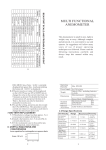
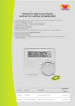
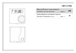
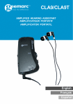
ROOM THERMOSTAT DIGITAL
Installation and user instruction……………page 2
EN
TERMOSTATO AMBIENTE DIGITALE
Manuale di installazione e uso………….…pag. 5
WIRED - manual issue 12/2012 rev. 00
IT
EN
.
ENCODER KNOB
THIS INSTRUCTIONS TO BE RETAINED BY THE USER
Encoder
movements:
clockwise
and
anticlockwise rotation.
Encoder clockwise and anticlockwise
rotation: increase or decrease the room
comfort temperature. The selected value
start to blink 5 times; after this blinking
period the comfort temperature value is automatically entered.
Encoder rotation one step: check the selected comfort
temperature ± 0,2 °C. The value will blink for few times and
later it will be back to the room temperature value display.
Thank you for choosing this thermostat. This central heating
control device is easy to fit, and with correct use, will deliver
improved comfort levels in your home whilst saving you
money.
This thermostat is designed to be used only with heating
controls system with a maximum switching load of 2A at
30VDC or 0,25A at 230VAC.
If installing for someone else, please ensure that the
instructions are handed to the householder.
WARNING: Please read this manual prior to installation or use.
SHOCK HAZARD: This unit must be installed by a competent
person, in accordance with BS 7671 (the IEE Wiring
Regulations), or other relevant national regulations and codes
of good practice. Always isolate the AC Mains supply before
installing this unit.
DISPLAY
IMPORTANT: these instructions should be read in conjunction
with the appliance installation instructions. It is recommended
that this device is installed by a qualified electrician.
ENCODER
SENSOR
OPENING
2
EN
.
INSTALLATION AND OPERATING INSTRUCTIONS
THE THERMOSTAT is wall-mounted
type. It can be located wherever a
conventional room thermostat
would normally be sited. The
thermostat need to be wired with
the boiler only for the room
thermostat connection, no high
voltage supply is required as it is
battery powered. It must be
connected to the boiler.
PACKING LIST
• Time-thermostat
• Screws and wall plugs (drill 5 mm)
• Double side adhesive
• Instructions
• Batteries 1,5 AAA
QTY
1
2
2
1
2
INSTALLATION OF THERMOSTAT
Position the thermostat on a wall surface away from
obstructions and direct heat sources or draughts, in a room
that is warmed by the heating system. The fixing of the
transmitter can be done either with the screws and wall plug or
with the double side adhesive depending on the wall surface
quality (both supplied). See the side diagram as reference to
drill the wall. Distance between 2 holes is 60 mm, drill hole dia.
5 mm.
In the case of using wall plug,
the transmitter box must be
open to fix the screws to the
wall plug from inside the box.
The opening of the transmitter
must be done pressing gently
the lower button and leverage
on the upper side. Fit the
supplied two batteries inside
the transmitter with the direction
as indicated internally.
WARNING! Do not touch the printed circuit board of the
transmitter as it contains electrostatically sensitive
components.
BOILER PREPARATION: Isolate the appliance from the electrical
supply and remove the appliance casing and PCB cover (refer
to boiler installation instructions for
specific details).Identify on the boiler
control board the room thermostat
connection. Connect two wires (not
supplied)
from
the
thermostat
terminals – side picture for thermostat
terminals - to the boiler PCB terminals
(room thermostat terminal) - figure below for a sample boiler
connections. The wiring connection is interchangeable.
IMPORTANT: the link-wire (if fitted) must be removed from room
thermostat terminals. Secure the wiring harness to the internal
boiler cable anchors. Wiring must conform to IEE regulations.
IMPORTANT: This thermostat is designed to be used only with
heating controls system with a maximum switching load of 2A
at 30VDC or 0,25A at 230VAC.
3
EN
.
non-appropriate position, therefore it is necessary to modify
the value on the display to be according the real room
temperature.
WARNING! Avoid to touch thermostat casing especially near
the temperature sensor during the calibration in order do not
alternate the values with the hands heat.
FUNCTIONS
The thermostat has the following functions:
• Room thermostat: the internal temperature sensor detects
the temperature and, comparing with the set point, switches
ON or OFF the heating request. The temperature sensor is
located on the lower side of the item.
• Battery low
• Room temperature calibration
LOW BATTERIES
The two supplied batteries will last for approximately 2 years
under a normal usage. When the batteries are low, the LO
letters will appear on the display alternated to the room
temperature value. Follow the correct positioning of the
batteries according to the internal transmitter battery box
indications. Every time the batteries are removed the set
temperature is maintained memorized. In the case of
completely empty batteries, at the moment of the final
switching OFF, the relay position (and therefore the heat
request) remains as it was in that moment.
TECHNICAL SPECIFICATIONS
Relay switching capacity:
− Min 1mA,
− Max 2A at 30 VDC
− Max 0,25A at 230 VAC
Power rating: 2 x 1,5AAA - Alkaline batteries
Temperature setting: 5°C to 35°C in 0.2°C increment s.
Display temperature: -9°C to 40°C in 0.2°C incremen ts.
Hysteresis OFF: 0,4°C (boiler switch OFF at 0,4°C a bove the
target)
Hysteresis ON: 0,2°C (boiler switch ON at 0,2°C bel ow the
target)
CALIBRATION
It is possible to calibrate the transmitter temperature sensor
with the following procedure:
• Open the transmitter casing
• Identify on the printed circuit board the jumper pins: in
normal use the jumper is inserted between pin 1-2.
• Move the jumper in position 2-3
• Wait up to the display value starts to blink. Now you are
inside the calibration function. Rotating the encoder the
current room temperature can be adjusted.
• Move back the jumper to position 1-2 to enter.
From now the transmitter uses the new value as current room
temperature. Please note that for the calibration it is necessary
to have a second thermometer that will be used as master.
This operation is suggested only if the thermostat is fixed in a
Install the thermostat in an environment with normal pollution
level.
The manufacturer reserves the right to change specification
without prior notice - Consumers statutory rights are not
affected.
4
IT
QUESTE ISTRUZIONI DEVONO ESSERE CONSERVATE DA PARTE
DELL’UTENTE
.
MANOPOLA ENCODER
La selezione della temperatura viene fatta
dall’encoder che può ruotare in senso
orario e antiorario.
Rotazione in senso orario e antiorario:
aumenta o diminuisce la temperatura
“comfort” della stanza; dopo 5 lampeggi il valore di
temperatura scelto viene memorizzato.
Ruotare di uno scatto per verificare il valore impostato di
temperatura ± 0,2°C, dopo pochi lampeggi il display torna a
visualizzare la temperature ambiente.
Grazie per aver scelto questo termostato settimanale. Questo
dispositivo di controllo dell’impianto riscaldamento è di facile
installazione e, se propriamente utilizzato, offre una migliore
qualità di comfort e un maggiore risparmio energetico. Questo
termostato è progettato per sostenere un carico elettrico
massimo di 2A a 30VDC o 0,25A a 230VAC (specifiche del
relè interno di commutazione del collegamento “termostato
ambiente” della caldaia). Se l’installazione è fatta da personale
terzo, assicurarsi che questo manuale sia consegnato
all’utente finale.
ATTENZIONE: Si prega di leggere questo manuale prima di
procedere all'installazione e all'uso.
PERICOLO DI SCOSSE ELETTRICHE: Questo apparecchio deve
essere installato da personale competente e secondo le norme
vigenti in termini di installazioni elettriche. Staccare sempre
l'alimentazione elettrica prima di procedere all’installazione.
DISPLAY
ENCODER
IMPORTANTE: queste istruzioni devono essere lette assieme a
quanto riportato anche sul manuale della caldaia riguardo al
controllo del termostato ambiente. Si raccomanda che il
dispositivo sia installato da personale qualificato.
SENSORE
APERTURA
5
IT
.
INSTALLAZIONE E USO
Il termostato digitale può essere
posizionato ovunque come un
qualsiasi
termostato
ambiente
convenzionale. È necessario il
collegamento mediante due fili tra la
connessione termostato ambiente
della caldaia e il termostato. Non è
necessaria alcuna alimentazione
elettrica in quanto il termostato è
alimentato mediante batterie.
CONTENUTO DELLA SCATOLA
• Termostato
• Tasselli e viti (Ø 5 mm)
• Bi-adesivo
• Manuale d’uso
• Batterie 1,5V TIPO AAA
ricevitore assieme agli altri cavi della caldaia per evitare
strappi accidentali dei fili che potrebbero compromettere la
sicurezza dell’installazione. Il cablaggio deve essere conforme
alle normative IEE.
QTÀ
1
2
2
1
2
INSTALLAZIONE DEL TERMOSTATO
Il termostato va installato in una stanza riscaldata dal sistema
di riscaldamento gestito dal medesimo. Il fissaggio alla parete
può essere fatto mediante i tasselli e le viti (aprire l’involucro) o
utilizzando i due biadesivi tutto fornito a corredo. Vedere
disegno a lato per il riferimento
della foratura, la distanza tra
due fori è di 60 mm, foro Ø 5
mm. Per il funzionamento è
necessario inserire le due
batterie fornite a corredo. Per
inserire le batterie aprire
l’involucro
del
termostato
premendo il tasto posto sul
lato inferiore e fare leva sul
lato superiore. Inserire le due
batterie secondo lo schema
interno.
ATTENZIONE! Non toccare il circuito stampato del termostato in
quanto contiene componenti sensibili alle scariche
elettrostatiche.
PREPARAZIONE DELLA CALDAIA. Isolare
la
caldaia
dall’alimentazione elettrica, aprire il cruscotto dove sono
alloggiati i collegamenti elettrici (per dettagli fare riferimento al
manuale di installazione e uso della caldaia). Collegare
mediante un cavo con due fili (non
forniti) i terminali del termostato (vedi
figura a lato) ai morsetti del termostato
ambiente sulla caldaia assicurandosi
che le caratteristiche elettriche tra
quanto disponibile in caldaia e il relè
del termostato siano compatibili (vedi
paragrafo specifiche tecniche). La non compatibilità comporta
un mal funzionamento e pericolosità dell’installazione. Vedi
immagine successiva per una installazione tipica. La posizione
dei due fili rispetto ai morsetti è indifferente.
IMPORTANTE: il ponticello (se presente) deve essere rimosso
dai morsetti termostato ambiente. Ancorare il cablaggio del
6
IT
.
Da questo momento il sensore di temperatura utilizza il nuovo
valore come riferimento. Per una corretta taratura serve un
termostato di paragone. Questa operazione è consigliata solo
se il termostato si trova in una posizione non adeguata e che
necessita pertanto di una variazione del riferimento per
rendere veritiero il valore visualizzato rispetto alla reale
temperatura dell’ambiente.
ATTENZIONE! Evitare di toccare, durante la taratura, l’involucro
del termostato per non alterare i valori con il calore della mani
FUNZIONI
Il termostato fornisce le seguenti funzionalità:
• Termostato ambiente: il sensore di temperatura interna
rileva la temperatura e, confrontandola con la temperatura
impostata (set point), attiva o disattiva la richiesta di
riscaldamento. Il sensore di temperatura si trova sul lato
inferiore del termostato.
• Batterie scariche
• Calibratura del sensore temperatura ambiente
BATTERIE SCARICHE
Le due batterie in dotazione sono garantite per durare almeno
2 anni per un normale utilizzo dell’apparecchio. Quando le
batterie sono scariche la relativa icona apparirà sul display.
Meglio cambiare batterie in tempo per evitare richieste
sbagliate di riscaldamento. Ogni volta che vengono rimosse le
batterie viene cancellata l’ora; le altre impostazioni rimangono
memorizzate. Nel caso di completo scaricamento delle
batterie, il relè (e di conseguenza la richiesta o meno di calore)
mantiene la stessa posizione avuta al momento del completo
spegnimento.
SPECIFICHE TECNICHE
Capacità di commutazione relè:
− Min 1mA,
− Max 2A a 30 Vc.c.
− Max 0,25 A a 230 VAC
Alimentazione: 2 batterie di tipo 1,5AAA
Impostazione delle temperature: da 5°C a 35°C in ri soluzione
di 0,2°C
Visualizzazione delle temperatura: da -9°C a 40°C i n
risoluzione di 0,2 °C
Isteresi OFF: 0,4 °C (il riscaldamento viene spento a 0,4 °C al
di sopra del target impostato)
Isteresi ON: 0,2 °C (il riscaldamento viene acceso a 0,2 °C
sotto il target impostato)
TARATURA SENSORE AMBIENTE
È possibile calibrare il sensore di temperatura del termostato
con la seguente procedura:
• Aprire l’involucro del termostato premendo il pulsante posto
sul lato inferiore.
• Individuare sul circuito stampato il connettore con jumper
inserito: posizione normale è tra i pin 1-2
• Spostare il jumper su posizione 2-3
• Aspettare fino a quando il display non inizia a lampeggiare.
Ora si è all’interno della funzione calibratura, ruotare la
manopola per cambiare il valore di riferimento.
• Spostare il jumper su posizione 1-2 per confermare il nuovo
riferimento ed uscire dalla funzione
Installare termostato e ricevitore in un ambiente con un
normale quantità di polvere.
Il costruttore si riserva di variare le caratteristiche e i dati
riportati nel presente manuale in qualunque momento e senza
preavviso, nell’intento di migliorare il prodotto.
7