1
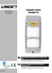
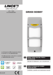
LINCE ITALIA S.p.A.
NEMO-I
ART. / ITEM: 1812NEMO-I
LINCE ITALIA S.p.A.
Via Variante di Cancelliera, snc
00040 ARICCIA (Roma)
Tel. +39 06 9301801
Fax +39 06 930180232
[email protected]
www.lince.net
NEMO-L
ART. / ITEM: 1813NEMO-L
001530/00767AB
REG.N.4796
UNI EN ISO 9001:2008
IT
SIRENA PIEZOELETTRICA PER INTERNO
Manuale di installazione, uso e manutenzione
EN
INDOOR PIEZOELECTRIC SIREN
Installation, operation and maintenance manual
- Istruzioni originali -
- Translation of the original instructions (original instructions in Italian) -
Le informazioni riportate in questo manuale sono state compilate con
cura, tuttavia LINCE ITALIA S.p.A. non può essere ritenuta responsabile
per eventuali errori e/o omissioni. LINCE ITALIA S.p.A. si riserva il diritto
di apportare in ogni momento e senza preavviso, miglioramenti e/o
modifiche ai prodotti descritti nel presente manuale. Consultare il sito
www.lince.net per le condizioni di assistenza e garanzia.
LINCE ITALIA S.p.A. pone particolare attenzione al rispetto
dell'ambiente. Tutti i prodotti ed i processi produttivi sono progettati con
criteri di eco-compatibilità.
The information in this manual has been issued with care, but LINCE
ITALIA S.p.A. will not be responsible for any errors or omissions.
LINCE ITALIA S.p.A. reserves the right to improve or modify the
products described in this manual at any time and without advance
notice. Terms and conditions regarding assistance and the product
warranty can be found at LINCE ITALIA's website www.lince.net.
LINCE ITALIA S.p.A. makes it a priority to respect the environment. All
products and production processes are designed to be eco-friendly and
sustainable.
1.
1.
INTRODUZIONE
Il manuale descrive le modalità di installazione e uso delle sirene
piezoelettriche da interno 1812NEMO-I e 1813NEMO-L.
La sirena è il principale dispositivo di segnalazione degli allarmi nei
sistemi di sicurezza a cui deve essere dato un alto grado di sicurezza e
di affidabilità nel tempo.
1.1
CARATTERISTICHE GENERALI
La sirena è disponibile in due versioni che si distinguono per il tipo di
alimentazione e la presenza o meno del lampeggiatore:
NEMO-I
NEMO-L
Lampeggiatore
No
Si
Autoalimentata
No
Si
INTRODUCTION
The manual describes the operating and installation methods of the
1812NEMO-I and 1813NEMO-L indoor piezoelectric sirens.
The siren is the main alarm signalling device in security systems and
must be equipped with high level security and reliability over time.
1.1
GENERAL FEATURES
The siren is available in two versions that are distinguished by the type
of power and the presence of the flashing light:
NEMO-I
NEMO-L
Flashing light
No
Yes
Self-powered
No
Yes
Tutte le versioni sono dotate:
– di un trasduttore piezoelettrico per la segnalazione acustica;
– di un dispositivo antisabotaggio che segnala la rimozione del
coperchio e/o lo strappo dal muro.
La versione NEMO-L è dotata di LED per la segnalazione ottica ed,
inoltre, di una batteria tampone che ne garantisce il funzionamento
anche in assenza di alimentazione.
All versions are equipped with:
– a piezoelectric transducer for acoustic signalling;
– an anti-tamper device that indicates the removal of the lid and/or the
removal from the wall.
The NEMO-L version is equipped with LEDs for visual indication, and a
backup battery that guarantees operation even in the event of a power
cut.
1.2
1.2
CARATTERISTICHE TECNICHE
Alimentazione
Assorbimento in allarme
Pressione sonora
Grado di protezione
Temperatura di funzionamento
Dimensioni esterne (LxAxP)
Peso (senza batteria)
Batteria tampone
NEMO-I
NEMO-L
Made in PRC
Made in Italy
NEMO-I / NEMO-L
NEMO-I
NEMO-L
13,8 Vcc
13,8 Vcc
Power
TECHNICAL FEATURES
NEMO-I
NEMO-L
13,8 Vdc
13,8 Vdc
180 mA (max)
225 mA
Power usage in alarm mode
120 mA (max)
225 mA
100 ±3 dB a 1 m
100 ±3 dB a 1 m
Acoustic alarm sound level
100 ±3 dB at 1 m
100 ±3 dB at 1 m
IP 31
IP 31
IP 31
IP 31
+10 °C / +40 °C
+10 °C / +40 °C
155 x 136 x 38 mm
155 x 136 x 38 mm
180 g (max)
180 g (max)
-
1/3AA 300 mAh 7,2 V
Protection level
Operating temperature
External dimensions (WxHxD)
Weight (no battery)
Buffer battery
NEMO-I
NEMO-L
+10 °C / +40 °C
+10 °C / +40 °C
155 x 136 x 38 mm
155 x 136 x 38 mm
180 g (max)
180 g (max)
-
1/3AA 300 mAh 7,2 V
Made in PRC
Made in Italy
1
LINCE ITALIA S.p.A.
2.
INSTALLAZIONE
2.
INSTALLATION
2.1
DOTAZIONI DI SERIE
2.1
STANDARD EQUIPMENT
Fare riferimento alla fig. 1 per l'identificazione delle dotazioni di serie.
2.2
INSTALLAZIONE A PARETE
Refer to fig. 1 to identify the standard equipment.
2.2
WALL INSTALLATION
Le seguenti operazioni devono essere effettuate da personale qualificato e specializzato.
Prima dell'installazione verificare le seguenti condizioni:
• la sirena deve essere installata all'interno dei locali;
• la parete non deve presentare avvallamenti o sporgenze eccessive
per non compromettere il funzionamento del dispositivo antistrappo.
• Nell'effettuare i fori per il fissaggio, fare attenzione a non danneggiare fili o tubi sotto traccia.
The following operations must be carried out by qualified and specialist personnel.
Before starting the installation, make sure that:
• the siren should be installed indoors;
• the wall does not have any pronounced depressions or protrusions:
these can prevent the wall tamper device from operating correctly.
• When drilling the mounting holes, be careful not to damage
concealed wires or pipes.
Fasi di installazione
• Svitare e rimuovere una delle due viti 3 (fig. 1) ed aprire il coperchio
2.
• Posizionare il fondo della sirena sulla parete e tracciare i fori di riferimento, di cui: segnare una traccia nel foro F1 (in basso a destra per
attivare la funzione antistrappo) ed un'altra scegliendone uno dei fori
F2 (fig. 2).
• Sulla parete praticare i 2 fori utilizzando un utensile adeguato ed installare i tasselli (in dotazione). Verificare, inoltre, che il tassello in
basso a destra (antistrappo) sia correttamente fissato.
• I due fori centrali FB (fig. 2) sono predisposti per l'installazione della
sirena su una scatola elettrica da incasso; in questo caso segnare
una traccia nel foro F1 (in basso a destra per attivare la funzione antistrappo) ed un'altra scegliendo uno dei fori FB.
• Passare il cavo per i collegamenti attraverso i fori 8 (pretagli) posti
sul fondo (fig. 2).
• Una volta inseriti i tasselli nel muro, posizionare la sirena sulla parete e
fissare con le due viti (in dotazione).
• Impostare il tipo di suono desiderato come indicato al par. 2.3.
• Procedere con il collegamento elettrico come descritto al par. 2.4.
• Solo mod. NEMO-L: posizionare la batteria tampone nel suo alloggiamento (rif. 9, fig. 2) ed effettuare il collegamento come indicato al
par. 2.4.
• Ad operazioni concluse: chiudere il coperchio, posizionare nel suo
alloggiamento la vite 3 precedentemente rimossa ed avvitarla fino al
completo fissaggio.
Installation steps
• Loosen and remove one of the 2 screws (ref. 3, fig. 1) and open the
lid (2).
• Place the backplate of the siren on the wall and mark the reference
holes: mark the F1 hole (lower right to activate the wall tamper function) and another by choosing one of the F2 holes (see fig. 2).
• Make 2 holes in the wall using an appropriate tool and insert the
plugs (supplied). Check that the bottom right plug (wall tamper) is fastened correctly.
• The two central FB holes (fig. 2) are set-up for the siren to be installed on a recessed electrical box; in this case, mark the F1 hole (lower right to activate the wall tamper function) and another by choosing one of the FB holes.
• Pass the connection cable through the holes (ref. 8, pre-cut) on the
backplate (fig. 2).
• Once the plugs are inserted into the wall, place the siren on the wall
and fasten it with the 2 screws (supplied).
• Set the type of desired acoustic alarm as described in par. 2.3.
• Set up the electrical connection as described in par. 2.4.
• Only mod. NEMO-L: place the backup battery in its housing (ref. 9,
fig. 2) and connect as described in par. 2.4.
• Once completed: close the lid, place the previously removed screw
(3) in its housing and tighten it until it is securely fastened.
2.3
IMPOSTAZIONE DEL TIPO DI SUONO
2.3
La sirena può emettere due diversi tipi di suoni in base alla posizione del
ponticello J1.
J1
J1
2.4
TIPO DI SUONO
COLLEGAMENTO ELETTRICO
Per i collegamenti usare sempre cavi schermati con un capo dello
schermo collegato alla massa della centrale e l'altro, quello verso la
sirena, lasciato libero. Se i collegamenti sono molto lunghi verificare che
non vi sia caduta di tensione.
Descrizione dei morsetti per il collegamento (fig. 3, 4, 5)
Su questo morsetto è presente una tensione continua di 13,8 V.
Two-tone
2.4
Description of the connection terminal blocks (fig. 3, 4, 5)
There is a direct current at 13.8 V on this terminal block.
NEMO-L Power: 13,8 Vdc / 25 mA (max)
12V
+N / -A
AS
Ingresso di controllo NEMO-I
La sirena è nello stato di riposo quando il morsetto 12 V è appeso;
la sirena si attiva quando il morsetto 12 V è collegato al positivo
(13,8 V).
Ingresso di controllo NEMO-L
La sirena è nello stato di riposo quando il morsetto +N è collegato
al positivo (13,8 V) ed il morsetto -A è collegato alla massa.
La sirena si attiva quando i morsetti +N o -A restano appesi.
Antisabotaggio.
I morsetti AS sono collegati fra loro quando il microswitch 6 (fig. 2)
è chiuso; sono scollegati fra loro quando il microswitch 6 è aperto.
ELECTRICAL CONNECTION
Always use shielded cables for the connections, with one end of the
shield connected to the ground of the control unit and the other, which
goes towards the siren, left free. If the connections are very long, check
that there is no power loss.
Alimentazione NEMO-L: 13,8 Vcc / 25 mA (max)
12V
TYPE OF ACOUSTIC ALARM
Up and down (default) modulation
Modulazione in salita e discesa (default)
Bitono
SETTING THE TYPE OF ACOUSTIC ALARM
The siren can emit two different types of acoustic alarm according to the
position of jumper J1.
NEMO-I control input
The siren is in the idle state when the 12 V terminal block is open;
the siren is activated when the 12 V terminal block is connected to
the positive (13.8 V).
+N / -A
NEMO-L control input
The siren is in the idle state when the +N terminal block is connected to the positive (13.8 V) and the -A terminal block is connected
to the ground.
The siren is activated when the +N or -A terminal blocks remain
open.
AS
Anti-tamper.
The AS terminal blocks are interconnected when micro switch 6
(fig. 2) is closed; and disconnected when micro switch 6 is open.
Power supply negative (ground).
Negativo di alimentazione (massa).
2
NEMO-I / NEMO-L
LINCE ITALIA S.p.A.
2.4.1
Collegamento elettrico NEMO-I
Eseguire le seguenti operazioni (fig. 3):
1. collegare il morsetto 12V ad un positivo presente in centrale in fase
di allarme e il morsetto (
) alla massa;
2. collegare il morsetto AS alla linea antisabotaggio di una centrale di
allarme.
2.4.1
NEMO-I electrical connection
Perform the following operations (fig. 3):
1. connect the 12V terminal block to a positive signal when the alarm is
setted and the (
) terminal block to the ground;
2. connect the AS terminal block to the anti-tamper line of an alarm
control panel.
2.4.2
2.4.2
Collegamento elettrico NEMO-L
NEMO-L electrical connection
• PROCEDURA DI COLLEGAMENTO TRAMITE MORSETTO: +N
Eseguire le seguenti operazioni (fig. 4):
1. rimuovere il ponticello J3;
2. collegare il morsetto -A alla massa (
);
3. collegare l'alimentazione al morsetto 12V ed alla massa (
)
rispettandone la polarità (+ / -);
4. collegare il morsetto AS alla linea antisabotaggio di una centrale di
allarme.
• CONNECTION PROCEDURE VIA TERMINAL BLOCK: +N
Perform the following operations (fig. 4):
1. remove the jumper J3;
2. connect the terminal block -A to the ground (
);
3. connect the power supply to the 12V terminal block and the ground
(
) with the correct polarity (+ / -);
4. connect the AS terminal block to the anti-tamper line of an alarm
control panel.
• PROCEDURA DI COLLEGAMENTO TRAMITE MORSETTO: -A
Eseguire le seguenti operazioni (fig. 5):
1. inserire il ponticello J3;
2. collegare l'alimentazione al morsetto 12V ed alla massa (
) rispettandone la polarità (+ / -);
3. Collegare il morsetto AS alla linea antisabotaggio di una centrale di
allarme.
• CONNECTION PROCEDURE VIA TERMINAL BLOCK: -A
Perform the following operations (fig. 5):
1. insert the jumper J3;
2. connect the power supply to the 12V terminal block and the ground
(
) with the correct polarity (+ / -);
3. Connect the AS terminal block to the anti-tamper line of an alarm
control panel.
2.5
2.5
SEGNALAZIONI DELLA SIRENA
2.5.1
Allarmi
La segnalazione della condizione di allarme avviene per mezzo di un
suono modulato in frequenza (tutti i modelli) e di un lampeggiatore (solo
mod. NEMO-L).
Per rispondere alle normative vigenti, la segnalazione acustica dura al
massimo 5 minuti, mentre quella ottica permane fino a quando non
vengono ripristinate le condizioni di normale funzionamento.
3.
MANUTENZIONE E VERIFICHE PERIODICHE
3.1
CONTROLLO E SOSTITUZIONE DELLA BATTERIA
Solo mod. NEMO-L.
La batteria garantisce l'alimentazione in caso di mancanza di rete
elettrica.
Si consiglia di controllare periodicamente l'efficienza della batteria della
sirena e provvedere alla sostituzione ogni 3 anni.
Materiale da utilizzare: cacciavite - batteria nuova.
Procedura di sostituzione:
1. Svitare e rimuovere una delle due viti 3 (fig. 1) ed aprire il coperchio
2.
2. Rimuovere il ponticello JP2 della batteria (rif. 9, fig. 2) e rimuoverla
dal suo alloggiamento.
3. Installare la nuova batteria ponendo attenzione alla polarità.
Nota: la batteria nuova deve avere caratteristiche uguali all'originale.
4. Inserire il ponticello JP2.
5.2
PULIZIA DELLA SIRENA
Periodicità: quando necessario o in condizione di sporcizia evidente.
Materiale da utilizzare: panno - acqua senza additivi.
Procedura di pulizia:
ATTENZIONE!
Per rimuovere sporcizie particolarmente evidenti NON
utilizzare prodotti a base di cloro, prodotti abrasivi
oppure alcool.
1.
2.
Pulire il coperchio con un panno inumidito con sola acqua.
Ripassare con un panno asciutto.
NEMO-I / NEMO-L
SIREN ALERTS
2.5.1
Alarms
The signalling of the alarm occurs by means of a frequency modulated
acoustic alarm (all models) and a flashing light (only mod. NEMO-L).
To comply with current regulations, the acoustic alarm lasts a
maximum of 5 minutes. The flashing light, however, continues until
normal operation is restored.
3.
MAINTENANCE AND PERIODIC CHECKS
3.1
CHECKING AND REPLACING THE BATTERY
Only mod. NEMO-L.
The battery guarantees power in the event of a blackout.
It is recommended to periodically check the efficiency of the siren's
battery, which must be replaced every 3 years.
Material to be used: screwdriver - new battery.
Replacement procedure:
1. Loosen and remove one of the 2 screws (ref. 3, fig. 1) and open the
lid (2).
2. Remove the jumper JP2 of the battery (ref. 9, fig. 2) and remove it
from its housing.
3. Install the new battery paying attention to its polarity.
Note: the new battery must have the same characteristics as the
original one.
4. Insert the jumper JP2.
5.2
CLEANING THE SIREN
Frequency: when necessary or when clearly dirty.
Material to be used: cloth - water with no additives.
Cleaning procedure:
IMPORTANT!
Do NOT use chlorine-based or abrasive products or
alcohol to remove particularly noticeable dirt.
1.
2.
Clean the lid with a damp cloth with clear water.
Wipe with a dry cloth.
3
LINCE ITALIA S.p.A.
4
4
10
9
5
12
7
6
11
3
2
1
3
Fig. 1 – Componenti generali e dotazioni di serie / General components and standard equipment
LEGENDA:
1 Coperchio flash
2 Coperchio
3 Viti chiusura
4 Dadi di serraggio
5 Morsettiera
6 Microswitch (antiapertura / antistrappo)
7 Scheda elettronica
8 Parti pretagliate per passaggio cavi
9 Vano batteria tampone
10 Fondo
11 Kit elementi di fissaggio (in dotazione)
12 Manuale (in dotazione)
F2
F2
8
10
5
9
KEY:
1 Flash lid
2 Lid
3 Fastening screws
4 Clamping nuts
5 Terminal block
6 Micro switch (anti-opening / wall tamper)
7 Electronic board
8 Pre-cut parts to allow the cable to pass through
9 Backup battery compartment
10 Backplate
11 Fastening components kit (supplied)
12 Manual (supplied)
8
Sirena / Siren
7
Centrale / Control panel
8
5
FB
FB
8
F2
F1
6
Fig. 2 - Particolare del fondo / Detail of the backplate
Fig. 4 - Collegamento NEMO-L (+N) / NEMO-L (+N) connection
Sirena / Siren
Sirena / Siren
Centrale / Control panel
5
Centrale / Control panel
5
5
Fig. 3 - Collegamento NEMO-I / NEMO-I connection
4
Fig. 5 - Collegamento NEMO-L (-A) / NEMO-L (-A) connection
NEMO-I / NEMO-L