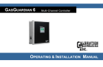
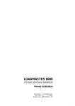
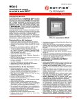
1
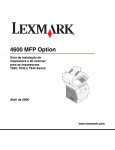
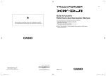
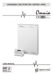
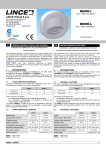
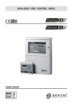
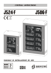
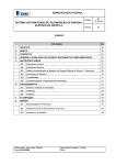
ISO 9001 IT-52587 O HSAS 18001 O HSAS 18001 9192.BSEC IT - 60983 ISO 14001 9191.BNT2 ISO 14001 IT-52588 ISTISBL2WAVE-W 0.6 201009 P7.0 ISO 9001 9105.BNT1 I ITALIANO ! Una tensione di 250 V_ _ è presente su alcuni punti della scheda elettronica di questo dispositivo: togliere l’alimentazione e aspettare almeno 2 minuti prima di intervenire sulla scheda elettronica. ! Questo dispositivo utilizza batterie al Nichel-Cadmio che devono essere smaltite in conformità alle legislazioni nazionali. ! Le versioni autoalimentate (Wave/WSB e Wave/WB) devono essere tenute in carica almeno 24 ore per funzionare in modo corretto. 5. Fare pressione con un giravite, sul dente 9, per separare la Staffa 12 dal Fondo 10. 6. Passare il cavo per i collegamenti attraverso l’apertura 13. 7. Fissare la Staffa 12 alla parete o alla scatola predisposta tramite le asole opportune. Per il funzionamento dell’antistrappo l’asola 14 (fig.1) deve sempre essere fissata al muro o alla scatola predisposta con una vite. ! 8. 9. CARATTERISTICHE GENERALI Disponibile nelle versioni autoalimentata e non, con lampeggiatore e senza 2 tipi di suono selezionabili Rilevazione del sabotaggio (antiapertura e antistrappo) Staffa universale per l’installazione in ogni situazione La sirena Wave è un dispositivo per la segnalazione degli allarmi in sistemi di sicurezza. Essa è disponibile in quattro versioni che si distinguono per il tipo di alimentazione e la presenza o meno del lampeggiatore. Versione Lampeggiatore Autoalimentata Wave/WSB SI SI Wave/WB no SI Wave/WS SI no Wave/W no no Tutte le versioni sono dotate di un trasduttore piezoelettrico per la segnalazione acustica, inoltre, le versioni Wave/WS e Wave/ WSB sono dotate di una lampada allo Xenon per la segnalazione ottica. Le versioni Wave/WB ed Wave/WSB sono dotate di una batteria tampone da 7,2 V – 300 mA (art. CB7203) che ne garantisce il funzionamento anche in assenza di alimentazione. Tutte le versioni sono dotate di morsetti antisabotaggio che segnalano la rimozione del coperchio e/o lo strappo dal muro. INSTALLAZIONE Per l’installazione di questa Sirena procedere come descritto di seguito (vedere la Figura 1) Questa Sirena deve essere installata all’interno di locali. 1. 2. 3. 4. 11. 12. 13. DESCRIZIONE GENERALE 10. Rimuovere con un giravite piatto il Tappo 5. Svitare la vite 4. Togliere il Coperchio 3 tirandolo dal lato superiore. Togliere la Lente 2. Nel praticare i fori per il fissaggio fare attenzione a non danneggiare fili e tubi sottotraccia. Passare il cavo per i collegamenti attraverso l’apertura 11. Appoggiare il Fondo 10 sulla Staffa 12, quindi farlo scorrere verso il basso fino ad agganciarlo. Impostare il Tipo di Suono desiderato, come descritto nel paragrafo omonimo. Eseguire i collegamenti sulla Morsettiera 7 come descritto nel paragrafo omonimo. Riagganciare la Lente 2. Solo Wave/WSB e Wave/WB: posizionare la Batteria 6 come mostrato in Figura 1, quindi collegarla al connettore J5. ! Solo Wave/WSB e Wave/WB: prima di collegare la batteria, assicurarsi che sul morsetto +B sia presente il positivo (13.8 V), che sul morsetto +N sia presente il positivo (13.8 V) oppure che il ponticello J3 sia inserito, che sul morsetto –A sia presente la massa, altrimenti la sirena entrerà in funzione! 14. Appoggiare il Coperchio 3 al Fondo 10, quindi premere sugli angoli inferiori. 15. Avvitare la vite 4. 16. Riposizionare il tappo 5. TIPO DI SUONO La Sirena può emettere due suoni diversi in base alla posizione del ponticello J15: J15 TIPO DI SUONO Modulazione in salita e discesa (Default) Bitono COLLEGAMENTI Per i collegamenti usare cavo schermato con un capo dello schermo collegato alla massa della centrale e l’altro capo lasciato appeso. In Figura 2 è mostrato un esempio di collegamento per attivare la sirena Wave/WB o Wave/WSB, tramite il morsetto +N. Quando si usa il morsetto +N per l’attivazione della Sirena, il ponticello J3 deve essere rimosso e il morsetto -A deve essere collegato alla massa (morsetto ). In Figura 3 è mostrato un esempio di collegamento per attivare la sirena Wave/WB o Wave/WSB, tramite il morsetto –A. Quando si usa il morsetto –A per l’attivazione della Sirena, il ponticello J3 deve essere inserito. BATTERIA TAMPONE Usare solo una batteria tampone (6) da 7,2 V tipo CB7203 o equivalente: questa batteria garantisce la tenuta dell’alimentazione in caso di mancanza della rete elettrica. Per sostituire la Batteria Tampone, procedere come descritto di seguito (fare riferimento alla Fig. 1). 1. Staccare il connettore J5. 2. Rimuovere la batteria 6. 3. Inserire la nuova batteria. In Figura 4 è mostrato un esempio di collegamento della sirena Wave/W o Wave/WS. Gli esempi A e B mostrano due configurazioni di morsetti di centrali antifurto, per il collegamento della Sirena. Nelle Figure 2, 3 e 4 si presume che: ¾ sul morsetto +B è presente una tensione continua di 13.8 V; ¾ sul morsetto +N è presente il positivo (13.8 V) quando la centrale è nello stato di riposo, mentre è appeso quando la centrale è nello stato di allarme; ¾ il morsetto NC è collegato al morsetto COM quando la centrale è nello stato di riposo, mentre è appeso quando la centrale è nello stato di allarme; ¾ il morsetto NO è appeso quando la centrale è nello stato di riposo, mentre è collegato al morsetto COM quando la centrale è nello stato di allarme; ¾ il morsetto OC è collegato alla massa (morsetto -) quando la centrale è nello stato di riposo, mentre è appeso quando la centrale è nello stato di allarme; ¾ sul morsetto +A è presente il positivo (13.8 V) quando la centrale è nello stato di allarme, mentre è appeso quando la centrale è nello stato di riposo. Se deve essere rilevato il sabotaggio della Sirena, collegare i morsetti AS in serie alla linea antisabotaggio della centrale. 4. ! Pericolo di ESPLOSIONE se la Batteria Tampone è sostituita con altra di tipo scorretto. Le batterie usate devono essere eliminate nei siti predisposti, in accordo alle norme vigenti. Inserire il connettore J5 della nuova batteria. CARATTERISTICHE TECNICHE AS +B +N –A DESCRIZIONE MORSETTI Antisabotaggio: i morsetti AS sono collegati fra loro quando il deviatore antisabotaggio 8 è chiuso; sono scollegati quando il deviatore antisabotaggio 8 è aperto. Alimentazione (Wave/WB e WSB): 13,8 V; 25 mA Max. Ingresso di Controllo (Wave/W e WS):la sirena è nello stato di riposo quando il morsetto +B è appeso; la sirena si attiva quando il morsetto +B è collegato al positivo (13,8 V). Ingressi di Controllo (Wave/WB e WSB): la Sirena è nello stato di riposo quando il morsetto +N è collegato al positivo (13,8 V) e il morsetto –A è collegato alla massa; la Sirena si attiva quando il morsetti +N o –A restano appesi. Massa Tensione di Alimentazione 13,8 V Corrente Assorbita (+B): Wave/WB e Wave/WSB Wave/W Wave/WS 25 mA Max. 90 mA 225 mA Batteria (art. CB7203) 1/3AA 300 mAh 7,2 V Pressione Sonora 104 ±3 dB a 1 m Intensità Luminosa 60 cd Grado di Protezione Temperatura di Funzionamento Dimensioni (L x H x P) Peso IP31 5 ÷ 40 °C 126 x 132 x 53 mm 310 g Max. Wave/WSB MADE IN ITALY Wave/WB MADE IN ITALY Wave/WS MADE IN ITALY Wave/W MADE IN PRC G ENGLISH ! Do not touch the PCB for at least 2 minutes after remov_ may still be present across ing the power supply: 250 V_ the PCB circuitry of this device. ! This device is designed to work with Nickel-Cadmium batteries. When disposing of used batteries, abide by the Local laws in force. ! The self-powered versions (Wave/WSB and Wave/WB) must be powered for at least 24 hours to ensure that the battery is fully charged. 12. Replace the Lens cover 2. 13. For Wave/WSB and Wave/WB only: locate the battery 6, as per Figure 1, then connect it to the input J5. ! For Wave/WSB and Wave/WB only: before connecting the battery, ensure that: the Positive Voltage (13.8 V) is on terminal +B; the Positive Voltage (13.8 V) is on terminal +N or jumper J3 is connected; Ground is present on –A. 14. Snap the top of the Lid 3 onto the Backplate 10, then push the bottom part onto the backplate posts. 15. Replace the Closure screw 4. 16. Replace the Logo Insert 5. GENERAL FEATURES SELECTING THE SOUND TYPE Two different sounds are selectable via jumper J15: Available with or without back-up battery, with or without Strobe 2 selectable sound types Tamper detection (tamper and snatch tamper) Universal Wall mount bracket GENERAL DESCRIPTION The Wave HornStrobe is an Audible-Visual Alarm signalling device for Security Systems. It is available in four versions, as per the following table. Version Strobe Back-up Battery Wave/WSB YES YES Wave/WB no YES Wave/WS YES no Wave/W no no All versions have piezoelectric transducers for audible signalling, whereas only the Wave/WSB and Wave/WS versions are fitted with Strobes for visual signalling. The Wave/WSB and Wave/WB versions are fitted with 7.2 V – 300 mA batteries (art. CB7203) for back-up power during blackout. All versions have tamper terminals that signal the removal of the Lid and the snatch. INSTALLATION GUIDELINES Carefully work through the following steps (see Figure 1). This HornStrobe is suitable for indoor use only. 1. 2. 3. 4. 5. Remove the Logo Insert 5. Remove the screw 4. Pull the Lid 3 upwards and away from the backplate. Remove the Lens cover 2. Using a screwdriver or similar tool, push down on the locking tab 9 and push the Wall bracket 12 away from the Backplate 10. 6. Pull the connection wires through the cable entry 13. 7. Using anchor screws, secure the Wall bracket 12 to the wall or to the outlet box. Snatch Tamper functions ONLY when a screw is properly fixed in the hole 14 (figure.1). ! Be careful to avoid conduits and plumbing when drilling. 8. Pull the connection wires through the cable entry 11. 9. Slide the Backplate 10 downwards onto the Wall bracket 12 until it snaps closed. 10. Select the required sound type, as per the instructions in the relevant section. 11. Complete the connections on the terminal board 7, as per the instructions in the relevant section. J15 SOUND TYPE Up and Down scale modulation (Default) Bitone CONNECTIONS Use shielded cable for the connections. One end of the cable must be connected to Ground on the Panel, and the other left free. Examples A and B in the wiring diagram in Fig. 2 utilize terminal +N to activate Wave/WB or Wave/WSB. Only use a buffer battery (6) with a value of 7.2 V, type CB7203 or equivalent: this battery maintains the power supply if the electricity is cut off for any reason. To replace the buffer battery, proceed as follows (refer to Fig. 1). 1. Disconnect connector J5. 2. Remove the battery 6. 3. Insert the new battery. When using terminal +N to activate the device, jumper J3 must be disconnected and terminal -A must be connected to Ground (terminal ). Examples A and B in the wiring diagram in Fig. 3 utilize terminal –A to activate Wave/WB or Wave/WSB. BATTERY 4. ! Risk of EXPLOSION if the buffer battery is replaced with a different – and therefore incorrect – type. The exhausted batteries used must be disposed of at special sites, in accordance with current legislation. Fit connector J5, corresponding to the new battery. When using terminal –A to activate the device, jumper J3 must be connected. When connecting either Wave/W or Wave/WS refer to Examples A and B in the wiring diagram in Fig. 4. Examples A and B in the Wiring diagrams show the connection of Wave Series devices to two different types of Panel terminal boards. The acronyms that identify the terminals in the wiring diagrams (Figures 2, 3 and 4) are valid for Custom Panels only, therefore, when connecting the device to Non-Custom Panels consider that: ¾ terminal +B supplies a 13.8 V Direct Current; ¾ terminal +N supplies the Positive Voltage (13.8 V) during Panel Standby status, whereas it is open (floating) during Alarm status; ¾ terminal NC is closed to terminal COM during Panel Standby status, whereas it is open (floating) during Alarm status; ¾ terminal NO is open (floating) during Panel Standby status, whereas it is closed to Terminal COM during Alarm status; ¾ terminal OC is closed to Ground (terminal -) during Panel Standby status, whereas it is open (floating) during Alarm status; ¾ terminal +A supplies the Positive Voltage (13.8 V) during Panel Alarm status, whereas it is open (floating) during Standby status. If Tamper detection is required: connect terminals AS in series to the Panel tamper line. TECHNICAL SPECIFICATIONS AS +B +N –A TERMINAL DESCRIPTION Tamper: terminals AS will close when the Tamper Switch 8 closes; and will open when the Tamper Switch 8 opens. Power (Wave/WB and WSB): 13.8 V; 25 mA Max. Control Input (Wave/W and WS): The device will hold Standby status while Terminal +B is open (floating). The device will activate when terminal +B connects to the Positive Voltage (13.8 V). Control Inputs (Wave/WB and WSB): The device will hold standby status while terminal +N is connected to the Positive Voltage (13.8 V) and terminal –A is connected to Ground; the device will activate when either terminal +N or –A opens (floating). Ground Operating Voltage Current draw (+B): Wave/WB and Wave/WSB Wave/W Wave/WS Battery (art. CB7203) Sound output Candela Protection Rating Operating Temperature Range Dimensions (L x H x P) Weight 13.8 V 25 mA Max. 90 mA 225 mA 1/3AA 300 mAh 7.2 V 104 ±3 dB at 1 m 60 cd IP31 5 °C to 40 °C 126 x 132 x 53 mm 310 g Max. Wave/WSB MADE IN ITALY Wave/WB MADE IN ITALY Wave/WS MADE IN ITALY Wave/W MADE IN PRC E ESPAÑOL ! En algunos puntos de la tarjeta electrónica de este dis_: corte la alimentapositivo hay una tensión de 250 V_ ción eléctrica y espere almenos dos minutos antes de empezar cualquier operación en la tarjeta. ! Este dispositivo utiliza pilas de níquel-cadmio: se recomienda eliminarlas de acuerdo a las normativas nacionales. ! Las versiones autoalimentadas (Wave/WSB y Wave/ WB) deben alimentarse durante al menos 24 horas para asegurarse de que la batería está completamente cargada. CARACTERÍSTICAS GENERALES Disponible en las versiones: autoalimentada y no autoalimentada, con y sin destellador. Dos tipos de sonido seleccionables. Detección de sabotaje (tamper antisabotaje y tamper trasero). Soporte universal, apto para cualquier situación de instalación. DESCRIPCIÓN GENERAL La sirena WAVE es un dispositivo de señalización de alarmas para sistemas de seguridad. Se encuentra disponible en cuatro versiones, de acuerdo al tipo de alimentación (automática o no) y a la presencia o menos del destellador. Versión Destellador Autoalimentada Wave/WSB SÍ SÍ Wave/WB no SÍ Wave/WS SÍ no Wave/W no no Todas las versiones cuetan con un transductor piezoeléctrico para señalización acústica. Además, las versiones Wave/WS y Wave/WSB montan una lámpara de gas de xenón para señalización óptica. Las versiones Wave/WS y Wave/WSB montan una batería auxiliar de 7,2 V – 300 mA (art. CB7203) que permite su funcionamiento incluso en caso de fallo en suministro de electricidad. Todas las versiones están equipadas con bornes anti-sabotaje para señalización de tapa abierta y del tamper trasero. INSTALACIÓN Para la instalación de esta sirena, proceda según lo indicado a continuación (ver Figura 1). Esta sirena debe ser instalada en lugar cerrado. 1. 2. 3. 4. 5. Quite el tapón 5 con un destornillador plano Desenrosque el tornillo 4. Quite la tapa 3 sacándola por su lado superior. Quite la lente 2. Haga presión con un destornillador sobre el diente 9 para separar el soporte 12 de la tapa trasera 10. 6. Pase el cable para las conexiones a través del agujero 13. 7. Sujete el soporte 12 en la pared o en su caja mediante las especiales ranuras. Por el funcionamiento del tamper trasero sujete la especiale ranura 14 en la pared o en su caja con un tornillo (ver figura 1). ! A la hora de practicar los agujeros de fijación, ponga cuidado en no dañar los cables y tubos empotrados. 8. Pase el cable para las conecciones en el agujero 11. 9. Apoye la tapa trasera 10 en el soporte 12, luego desplácelo hacia abajo hasta engancharlo. 10. Seleccione el Tipo de sonido deseado, como se descrive en el apartado correspondiente. 11. Lleve a cabo las conexiones en la bornera 7, como se describe en el apartado correspondiente. 12. Vuelva a fijar la lente 2. 13. Sólo para Wave/WSB y Wave/WB: monte la Pila 6 tal como se maestra en Figura 1, luego conéctela al conector J5. ! Sólo para Wave/WSB y Wave/WB: antes de conectar la batería, cerciorese que en el borne +B haya carga positiva (13.8V) o bien que el puente J3 esté conectado, que la masa se encuentre en el borne -A. De lo contrario la sirena se activará. 14. Apoye la tapa 3 en la tapa trasera 10, luego presione sobre los ángulos inferiores. 15. Enrosque el tornillo 4. 16. Vuelva a colocar el tapón 5. TIPOS DE SONIDO BATERÍA La Sirena puede emitir 2 diferentes sonidos de acuerdo a la posición del puente J15. Emplear solamente una batería tampón (6) de 7,2 V tipo CB7203 o equivalente: esta batería garantiza que se mantenga la alimentación cuando falta corriente eléctrica en la red. J15 TIPO DE SONIDO Modulación de frecuencia en alto y bajo (Predefinida) Bitono Para cambiar la batería tampón, proceder como se describe (tomar como referencia la Fig. 1). 1. Desconectar el conector J5. 2. Quitar la batería 6. 3. Introducir la batería nueva. CONEXIONES Para las conexiones, utilice un cable apantallado con una extremidad de la pantalla conectada a la masa del Panel y dejando la otra sin concectar. La figura 2 muestra un ejemplo de conexión para activar la sirena Wave/WSB o Wave/WB mediante el borne +N. ! Peligro de EXPLOSIÓN si la Batería Tampón es reemplazada por otra de un tipo diferente. Las baterías usadas deben llevarse a los lugares específicos para su eliminación, respetando siempre las normas vigentes. 4. Enchufar el conector J5 de la batería nueva. Al utilizar el borne +N para la activación de la Sirena, el puente J3 debe ser desconectado y el borne -A conectado a masa (borne ). La Figura 3 muestra un ejemplo de conexión para activar la sirena Wave/WSB o Wave/WB mediante el borne -A. Al utilizar el borne -A para la activación de la Sirena, el puente J3 debe resultar conectado. La Figura 4 muestra un ejemplo de conexión para activar la sirena Wave/W o Wave/WS. Los ejemplos A y B muestran dos configuracions de bornes de centrales atirrobo, para la conexión de la Sirena. Las Figuras 2, 3 y 4 presuponen que: ¾ en le borne +B hay una tensión continua de 13.8 V; ¾ en le borne +N hay carga positiva (13.8 V) cuando el Panel se encuentra en reposo, mientras que está sin conectar cuando el Panel se encuentra en alarma; ¾ el borne NC está conectado al borne COM cuando el Panel está en reposo, mientras que está sin conectar cuando el Panel se encuentra en alarma; ¾ el borne NO está sin conectar cuando el Panel está en reposo, mientras que está conectado al borne COM cuando el Panel se encuentra en alarma; ¾ el borne OC está conectado a la masa (borne -) cuando el Panel está en reposo, mientras que está sin conectar cuando el Panel se encuentra en alarma; ¾ en le borne -A hay carga positiva (13.8 V) cuando el Panel se encuentra en alarma reposo, mientras que está sin conectar cuando el Panel se encuentra en reposo. Si se quiete detectar el sabotaje de la Sirena, será necesario efectuar la conección serie de los bornes AS a la línea de sabotaje del Panel. DESCRIPCIÓN DE LOS BORNES AS +B +N –A Antisabotaje: los bornes AS están conectados entre sí cuando el conector de sabotaje 8 está cerrado. En cambio, están desconectados cuando el conector de sabotaje 8 está abierto. Alimentación (Wave/WSB y Wave/WB): 13.8 V; 25 mA max. Entrada de control (Wave/W y Wave/WS): La Sirena se encuentra en reposo cuando el borne +B está sin conectar. En cambio, la Sirena se activa cuando el borne +B está conectado al positivo (13.8 V). Entradas de control (Wave/WB y Wave/WSB): La Sirena se encuentra en reposo cuando el borne +N está conectado al positivo (13.8 V) y el borne -A está a masa. En cambio, la Sirena se activa cuando los bornes +N o -A quedan sin conectar. Masa CARACTERÍSTICAS GENERALES Tensión de alimentación Corriente absorbida (+B): Wave/WB y Wave/WSB Wave/W Wave/WS Pila (art. CB7203) Presión acústica Intensidad luminosa Nivel de protección Temperature de funcionamiento Dimensiones (A x A x P) Peso 13,8 V 25 mA max. 90 mA 225 mA 1/3AA 300 mAh 7,2 V 104 ±3 dB a 1 m 60 cd IP31 5 ÷ 40 °C 126 x 132 x 53 mm 310 g max. Wave/WSB MADE IN ITALY Wave/WB MADE IN ITALY Wave/WS MADE IN ITALY Wave/W MADE IN PRC 14 1 2 3 4 13 5 12 11 10 9 J1 J1 J3 8 +B 7 +N J5 –A Fig. 1 J 15 1/ 3AA 300mAh 7. 2V AS J3 6 J5 I Identificazione delle Parti: alcune parti potrebbero mancare sulla versione in vostro possesso. G Parts Identification: some of the parts may not be present on your version. E Identificación de las partes: Algunas partes podrían faltar en la versión en su posesión. N. 1 2 3 4 5 6 7 8 9 10 11 12 13 14 J1 J3 J5 J15 DESCRIZIONE Scheda elettronica Lente Coperchio Vite di chiusura Tappo coprivite Batteria (1/3AA 300 mAh 7,2 V) Morsettiera per i collegamenti Deviatore antisabotaggio Dente per il bloccaggio della Staffa Fondo Apertura sul Fondo per i cavi Staffa Apertura sulla Staffa per i cavi Asola da fissare per antistrappo Nella versione NON Autoalimentata J1 deve essere inserito Ponticello per disabilitare il +N Connettore per la batteria Ponticello per il Tipo di Suono DESCRIPTION PCB Lens cover Lid Closure Screw Logo Insert Battery (1/3AA 300 mAh 7.2 V) Terminal board Tamper Switch Locking Tab Backplate Backplate Cable Entry Wall Bracket Wall Bracket Cable Entry Fix screw for snatch device In the version without back-up battery, J1 must be Jumper To Disable +N Battery Connector Sound Jumper DESCRIPCIÓN Tarjeta electrónica Lente Tapa Tornillo de cierre Tapón cubre-tornillo Pila (1/3AA 300 mAh 7,2 V) Bornera de conexiones Conector de sabotaje Diente sujetador del soporte Tapa trasera Agujero pasacables trasero Soporte Agujero pasacables en el Soporte Ranura para Tornillo deTamper trasero En la versión sin la batería el puente J1 debe ser Puente para deshabilitar el +N Conector para la pila Puente para el Tipo de sonido C entrale (E s. A ) Panel (Ex. A) Panel (Ej. A ) C entrale (E s. B ) Panel (Ex. B) Panel (Ej. B ) 0B 1 1 1 =2 = = => J3 Wave/W B Wave/W SB ®0 2>< Fig. 2 - I Esempio di collegamento per attivare la sirena Wave/WB o Wave/WSB tramite il morsetto +N G Connection using Terminal +N to activate Wave/WB or Wave/WSB E Ejemplo de conexión para activar la sirena Wave/WB o Wave/WSB mediante el borne +N C entrale (E s. A ) Panel (Ex. A) Panel (Ej. A ) C entrale (E s. B ) Panel (Ex. B) Panel (Ej. B ) Alla Linea A ntisabotaggio della C entrale To the Panel Tam per Line A la línea de sabotaje del P anel 0B 1 1 1 =2 >2 = => J3 Wave/W B Wave/W SB ®0 2>< Fig. 3 - I Esempio di collegamento per attivare la sirena Wave/WB o Wave/WSB tramite il morsetto -A G Connection using Terminal -A to activate Wave/WB or Wave/WSB E Ejemplo de conexión para activar la sirena Wave/WB o Wave/WSB mediante el borne -A C entrale (E s. A ) Panel (Ex. A) Panel (Ej. A ) C entrale (E s. B ) Panel (Ex. B) Panel (Ej. B ) 2>< Alla Linea A ntisabotaggio della C entrale To the Panel Tam per Line A la línea de sabotaje del P anel =2 => 0 0B 1 Wave/W Wave/W S 1 Fig. 4 - I Esempio di collegamento della sirena Wave/W o Wave/WS G Connection of Wave/W or Wave/WS E Ejemplo de conexión para activar la sirena Wave/W o Wave/WS I BENTEL SECURITY s.r.l. si riserva il diritto di modificare le specifiche tecniche di questo prodotto senza preavviso. G BENTEL SECURITY s.r.l. reserves the right to change the technical features and specifications of this product without prior notice. E BENTEL SECURITY S.r.l. se reserva el derecho de modificar las especificaciones técnicas de este producto sin previo aviso. BENTEL SECURITY s.r.l. - C.da Ravigliano, Z.Ind. S.Scolastica - 64013 CORROPOLI - TE - ITALY Tel.: +39 0861 839060 Fax: +39 0861 839065 Web: http://www.bentelsecurity.com E-mail: [email protected]