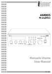
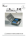
1
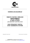
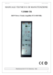
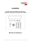
Next
R
Wi D M X
Wireless DMX 512 TRANSCEIVER
I
MANUALE DI INSTALLAZIONE ED USO
Complimenti per l’acquisto del Wi DMX. Prima di procedere all’utilizzo di
questo prodotto è necessario leggere attentamente il presente libretto di
istruzioni per effettuarne una corretta installazione e per sfruttarne al
meglio le potenzialità.
PANNELLO FRONTALE
I
Next
1
Wi D M X
2
1
2
3
DMX 512 ch 40hZ
4
MODE
6
SET
9VDC
7
IN
5
DM
OU
T
X 5
12
IN
M.
TER OFF
ON
1
Visualizza lo stato di trasmissione/ricezione del canale 1
2
Visualizza lo stato di trasmissione/ricezione del canale 2
3
Display LCD, visualizza le informazioni relative al funzionamento del Wi DMX
4
Tasto MODE
5
Tasto SET
6
Tasto DOWN
7
Tasto UP
INDICE
Impostazione dell’apparecchiatura
1.1 Disimballaggio dell’apparecchiatura
1.2 Accessori in dotazione e documentazione relativa
Descrizione pannello laterlale e installazione
2.1
2.2
2.3
2.4
Descrizione pannello laterale
Costruzione del cavo segnale DMX 512
Connessione ingresso di alimentazione
Connessione dell’alimentatore alla rete elettrica
Settaggio iniziale
3.1 Impostazione dei modi di funzionamento
Utilizzo dell’apparecchiatura - modi di funzionamento
4.1
4.2
4.3
4.4
4.5
4.6
Modo di funzionamento TRANSMITTER
Configurazione del Tx1
Stato del LED 1
Configurazione del Tx2
Stato del LED 2
Abbinamento del ricevitore (PAIRING)
5.1
5.2
5.3
5.4
5.5
5.6
5.7
Modo di funzionamento RECEIVER
Funzionamento del Rx1
Stato del LED 1
Funzionamento del Rx2
Stato del LED 2
Abbinamento al trasmettitore (GET PAIRING)
Abbinamento al trasmettitore (GET PAIRING) CON Wi D PEN
6.1
6.2
6.3
6.4
6.5
6.6
6.7
6.8
Modo di funzionamento EXTENDER
Configurazione del Tx1
Stato del LED 1
Configurazione del Rx2
Stato del LED 2
Abbinamento del ricevitore (PAIRING)
Abbinamento al trasmettitore (GET PAIRING)
Abbinamento al trasmettitore (GET PAIRING) CON Wi D PEN
7.1 Modo di funzionamento TX BACKUP
1.1
DISIMBALLAGGIO DELL’APPARECCHIATURA
Aprire la scatola, togliere l’alimentatore e la documentazione.
Togliere l’apparecchiatura dalla scatola come riportato nella figura sottostante.
1.2
ACCESSORI IN DOTAZIONE E DOCUMENTAZIONE RELATIVA
Controllare il contenuto delle confezioni.
Se uno dei seguenti elementi contenuti nelle confezioni dovesse mancare o essere danneggiato, contattare immediatamente il rivenditore.
•
•
•
•
•
•
Wi DMX
Manuale di installazione ed uso.
Garanzia
Alimentatore mod.1814807
1 connettore XLR 3/5 poli maschio
1 connettore XLR 3/5 poli femmina
Leggere attentamente le seguenti avvertenze prima di iniziare l’installazione.
• Apparecchio non per uso domestico.
• Leggete il presente manuale con attenzione e seguite queste precauzioni prima di
operare con il transceiver.
• Fate estrema attenzione a non versare liquidi sul transceiver, oppure di operare in
condizioni di eccessiva umidità.
• Evitate di installare il transceiver vicino a fonti di calore eccessivo, di esporlo a irradiazione solare diretta e di posizionarlo senza alcuna protezione in ambienti polverosi.
• Per la pulizia non usate solventi tipo acetone o alcool, che danneggerebbero la finitura
esterna e le serigrafie dei pannelli.
• In caso di cattivo funzionamento di qualsiasi dispositivo del sistema affidatevi al più vicino
centro di assistenza o ad un centro specializzato, evitando di provvedere personalmente.
2.1
DESCRIZIONE PANNELLO LATERALE
1
2
5
1
5
1
4
2
4
2
3
3
3
1
USCITA segnale DMX 512 con connettore cannon 3/5 poli.
2
INGRESSO segnale DMX 512 con connettore cannon 3/5 poli.
3
TERMINATORE DMX
2.2
COSTRUZIONE DEL CAVO SEGNALE DMX 512
L’ingresso/uscita DMX 512 del Wi DMX è realizzato con connettori standard XLR 5
Pin o XLR 3 Pin secondo le versioni.
Il collegamento deve essere effettuato con cavo schermato di queste caratteristiche:
-
2 conduttori più la schermatura
impedenza di 120 ohm
bassa capacità
velocità trasmissione max. 250 Kbaud.
Per il collegamento fare riferimento alla figura sottostante
XLR 5-pin
XLR 3-pin
5
1
4
2
3
Common
DMX DMX +
2
1
3
Common
DMX DMX +
ATTENZIONE: Non collegare mai la calza del cavo con la terra dell’impianto elettrico,
potrebbero verificarsi anomalie nel funzionamento dell’apparecchio.
2.3
CONNESSIONE INGRESSO DI ALIMENTAZIONE
4
Inserire fino in fondo il connettore dell’alimentatore nell’apposito ingresso di alimentazione 4
Per disinserirlo è sufficiente estrarlo dolcemente.
ATTENZIONE: Non usare mai alimentatori diversi da quello fornito, potrebbero verificarsi seri danni alla circuitazione interna.
2.4
CONNESSIONE DELL’ALIMENTATORE ALLA RETE ELETTRICA
ASSICURARSI CHE LA TENSIONE E FREQUENZA DI RETE COINCIDANO CON
QUELLI RIPORTATI NELLA TARGHETTA DELL’ALIMENTATORE.
L’alimentatore fornito è del tipo a spina, quindi è sufficiente inserirlo nella presa
elettrica.
Appena inserita la spina e collegato il connettore
al W I D M X , il display lcd appare come in
(Fig.1), nel caso ciò non si verifichi, controllare
la presenza di tensione nella presa elettrica, il
collegamento alimentatore-centralina e alimentatore-presa elettrica.
Next
Nel caso il problema continuasse consultare il rivenditore.
WIRELESS
Fig. 1
3.1
IMPOSTAZIONE DEI MODI DI FUNZIONAMENTO
WI DMX all’ acquisto e’ settato per il funzionamento come TRANSMITTER
QUALUNQUE SIA LA CONFIGURAZIONE E’ NECESSARIO ESEGUIRE LE OPERAZIONI DI
ABBINAMENTO (PAIRING) DESCRITTE NEI RELATIVI CAPITOLI DI QUESTO MANUALE
Questa procedura permette di passare fra i modi di funzionamento TRANSMITTER - RECEIVER - EXTENDER - TX BACKUP.
SET
-Spegnere l’apparecchio scollegando il connettore dell’alimentatore.
-Tenere premuto il tasto SET (Fig.2) e contemporaneamente
accendere l’apparecchio inserendo il connettore dell’alimentatore.
Fig. 2
CFG : TRANSMITTER
Il display lcd appare come in (Fig.3).
Per cambiare il modo di funzionamento
utilizzare i tasti UP/DOWN.
A selezione avvenuta confermare tramite il tasto SET (Fig.2).
4.1
Fig. 3
MODO DI FUNZIONAMENTO TRANSMITTER
Questo modo di funzionamento permette di trasmettere il segnale DMX 512 proveniente da un controller ai ricevitori abbinati, attraverso due canali di trasmissione.
Il collegamento deve essere effettuato come in (Fig.4)
Wi DMX rileva il segnale DMX 512 appena si inserisce
il connettore XLR e visualizza il numero di canali generati dal controller (Fig.5); in assenza di segnale il
display appare come in (Fig.6).
5
4
3
1
5
2
4
1
3
2
DMX proveniente
dal controller
DMX per altri
apparecchi
dmx : 512 ch, 40 hz
Fig. 5
Fig. 4
dmx : <<no data>>
Fig. 6
4.2
CONFIGURAZIONE DEL TX1
Questa funzione permette di impostare l’intervallo di canali DMX da trasmettere ai ricevitori abbinati sulla banda 1 (LED ROSSO) e il canale RADIO
da utilizzare tra i dieci disponibili (da 0R a 9R).
Tramite il tasto MODE (Fig.7) arrivare alla schermata come in (Fig.8).
MODE
Per cambiare le impostazioni mantenere premuto il tasto SET (Fig.9)
fino a quando il primo valore inizia a lampeggiare (Fig.10).
Per modificare il valore usare i tasti UP/DOWN (Fig.11).
Per spostarsi al valore successivo utilizzare il tasto MODE (Fig.7).
Fig. 7
A modifica effettuata confermare tramite il tasto SET (Fig.9)
TX1 : 1 - 48 C : 0R
SET
Fig. 8
TX1 : 1 48 C : 0R
Fig. 9
Fig. 11
Fig. 10
L’intervallo dei canali DMX da trasmettere deve corrispondere ai canali
utilizzati dai proiettori collegati ai ricevitori abbinati sulla banda 1.
Si consiglia di impostare tali proiettori su indirizzi DMX consecutivi.
N.B.: Se si riscontrano problemi di trasmissione o si utilizzano nello stesso
ambiente diversi Wi DMX, si consiglia di cambiare canale Radio.
Quando viene modificato il canale Radio, i ricevitori vanno in autoricerca fino a
quando non rilevano il nuovo canale Radio.
4.3
STATO DEL LED 1 (ROSSO)
Lampeggio lento : Trasmissione OK con assenza di segnale DMX 512.
Acceso : Trasmissione OK con presenza di segnale DMX 512.
4.4
CONFIGURAZIONE DEL TX2
Questa funzione permette di impostare l’intervallo di canali DMX da trasmettere ai ricevitori abbinati sulla banda 2 (LED VERDE) e il canale RADIO
da utilizzare tra i dieci disponibili (da 0G a 9G).
Tramite il tasto MODE (Fig.12) arrivare alla schermata come in
(Fig.13).
MODE
Per cambiare le impostazioni mantenere premuto il tasto SET (Fig.14)
fino a quando il primo valore inizia a lampeggiare (Fig.15).
Per modificare il valore usare i tasti UP/DOWN (Fig.16).
Fig. 12
Per spostarsi al valore successivo utilizzare il tasto MODE (Fig.12).
A modifica effettuata confermare tramite il tasto SET (Fig.14)
TX2 : 49 - 128 C : 0G
SET
Fig. 13
TX2 : 49 128 C : 0G
Fig. 14
Fig. 16
Fig. 15
L’intervallo dei canali DMX da trasmettere deve corrispondere ai canali
utilizzati dai proiettori collegati ai ricevitori abbinati sulla banda 2.
Si consiglia di impostare tali proiettori su indirizzi DMX consecutivi.
N.B.: Se si riscontrano problemi di trasmissione o si utilizzano nello stesso
ambiente diversi Wi DMX, si consiglia di cambiare canale Radio.
Quando viene modificato il canale Radio, i ricevitori vanno in autoricerca fino a
quando non rilevano il nuovo canale Radio.
4.5
STATO DEL LED 2 (VERDE)
Lampeggio lento : Trasmissione OK con assenza di segnale DMX 512.
Acceso : Trasmissione OK con presenza di segnale DMX 512.
4.6
ABBINAMENTO DEL RICEVITORE (PAIRING)
Questa funzione permette di abbinare il ricevitore Wi D Pen al trasmettitore
Wi DMX, in modo da evitare interazioni con altri apparecchi dello stesso tipo.
Tramite il tasto MODE (Fig.17) arrivare alla schermata come in (Fig.18).
Inserire il ricevitore Wi D Pen nell’ ingresso di segnale DMX IN
del Wi DMX (Fig.20/1) senza collegare il suo alimentatore.
MODE
Mantenere premuto il tasto SET (Fig.19) fino quando compare la
scritta come in (Fig.20).
PAIR RECEIVER
Fig. 18
Fig. 17
SET
PAIRing : wait...
Fig. 20
Fig. 19
Fig. 20/1
Dopo qualche secondo viene dato un esito dell’abbinamento, ad esito come in (Fig.21)
l’abbinamento è stato effettuato con successo.
Se l’abbinamento non è riuscito appare il messaggio di (Fig.22).
PAIRing : <ok!>
Fig. 21
PAIRing : failed!
Fig. 22
5.1
MODO DI FUNZIONAMENTO RECEIVER
Questo modo di funzionamento permette di Ricevere il segnale DMX 512 proveniente da un trasmettitore e fornirlo ai proiettori collegati.
Il collegamento deve essere effettuato come
in (Fig.23).
In questa modalità si consiglia di portare il
terminatore su ON
Wi DMX rileva il segnale Radio e visualizza il
numero di canali generati (Fig.24); in assenza
di segnale Radio o DMX il display appare
come in (Fig.25).
dmx : 512 ch, 40 hz
Fig. 24
Fig. 23
5
1
5
1
4
2
4
2
3
DMX verso i
proiettori
3
Terminatore
dmx : <<no data>>
Fig. 25
5.2
FUNZIONAMENTO DEL RX1
La funzione permette di visualizzare lo stato del ricevitore della banda 1.
Tramite il tasto MODE (Fig.26) arrivare alla schermata come in
(Fig.27).
rX1 : 48ch C : 0R
Ricezione OK
Fig. 27
rX1 : no data C : 0R
Ricezione OK senza segnale DMX
Fig. 27
rX1 : searching...
Ricerca canale Radio
Fig. 27
5.3
STATO DEL LED 1 (ROSSO)
Lampeggio lento : Ricezione OK con assenza di segnale DMX 512.
Lampeggio veloce : Autoricerca canale.
Acceso : Ricezione OK con presenza di segnale DMX 512.
MODE
Fig. 26
5.4
FUNZIONAMENTO DEL RX2
La funzione permette di visualizzare lo stato del ricevitore della banda 2.
Tramite il tasto MODE (Fig.28) arrivare alla schermata come in
(Fig.29).
rX2 : 128ch C : 0g
Ricezione OK
Fig. 29
rX2 : no data C : 0g
Ricezione OK senza segnale DMX
Fig. 29
rX2 : searching...
Ricerca canale Radio
Fig. 29
5.5
STATO DEL LED 2 (VERDE)
Lampeggio lento : Ricezione OK con assenza di segnale DMX 512.
Lampeggio veloce : Autoricerca canale.
Acceso : Ricezione OK con presenza di segnale DMX 512.
MODE
Fig. 28
5.6
ABBINAMENTO AL TRASMETTITORE (GET PAIRING)
Questa funzione permette di abbinare il Wi DMX impostato come ricevitore a
un Wi DMX trasmettitore, in modo da evitare interazioni con altri apparecchi
dello stesso tipo. Per effettuare questa operazione è necessario un cavo di
segnale collegato tra i due apparecchi.
MODE
Rimuovere qualsiasi collegamento presente sui connettori DMX e collegare il cavo di segnale DMX tra i due apparecchi.
Nell’ apparecchio Wi DMX RICEVITORE, tramite il tasto MODE (Fig.29)
arrivare alla schermata come in (Fig.30).
Fig. 29
Nell’ apparecchio Wi DMX TRASMETTITORE, tramite il tasto MODE (Fig.29) arrivare alla
schermata come in (Fig.31).
Nell’ apparecchio Wi DMX RICEVITORE mantenere premuto il tasto SET
(Fig.32) fino quando compare la scritta come in (Fig.33).
Nell’ apparecchio Wi DMX TRASMETTITORE mantenere premuto il tasto
SET (Fig.32) fino quando compare la scritta come in (Fig.34).
SET
Fig. 32
Wi DMX RICEVITORE
Wi DMX TRASMETTITORE
get pairing
PAIR RECEIVER
Fig. 30
PAIRing : reading
Fig. 31
PAIRing : wait...
Fig. 33
Fig. 34
Dopo qualche secondo viene dato un esito dell’abbinamento, ad esito come in (Fig.35)
su entrambi gli apparecchi l’abbinamento è stato effettuato con successo.
Se l’abbinamento non è riuscito appare il messaggio di (Fig.36).
PAIRing : <ok!>
Fig. 35
PAIRing : failed!
Fig. 36
5.7
ABBINAMENTO AL TRASMETTITORE (GET PAIRING) CON WI D PEN
Questa funzione permette di abbinare il Wi DMX impostato come ricevitore a
un Wi DMX trasmettitore.
Per effettuare questa operazione è necessario Wi D PEN già associata al Wi
DMX trasmettitore (v.par.4.6)
Tramite il tasto MODE (Fig.37) arrivare alla schermata come in (Fig.38).
Inserire il ricevitore Wi D Pen nell’ ingresso di segnale DMX
(senza collegare il suo alimentatore).
Mantenere premuto il tasto SET (Fig.39) fino quando compare la
scritta come in (Fig.40).
get pairing
MODE
Fig. 37
SET
Fig. 38
PAIRing : reading
Fig. 39
Fig. 40
Dopo qualche secondo viene dato un esito dell’abbinamento, ad esito come in (Fig.41)
l’abbinamento è stato effettuato con successo.
Se l’abbinamento non è riuscito appare il messaggio di (Fig.42).
PAIRing : <ok!>
Fig. 41
PAIRing : failed!
Fig. 42
6.1
MODO DI FUNZIONAMENTO EXTENDER
Questo modo di funzionamento permette di Ricevere il segnale DMX 512 proveniente da un trasmettitore, fornirlo ai proiettori collegati e ritrasmetterlo ad altri apparecchi ricevitori.
Il collegamento deve essere effettuato come
in (Fig.43)
In questa modalità si consiglia di portare il
terminatore su ON
Wi DMX rileva il segnale Radio e visualizza il
numero di canali generati (Fig.44); in assenza
di segnale Radio o DMX il display appare
come in (Fig.45).
dmx : 512 ch, 40 hz
Fig. 44
Fig. 43
5
4
3
1
5
2
4
DMX verso i
proiettori
1
3
2
Terminatore
dmx : <<no data>>
Fig. 45
6.2
GB CONFIGURAZIONE DEL TX1
I
Questa funzione permette di impostare la banda e il canale RADIO da utilizzare tra i venti disponibili (da 0R a 9R e da 0G a 9G).
Tramite il tasto MODE (Fig.46) arrivare alla schermata come in (Fig.47).
MODE
Per cambiare le impostazioni mantenere premuto il tasto SET (Fig.48)
fino a quando il valore inizia a lampeggiare (Fig.49).
Per modificare il valore usare i tasti UP/DOWN (Fig.50).
Fig. 46
A modifica effettuata confermare tramite il tasto SET (Fig.48)
TX1 : 48CH C : 0R
SET
Fig. 47
TX1 : 48CH C : 0R
Fig. 48
Fig. 50
Fig. 49
E’ consigliabile non utilizzare lo stesso canale Radio trovato dal ricevitore
N.B.: Se si riscontrano problemi di trasmissione o si utilizzano nello stesso
ambiente diversi Wi DMX, si consiglia di cambiare canale Radio.
Quando viene modificato il canale Radio, i ricevitori vanno in autoricerca fino a
quando non rilevano il nuovo canale Radio.
6.3
STATO DEL LED 1
Lampeggio lento : Trasmissione OK con assenza di segnale DMX 512.
Acceso : Trasmissione OK con presenza di segnale DMX 512.
N.B.: Se si utilizza un canale Radio tra 0R e 9R il led è Rosso.
Se si utilizza un canale Radio tra 0G e 9G il led è Verde.
6.4
CONFIGURAZIONE
DEL RX2
F
La funzione permette di visualizzare lo stato del ricevitore e modificare la
banda di ricezione.
Tramite il tasto MODE (Fig.51) arrivare alla schermata come in (Fig.52).
Per cambiare la banda di ricezione mantenere premuto il tasto SET
(Fig.53) fino a quando il valore cambia (Fig.54).
rX2 : 128ch C : 0g
MODE
Ricezione OK
Fig. 52
rX2 : no data C : 0g
Fig. 51
Ricezione OK
senza segnale DMX
SET
Fig. 52
rX2 : searching...
Ricerca canale Radio
Fig. 53
Fig. 52
rX2 : 128ch C : 0r
Banda Radio modificata
Fig. 54
6.5
STATO DEL LED 2
Lampeggio lento : Ricezione OK con assenza di segnale DMX 512.
Lampeggio veloce : Autoricerca canale.
Acceso : Ricezione OK con presenza di segnale DMX 512.
N.B.: Se si utilizza un canale Radio tra 0R e 9R il led è Rosso.
Se si utilizza un canale Radio tra 0G e 9G il led è Verde.
6.6
ABBINAMENTO DEL RICEVITORE (PAIRING)
Questa funzione permette di abbinare il ricevitore Wi D Pen al TX1 dell’
Extender Wi DMX.
Per le operazioni da effettuare (v.par.4.6)
6.7
ABBINAMENTO AL TRASMETTITORE (GET PAIRING)
Questa funzione permette di abbinare il RX2 di Wi DMX impostato come
Extender a un Wi DMX trasmettitore.
Per le operazioni da effettuare (v.par.5.6)
6.8
ABBINAMENTO AL TRASMETTITORE (GET PAIRING) CON WI DPEN
Questa funzione permette di abbinare il RX2 di Wi DMX impostato come
Extender a un Wi DMX trasmettitore utilizzando Wi D PEN
Per le operazioni da effettuare (v.par.5.7)
7.1 MODO DI FUNZIONAMENTO TX BACKUP
Il modo di funzionamento TX BACKUP si usa per un immediato backup del Wi DMX in
caso di guasto.
Questo modo operativo è lo stesso del TRASMETTITORE, ma i dati sono copiati da un
altro transmettitore.
In caso di guasto del trasmettitore, l’ unità settata come TX BACKUP può generare lo
stesso segnale dell’originale, i ricevitori funzioneranno senza dover rifare la procedura
di PAIRING.
Si raccomanda di non usare Wi DMX trasmettitore e Wi DMX backup insieme.
Come impostare il modo di funzionamento TX BACKUP:
Spegnere l’apparecchio scollegando il connettore dell’alimentatore.
Tenere premuto il tasto SET (Fig.55) e contemporaneamente accendere l’apparecchio inserendo il connettore
dell’alimentatore.
Il display lcd appare come in (Fig.57).
Cercare TX BACKUP tramite i tasti UP/DOWN.
Confermare tramite il tasto SET (Fig.55).
Come CLONARE un trasmettitore>
Nel modo di funzionamento TX BACKUP, WiDMX può clonare fino a 10 trasmettitori.
Prima di clonare un trasmettitore, si deve selezionare dove salvare i dati:
SET
Fig. 55
MODE
Fig. 56
CFG : TRANSMITTER
Fig. 57
select clone : TA
Tramite il tasto MODE (fig.56), cercare la scritta
SELECT CLONE: Ta come in (fig.58)
Tenere premuto il tasto SET per più di 2 secondi, Ta inizia a lampeggiare
Tramite i tasti UP/DOWN, selezionare le opzioni disponibili da Ta a Tj
Confermare tramite il tasto SET
Fig. 58
Da questo momento é possibile clonare Wi-DMX.
Si può clonare sia con il trasmettitore originale oppure con il ricevitore Wi-DPen che
era stata associato con il trasmettitore originale.
Con il trasmettitore originale Wi-DMX:
Rimuovere qualsiasi collegamento presente sui connettori DMX
Collegare il cavo di segnale DMX tra i due apparecchi.
Nell’ apparecchio Wi DMX TRASMETTITORE, tramite il tasto MODE (Fig.56) cercare la schermata
PAIR RECEIVER come in (Fig.60).
Nell’ apparecchio Wi DMX TX BACKUP, tramite il tasto MODE (Fig.56) cercare la schermata
CLONE PAIRING come in (Fig.59), mantenere premuto il tasto SET(Fig.55) fino quando compare la scritta PAIRING:READING...(fig.61)
Nell’ apparecchio Wi DMX TRASMETTITORE mantenere premuto il tasto SET (Fig.55) fino quando
compare la scritta PAIRING: WAIT... (Fig.62).
Dopo qualche secondo viene dato un esito dell’abbinamento, ad esito come in (Fig.63) su entrambi gli apparecchi l’abbinamento è stato effettuato con successo.
Se l’abbinamento non è riuscito appare il messaggio di (Fig.64).
Con il ricevitore Wi-DPen (si clona un Trasmettitore sempre anche se guasto):
Rimuovere qualsiasi collegamento presente sui connettori DMX del Wi-DMX TX BACKUP
Inserire il ricevitore Wi D Pen nell’ ingresso di segnale DMX IN del Wi DMX vedi
(Fig.20/1 par 4.6) senza collegare il suo alimentatore.
Nell’ apparecchio Wi DMX TX BACKUP, tramite il tasto MODE (Fig.56) cercare la schermata CLONE
PAIRING come in (Fig.59), mantenere premuto il tasto SET(Fig.55) fino quando compare la scritta PAIRING:READING...(fig.61)
Wi DMX TX BACKUP
Wi DMX TRANSMITTER
clone pairing
PAIR RECEIVER
Fig. 59
PAIRing : reading
Fig. 60
PAIRing : wait...
Fig. 61
Fig. 62
Dopo qualche secondo viene dato un esito dell’abbinamento, ad esito come in (Fig.63) su entrambi gli apparecchi l’abbinamento è stato effettuato con successo.
Se l’abbinamento non è riuscito appare il messaggio di (Fig.64).
PAIRing : <ok!>
Fig. 63
PAIRing : failed!
Fig. 64
Dopo aver clonato il trasmettitore, si possono impostare i canali radio T_1 e T_2 DMX, in modo
che TX BACKUP sarà pronto per l’uso.
Per clonare un’ altro trasmettitore ripetere le operazioni sopra descritte.
CARATTERISTICHE TECNICHE Wi DMX
Caratteristiche tecniche segnale:
Tipo di segnale di uscita: DMX 512/1990
Tipo di segnale d’ ingresso: DMX 512/1990
Connettore di uscita: Cannon 3 poli/5 poli femmina
Connettore d’ ingresso: Cannon 3 poli/5 poli maschio
N° max proiettori collegabili all’uscita DMX: 32
Caratteristiche tecniche Radio:
Banda di frequeza: 2,4 GHz - 2,483 GHz (ISM)
N° canali utilizzati: 20
Copertura Radio: 1000 metri in campo aperto
Condizioni climatiche di utilizzo:
Umidità: 35% ÷ 80%
Temperatura: 5° ÷ 50 °C
Alimentazione:
Tensione / corrente: 9 Vdc / 800 mA
Dimensioni e peso:
Dimensioni (L x H x P) / Peso: 113 x 45 x 224 mm / 0,9 Kg.
0122
!
FCC ID: R8KUGWR2USXXXX
Canadian Cert No IC: 5125A-UGWR2US
CODEM MUSIC S.r.l. - Via G.Pierini, 13 - 61100 PESARO - ITALY
Tel. +39 0721 204357 - Fax +39 0721 203554
http://www.wi-dmx.com - E-mail: [email protected]
Tutti i diritti sono riservati e questo documento non può essere copiato, fotocopiato, riprodotto per intero o in parte senza il consenso scritto della CODEM MUSIC S.r.l.
Non si assume alcuna responsabilità per eventuali inesattezze o errori.
La CODEM MUSIC S.r.l. si riserva il diritto di apportare senza preavviso cambiamenti, modifiche estetiche o funzionali al prodotto.
La CODEM MUSIC S.r.l. non assume alcuna responsabilità sull’uso o sull’applicazione di questo prodotto.
I
Next
R
Wi D M X
Wireless DMX 512 TRANSCEIVER
GB
USER’S MANUAL
We congratulate you on your purchase of Wi DMX.
Before you proceed using this product, read this user’s manual carefully, as
it gives important information on safety, use and maintenance .
GB
FRONT PANEL
Next
1
Wi D M X
2
1
2
3
DMX 512 ch 40hZ
4
MODE
6
SET
9VDC
7
IN
5
DM
OU
T
X 5
12
IN
M.
TER OFF
ON
1
Shows the state of transmission/receipt of the channel 1
2
Shows the state of transmission/receipt of the channel 2
3
LCD display, it shows all the informations on the Wi DMX functions.
4
MODE key
5
SET key
6
DOWN key
7
UP key
INDEX
Setting of the equipment
1.1 Unpack WI DMX
1.2 Acessories and documentation provided with the equipment
Description of the side panel and installation
2.1
2.2
2.3
2.4
Description of the side panel
Making a DMX 512 signal cable
Input connection for power supply
Connection of the ac-adapter to main AC
Initial setting
3.1 Setting of the operating mode
Use of the equipment - operating modes
4.1
4.2
4.3
4.4
4.5
4.6
TRANSMITTER mode
Setting of Tx1
LED 1 function
Setting of Tx2
LED 2 function
Receiver PAIRING
5.1
5.2
5.3
5.4
5.5
5.6
5.7
RECEIVER mode
State of Rx1
LED 1 function
State of Rx2
LED 2 function
Pairing with Transmitter (GET PAIRING)
Pairing with Transmitter (GET PAIRING) using Wi D PEN
6.1
6.2
6.3
6.4
6.5
6.6
6.7
6.8
EXTENDER mode
Setting of Tx1
LED 1 function
Setting of Rx2
LED 2 function
Receiver PAIRING
Pairing with Transmitter (GET PAIRING)
Pairing with Transmitter (GET PAIRING) using Wi D PEN
7.1 TX BACKUP mode
1.1
UNPACK WI-DMX
Open the box; Remove the ac-adapter and the documentation.
Take the equipment out of the box as shown in the picture below.
1.2
ACESSORIES AND DOCUMENTATION PROVIDED WITH THE EQUIPMENT
Verify the contents of the packing.
If one of the following parts of the packing is missing or damaged, please,
contact your dealer immediately.
•
•
•
•
•
•
Wi DMX
User’s manual.
Warranty
Ac-adapter mod.1814807
1 XLR 3/5 P male connector
1 XLR 3/5 P female connector
Read the following warnings before beginning installation.
• This unit is not intended for home use.
• Read this manual thoroughly and observe the following precautions before working
with the Wi DMX.
• Take care not to spill liquids on to the controller and do not use it in excessively humid
conditions.
• Do not install Wi DMX near heat sources or expose it to direct sunlight and do not
install in dusty environments without suitable protection.
• Do not use Wi DMX unless the ac-adapter cable and plug are in perfect condition
(replace or repair if necessary).
• Do not use solvents such as acetone or alcohol to clean the controller or the finish
and panel lettering will be damaged.
• If a fault occurs, consult your nearest service centre or a specialized light equipment
repair service. Do not attempt to repair the controller yourself.
2.1
DESCRIPTION OF THE SIDE PANEL
1
2
5
1
5
1
4
2
4
2
3
3
3
1
Standard DMX 512 signal OUTPUT with a 3/5-pole cannon connector.
2
Standard DMX 512 signal INPUT with a 3/5-pole cannon connector.
3
DMX TERMINATOR
2.2
MAKING A DMX 512 SIGNAL CABLE
Wi DMX has a DMX 512 input/output that uses standard XLR 5-pin or XLR 3-pin
connectors.
The connection must be put into practice with shielded cable by these characteristics:
-
2 conductors + shield
120 Ohm impedance
low capacity
maximum transmission rate 250 Kbaud.
For the connection refer to the underlying picture
XLR 5-pin
XLR 3-pin
5
1
4
2
3
Common
DMX DMX +
2
1
3
Common
DMX DMX +
ATTENTION: the shield of the cable must never be connected to the ground of the
electrical system as this could cause faults during the working of the Wi DMX.
2.3
INPUT CONNECTION FOR POWER SUPPLY
4
Plug the connector of the ac-adapter completly in the power input
To disconnect it, extract gently.
4
ATTENTION: do not use ac-adapters different from the one supplied, it
could cause serious damages at the internal circuitation.
2.4
CONNECTION OF THE AC-ADAPTER TO THE MAIN AC
MAKE SURE THAT VOLTAGE AND POWER FREQUENCY CORRESPOND TO
WHAT IS REPORTED ON THE AC ADAPTER PLATE.
The supplied ac-adapter has a plug, therefore you should only plug it in the
socket.
When Wi DMX is powered, on display
appears as in (Fig.1),if this condition is not
true, please check if there is power in the
electric socket or check the connection
between ac-adapter/controller and ac-adapter/electric socket.
If the problem persist, please consult your dealer.
Next
WIRELESS
Fig. 1
3.1
SETTING OF THE OPERATING MODE
The Wi DMX factory default mode is TRANSMITTER
REGARDLESS OF THE MODE, YOU MUST EXECUTE THE PAIRING OPERATIONS
EXPLAINED IN THE RELATIVE CHAPTERS OF THIS MANUAL
This procedure allows to change between TRANSMITTER RECEIVER - EXTENDER - BACKUP mode of operation.
SET
-Power down the Wi DMX.
-While holding down SET key (Fig.2), Power up the Wi DMX.
Fig. 2
On display appears as in (Fig.3).
Use UP/DOWN keys to change operating
mode.
Confirm with SET key (Fig.2).
4.1
CFG : TRANSMITTER
Fig. 3
TRANSMITTER MODE
This operation mode allows you to transmit the DMX 512 signal coming from a controller to the paired receivers, through two channels of transmission.
The connection must be like in (Fig.4)
Wi DMX analyzes the DMX 512 signal as soon as the
XLR connector is inserted and shows the number of
channels generated from the controller (Fig.5);
in absence of signal the display appears like in (Fig.6).
5
4
3
1
5
2
4
1
3
2
DMX coming
from controller
DMX to other
projectors
dmx : 512 ch, 40 hz
Fig. 5
Fig. 4
dmx : <<no data>>
Fig. 6
4.2
SETTING OF TX1
This function allows to set the range of DMX channels to transmit on band
1 (RED LED) to the paired receivers and the RADIO channel to use, among
the ten available (from 0R to 9R).
With MODE key (Fig.7) find the text like in (Fig.8).
MODE
To change the setting hold SET key (Fig.9) until the first value starts
blinking (Fig.10).
Use UP/DOWN keys to change the value (Fig.11).
Fig. 7
Use MODE key to move to the next value (Fig.7).
When finished, confirm with SET key (Fig.9)
TX1 : 1 - 48 C : 0R
SET
Fig. 8
TX1 : 1 48 C : 0R
Fig. 9
Fig. 11
Fig. 10
The range of DMX channels to transmit must correspond to the channels used by the projectors connected to the paired receivers on band 1.
You should set such projectors on consecutive DMX addresses.
N.B.: If you get problem of transmission, try changing the Radio channel.
When Radio channel is modified, receivers start searching until they find the
new Radio channel.
4.3
LED 1 FUNCTION (RED)
Slow blinking: Transmitter OK, no DMX 512 signal.
Switched on : Transmitter OK, DMX 512 signal OK.
4.4
SETTING OF TX2
This function allows to set the range of DMX channels to transmit on band
2 (GREEN LED) to the paired receivers and the RADIO channel to use,
among the ten available (from 0G to 9G).
With MODE key (Fig.12) find the text like in (Fig.13).
MODE
To change the setting hold SET key (Fig.14) until the first value starts
blinking (Fig.15).
Use UP/DOWN keys to change the value (Fig.16).
Fig. 12
Use MODE key to move to the next value (Fig.12).
When finished, confirm with SET key (Fig.14)
TX2 : 49 - 128 C : 0G
SET
Fig. 13
TX2 : 49 128 C : 0G
Fig. 14
Fig. 16
Fig. 15
The range of DMX channels to transmit must correspond to the channels used by the projectors connected to the paired receivers on band 2.
You should set such projectors on consecutive DMX addresses.
N.B.: If you get problem of transmission, try changing the Radio channel.
When Radio channel is modified, receivers start searching until they find the
new Radio channel.
4.5
LED 2 FUNCTION (GREEN)
Slow blinking: Transmitter OK, no DMX 512 signal.
Switched on : Transmitter OK, DMX 512 signal OK.
4.6
RECEIVER PAIRING
This function allows to pair the receiver Wi D Pen to the transmitter Wi
DMX, to avoid interactions with other unit of the same type.
With MODE key (Fig.17) find the text like in (Fig.18).
Connect Wi D Pen to the DMX 512 transmitter signal IN
(Fig.20/1) without connecting Wi D Pen ac-adapter.
MODE
Hold SET key (Fig.19) until a writing appears like in (Fig.20).
PAIR RECEIVER
Fig. 18
Fig. 17
SET
PAIRing : wait...
Fig. 20
Fig. 19
Fig. 20/1
After a few seconds a result of the operation is given; if like in (Fig.21) pairing succeeded;
else the message of (Fig.22) appears.
PAIRing : <ok!>
Fig. 21
PAIRing : failed!
Fig. 22
5.1
RECEIVER MODE
This operation mode allows you to receive the DMX 512 signal coming from a Wi
DMX transmitter and provide it to the connected projectors.
The connection must be like in (Fig.23).
In this mode switch terminator to ON
Wi DMX receives the Radio signal and shows
the number of channels generated (Fig.24);
in absence of Radio or DMX signal the display
appears like in(Fig.25).
Fig. 23
5
1
5
1
4
2
4
2
3
DMX to other
projector
dmx : 512 ch, 40 hz
Fig. 24
3
Terminator
dmx : <<no data>>
Fig. 25
5.2
STATE OF RX1
This function allows to visualize the state of the receiver of band 1.
With MODE key (Fig.26) find the text like in (Fig.27).
rX1 : 48ch C : 0R
Reception OK
Fig. 27
rX1 : no data C : 0R
Reception OK no DMX signal
Fig. 27
rX1 : searching...
Radio channel research
Fig. 27
5.3
LED 1 FUNCTION (RED)
Slow blinking: Receiver OK, no DMX 512 signal.
Fast blinking: Channel research.
Switched on : Receiver OK, DMX 512 signal OK.
MODE
Fig. 26
5.4
STATE OF RX2
This function allows to visualize the state of the receiver of band 2.
With MODE key (Fig.28) find the text like in (Fig.29).
rX2 : 128ch C : 0g
Reception OK
Fig. 29
rX2 : no data C : 0g
Reception OK no DMX signal
Fig. 29
rX2 : searching...
Radio channel research
Fig. 29
5.5
LED 2 FUNCTION (GREEN)
Slow blinking: Receiver OK, no DMX 512 signal.
Fast blinking: Channel research.
Switched on : Receiver OK, DMX 512 signal OK.
MODE
Fig. 28
5.6
PAIRING WITH TRANSMITTER (GET PAIRING)
This function allows to pair the Wi DMX set as receiver with a Wi DMX set
as trasmitter, to avoid interactions with other unit of the same type. For
this operation you need a DMX signal cable connected between the two unit.
MODE
Remove any cable on the DMX connectors and connect the DMX
signal cable between the two unit.
On the RECEIVER Wi DMX , with MODE key (Fig.29) find the text like in
(Fig.30).
Fig. 29
On the TRANSMITTER Wi DMX , with MODE key (Fig.29) find the text like
in (Fig.31).
SET
On the RECEIVER Wi DMX hold SET key (Fig.32) until a writing appears
like in (Fig.33).
On the TRANSMITTER Wi DMX hold SET key (Fig.32) until a writing
appears like in (Fig.34).
RECEIVER Wi DMX
Fig. 32
TRANSMITTER Wi DMX
get pairing
PAIR RECEIVER
Fig. 30
PAIRing : reading
Fig. 31
PAIRing : wait...
Fig. 33
Fig. 34
After a few seconds a result of the operation is given; if like in (Fig.35) on both unit, pairing succeeded; else the message of (Fig.36) appears.
PAIRing : <ok!>
Fig. 35
PAIRing : failed!
Fig. 36
5.7
PAIRING WITH TRANSMITTER (GET PAIRING) USING WI D PEN
This function allows to pair the Wi DMX set as receiver with a Wi DMX set
as trasmitter.
For this operation you need a Wi D PEN already paired with the trasmitter
Wi DMX (v.par.4.6)
With MODE key (Fig.37) find the text like in (Fig.38).
MODE
Connect Wi D Pen to the DMX signal input
(without connecting Wi D Pen ac-adapter).
Hold SET key (Fig.39) until a writing appears like in (Fig.40).
Fig. 37
get pairing
SET
Fig. 38
PAIRing : reading
Fig. 39
Fig. 40
After a few seconds a result of the operation is given; if like in (Fig.41) pairing
succeeded; else the message of (Fig.42) appears.
PAIRing : <ok!>
Fig. 41
PAIRing : failed!
Fig. 42
6.1
EXTENDER MODE
This operation mode allows you to receive the DMX 512 signal coming from a Wi
DMX transmitter, provide it to the connected projectors and re-transmit it to other
receiver unit.
The connection must be like in (Fig.43).
In this mode switch terminator to ON
Wi DMX receives the Radio signal and shows
the number of channels generated (Fig.44); in
absence of Radio or DMX signal the display
appears like in (Fig.45).
Fig. 43
5
4
3
1
5
2
4
DMX to other
projector
dmx : 512 ch, 40 hz
Fig. 44
1
3
2
Terminator
dmx : <<no data>>
Fig. 45
6.2
SETTING OF TX1
This function allows to set the range of DMX channels to transmit on band
1 (RED LED) to the paired receivers and the RADIO channel to use, among
the ten available (from 0R to 9R).
With MODE key ( Fig.46) find the text like in ( Fig.47).
MODE
To change the setting hold SET key ( Fig.48) until the value starts
blinking ( Fig.49).
Use UP/DOWN keys to change the value ( Fig.50).
Fig. 46
When finished, confirm with SET key (Fig.48
TX1 : 48ch C : 0R
SET
Fig. 47
TX1 : 48CH C : 0R
Fig. 48
Fig. 50
Fig. 49
It is advisable not to use the same Radio channel found by the receiver.
N.B.: If you get problem of transmission, try changing the Radio channel.
When Radio channel is modified, receivers start searching until they find the
new Radio channel.
6.3
LED 1 FUNCTION
Slow blinking: Transmitter OK, no DMX 512 signal.
Switched on : Transmitter OK, DMX 512 signal OK.
N.B.: If a Radio channel between 0R and 9R is used, the led is Red.
If a Radio channel between 0G and 9G is used, the led is Green.
6.4
SETTING OF F
RX2
This function allows to visualize the state of the receiver and to change the
receiver band.
With MODE key (Fig.51) find the text like in (Fig.52).
To change the receiver band hold SET key (Fig.53) until the value
changes (Fig.54).
rX2 : 128ch C : 0g
MODE
Reception OK
Fig. 52
rX2 : no data C : 0g
Fig. 51
Reception OK
no DMX signal
Fig. 52
rX2 : searching...
SET
Radio channel research
Fig. 53
Fig. 52
rX2 : 128ch C : 0r
Radio band changed
Fig. 54
6.5
LED 2 FUNCTION
Slow blinking: Receiver OK, no DMX 512 signal.
Fast blinking: Channel research.
Switched on : Receiver OK, DMX 512 signal OK.
N.B.: If a Radio channel between 0R and 9R is used, the led is Red.
If a Radio channel between 0G and 9G is used, the led is Green.
6.6
RECEIVER PAIRING
This function allows to pair the receiver Wi D Pen to the TX1 of the Extender
Wi DMX.
Follow the instructions at (v.par.4.6)
6.7
PAIRING WITH TRANSMITTER (GET PAIRING)
This function allows to pair the RX2 of the Extender Wi DMX with a Wi DMX
set as trasmitter.
Follow the instructions at (v.par.5.6)
6.8
PAIRING WITH TRANSMITTER (GET PAIRING) USING WI D PEN
This function allows to pair the RX2 of the Extender Wi DMX with a Wi DMX
set as trasmitter using Wi D PEN.
Follow the instructions at (v.par.5.7)
7.1
TX BACKUP MODE
TX BACKUP mode is intended for use as an immediate backup unit in case of failure
during an event.
This mode works exactly the same as TRANSMITTER mode, but data encoding is
made using the key of another transmitter.
In the event of faiure of the original transmitter, the unit set as TX BACKUP can
generate the same signal as the original and then receiver will work without having to
be paired again.
DO NOT operate the original transmitter and a backup unit togeter as they will interfere each other!
- How to set TX BACKUP mode:
Remove power from Wi-DMX unit
Press and hold SET key (fig.55)
Power up Wi-DMX, then release SET
On display appears as in (fig 57):
Use UP or DOWN key, find TX BACKUP
Press SET key to confirm
- How to 'clone' a transmitter:
When in TX BACKUP mode, Wi-DMX can store
up to 10 different configurations, so it will be
ready to backup one of 10 original transmitters.
Before 'cloning' a transmitter, select where you
want to save its data:
SET
Fig. 55
MODE
Fig. 56
CFG : TRANSMITTER
Fig. 57
select clone : TA
Fig. 58
Using MODE key (fig.56), find SELECT CLONE: Ta on display (fig.58)
Press SET for more than 2 seconds, Ta starts blinking
Using UP or DOWN key, select one of Ta to Tj available settings
Press SET key to confirm
Now you can 'clone' your Wi-DMX transmitter unit. You can do that using the original transmitter or using a Wi-DPen receiver that has previously been paired with it.
With the original Wi-DMX transmitter unit:
Remove any DMX cable from both Wi-DMX (the original TX and the BACKUP)
Connect a DMX cable between the two units
On Wi-DMX TRANSMITTER, using MODE key, find PAIR RECEIVER on display (fig.60)
(don't press SET yet)
On Wi-DMX TX BACKUP, using MODE key, find CLONE PAIRING on display, then
press SET for more than 2 seconds, PAIRING:READING...appears (fig.61)
PAIRING: WAIT...'
On Wi-DMX TRANSMITTER, press SET for more than 2 seconds, 'P
appears (fig.62)
After a few seconds a result of the operation is given; if like in (Fig.63) on both units, pairing succeeded; else the message of (Fig.64) appears.
With a Wi-DPen receiver (this way you can clone a TX even AFTER it is dead...):
Remove any DMX cable from Wi-DMX set as TX BACKUP
Connect Wi-DPen to DMX-IN plug of Wi-DMX
On Wi-DMX TX BACKUP, using MODE key (fig.56), find 'CLONE PAIRING' on display, then press
SET for more than 2 seconds, PAIRING: READING... appears (fig.61)
After a few seconds PAIRING: OK should appear on display (fig.63)
Wi DMX TX BACKUP
Wi DMX TRANSMITTER
clone pairing
PAIR RECEIVER
Fig. 59
PAIRing : reading
Fig. 60
PAIRing : wait...
Fig. 61
Fig. 62
After a few seconds a result of the operation is given; if like in (Fig.63) on both units, pairing succeeded; else the message of (Fig.64) appears.
PAIRing : <ok!>
Fig. 63
PAIRing : failed!
Fig. 64
After 'cloning' the transmitter, you can also set T_1 and T_2 DMX range and radio channel, so
the TX BACKUP will be ready for use.
If you want to clone another unit, repeat from step 1.
Each clone will keep the full setting (DMX range and radio channel), so when needed, just select
the clone and it will be working immediatly
Wi DMX TECHNICAL FEATURES
Technical features: Signal
Output signal: DMX512/ 1990
Input signal: DMX512/ 1990
Output connector: 3/5-pin cannon connector female
Input connector: 3/5-pin cannon connector male
Max number of projectors connected to the DMX output: 32
Technical features: Radio
Frequency range: 2,4 GHz - 2,483 GHz (ISM)
Number of channels: 20
Transmitter range: 1000 meters (3280 ft) open air
Climatic condition for the use
Humidity: 35% ÷ 80%
Temperature: 5 ÷ 50 °C
Power supply
Voltage/current: 9 Vdc / 800 mA
Dimensions and weight
Dimension (W x L x H) / Weight: 113 x 224 x 45 mm / 0,9 Kg.
0122
!
FCC ID: R8KUGWR2USXXXX
Canadian Cert No IC: 5125A-UGWR2US
CODEM MUSIC S.r.l. - Via G.Pierini, 13 - 61100 PESARO - ITALY
Tel. +39 0721 204357 - Fax +39 0721 203554
http://www.wi-dmx.com - E-mail: [email protected]
All rights reserved. No parts of this document can be copied, photocopied or reproduced without the
prior written permission of the CODEM MUSIC s.r.l.
No responibility is taken for possible inaccuracies or mistakes.
The CODEM MUSIC s.r.l. reserves the right to make any alterations or aesthetics changes of this
product that seem necessary at any time and for whatever reason.
The CODEM MUSIC s.r.l. takes no responsibility for the use or for the application of this product.
GB