1
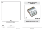
Radioprogrammatore 400W Plus
Radioprogrammer 400W Plus
Récepteur séquentiel 400W Plus
Funkmotorsteuerung 400W Plus
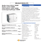
SEL2641R433-P4P
Manuale d’installazione ed uso - Italiano ............Pag. 4
Use and installation Manual - English .................Pag. 7
Notices d’installation et utilisation - Français .....Pag. 10
Bedienungsanleitung - Deutsch ...........................Pag. 13
THE SMART LIVING
?
Misure di sicurezza
Per un perfetto funzionamento dell’apparecchio, si prega di
leggere interamente questo manuale e seguire attentamente
le indicazioni ivi descritte, in quanto l’uso improprio può
danneggiare l’apparecchio
Dichiarazione di Conformità:
Il costruttore Elpro Innotek Spa dichiara che il
radioprogrammatore mod. SEL2641R433-P4P, è conforme
alle Direttive Europee 73/23/CEE, 89/336/CEE e
99/05/CE.
Security measures
For a perfect functioning of the device, read carefully this
manual and follow all the indications, since an inadeguate
use can make damages to the device
Declaration of Conformity:
Elpro Innotek Spa as manufacturer declares that the
following appliances : SEL2641R433-P4P, fullfills the
requirements of the European Directives 73/23/CEE,
89/336/CEE and 99/05/CE.
Mesures de sécurité
Pour un fonctionnement parfait de l’appareil, vous devez
lire complétement les instructions de installation et suivre
estrictement les indications décrites, puisque un maniement
inadéquat peut produire dommage à l’appareil.
Sicherheitsmaßnahmen
Um ein einwanfreies Functionieren des Apparates zu
erhalten, sollten Sie die in der Bedienungsanleitung
enthaltene Anweisungen zur Bedienung und zur Installation
genau durchlesen und befolgen, da eine Nichtbeachtung
derselben starke Schäden am Apparat hervorrufen kann.
?
Déclaration de Conformité:
Elpro Innotek Spa déclare que l’appareil SEL2641R433P4P, est conforme aux exigences essentielles et autres
dispositions des Directives 73/23/CEE, 89/336/CEE et
99/05/CE.
Declaration of Conformity:
Der Funkmotorsteuerung ( typ SEL2641R433-P4P, entspricht
den europäischen Normen 89/336/CEE 73/23/CEE,
99/05/CE, EG Konformitätsbescheinigung.
Presentazione / Introduction / Introduction / Allgemein
4 viti per fissaggio del coperchio
4 screws for cover fixing
4 vis capot
4 Schraube
Coperchio
Cover
Couvercle
Deckel
4 Viti per fissaggio della scatola
4 screws for box fixing
4 vis de fixation
Schraube
Passacavi
Wire leads
Passes-fils
Kabelführung
4 tasselli
4 plugs
4 chevilles
4 Einsatz
Scatola con ricevitore e coperchio di protezione in plexiglass
Receiver box with plexiglas cover
Boîtier avec récepteur et plexiglas de protection
Behälter mit Funkmotorsteuerung
Antenna
Aerial
Fil d’antenne
Antenne
Fig. 1
Pag. 2
Dimensioni d’ingombro / Overall
dimensions Dimensions
Interassi / Drilling distances
Distances de perçage / Spurweiten
52
104
140
115
Fig. 2
128
Fig. 3
Layout
Tasto PR - LED LR
Push-button PR - LED LR
Touche PR - LED LR
Taster PR - LED LR
Tasto PV - LED LV
Push-button PV - LED LV
Touche PV - LED LV
Taster PV - LED LV
Trasformatore di alimentazione
Transformer
Transformateur
Trasformator
PV
PR
LV
LR
1 2 34 5 6
ON ON
ON
Arbeitszeiten OFF
1
2
3
4
5
Fusibile F1 : 3,15A - 250V
Fuse F1 : 3,15A - 250V
Fusible F1 : 3,15A - 250V
Sicherung F1 : 3,15A - 250V
ON
ON
ON
ON
ON
123456
6 sec
12 sec
24 sec
46 sec
96 sec
Mode
Dip-switch 6 vie
Dip-switch
Dip-switch
Dip-switch zur programmierung
Buzzer
F1
P1 N2
230
Ph VN
C
3 M4 5 6 7
C OUV/FERM
O F
8
9 10 11
Led L1 : Contatto NA esterno
Led L1 : NO external command
Led L1 : Contact NO exterieur
Led L1 : Sicherheitsvorrichtung
Morsettiere di I/O
Terminal boards
Bornes
Anschlüsse
S1
S2
S3
S4
S5
ON
ON
ON
ON
ON
=
=
=
=
=
6 sec.
12 sec.
24 sec.
46 sec.
96 sec.
S6 ON = Sequenziale / Sequential mode / sequentiel / sequenziell
S1, S2, .., S5 ON / S6 OFF : Misto / Mixed / Mixte / gemischter Betrieb
S1, S2, .., S6 OFF = Uomo Presente / Man present / homme mort /
Fig. 4
Pag. 3
ITALIANO
4 - INSTALLAZIONE
1 - DESCRIZIONE
Posizionamento
Il ricevitore sequenziale ERONE 400 W Plus è un
radioprogrammatore in grado di pilotare direttamente un motore
asincrono equipaggiato di condensatore di spunto.
Può funzionare esclusivamente con i radiocomandi Erone della
serie 024A , Mini e murali con codifica rolling code come da
tabella seguente:
La scelta della posizione del ricevitore è molto importante per
ottenere un buon funzionamento del sistema.
Devono essere rispettate le seguenti condizioni:
- posizionare il ricevitore lontano da fonti di disturbo quali sistemi
informatici, allarmi o altre emissioni radio.
- la distanza tra due ricevitori deve essere superiore a 1.5 metri.
SERIE
024A
024A
MINI
MURALE
MODELLO
FREQUENZA
CODIFICA
Fissaggio
S2TR2641E2
S2TR2641E4
SETR2641AM2
SETR2641-TM
433.92 MHz
433.92 MHz
433.92 MHz
433.92 MHz
Rolling code
Rolling code
Rolling code
Rolling code
Togliere il coperchio dal ricevitore. Fissare la scatola ad ogni
angolo utilizzando viti e fisher in dotazione o con viti appropriate
alla natura del supporto.
Connessioni
2 - CARATTERISTICHE TECNICHE
Modelli
Tipo ricevitore
Frequenza portante
Frequenza oscillatore locale
Modulazione
Impedenza d'ingresso
Larghezza di canale
Frequenza intermedia
Sensibilità d'ingresso
Emissione dell'oscillatore locale
Tensione di alimentazione
Potenza massima del motore
Capacità di memoria
Codifica
Temperatura di funzionamento
Grado di protezione
Peso
Dimensioni
SEL 2641R433-P4P
Supereterodina
433.92 MHz
6,6128 MHz
AM/ASK
50 Ohm
> 25 KHz
10,7 MHz
-115 dBm
< -57 dBm
230 Vac
400 W
85
Keeloq® Hopping code
-20°/+70°C
IP44
380 gr.
140 x 115 x 52 mm
1- Collegare l'alimentazione ai morsetti corrispondenti (fig. 5):
morsetto 1 = PH fase
morsetto 2 = N neutro
morsetto 6 = terra
Fig. 5
1 2
Ph N
2 - Collegare il motore ai morsetti corrispondenti (fig. 6):
morsetto 3 = C comune
morsetto 4 = O apertura
morsetto 5 = F chiusura
morsetto 7 = terra
collegare il condensatore di rifasamento tra i morsetti 4 e 5.
Fig. 6
3 - FUNZIONALITA'
Sequenziale (o ciclico):
1 Impulso apre
1 Impulso chiude, ferma a tempo o ad impulso.
Misto:
1 impulso apre,
chiusura a uomo presente.
Uomo presente:
apertura e chiusura a contatto permanente (portata ridotta).
Il tempo di lavoro del motore (da 6 a 186sec) è selezionabile
attraverso 5 dip-switches; esso serve anche da sicurezza in caso di
blocco motore, per evitare che questo rimanga sotto tensione.
Possibilità di lavorare in comando locale o in comando generale
per gruppi di serrande; il comando generale è
possibile solo per il funzionamento sequenziale).
Per il comando generale è necessario possedere un trasmettitore a 4
canali della stessa gamma.
È possibile collegare un pulsante esterno o un contatto a chiave
come completamento al radiocomando.
Capacità di memoria del ricevitore : 85 trasmettitori.
Pag. 4
6
3
C
4 5
O F
7
3 -Collegare gli accessori come segue (fig. 7):
- se collegate un'antenna (non in dotazione), collegare la calza al
morsetto 10, ed il centrale al morsetto 11; oppure collegare il filo
d'antenna in dotazione al morsetto 10.
- se collegate un dispositivo di comando (non in dotazione),
collegare il contatto normalmente aperto e impulsivo tra i morsetti 8
e 9;
NOTA2:Il led L1 si accende quando viene attivato il contatto N.A.
del comando esterno.
Led L1
Fig. 7
8
9
10 11
Durante il moto (apertura o chiusura) soltanto il pulsante di arresto
(C) rimane attivo.
5 - PROGRAMMAZIONE
!
Togliere tensione prima di sollevare il plexiglas di
protezione e prima di intervenire sulla morsettiera
Il modo di funzionamento del radioprogrammatore si imposta
facendo uso del dip-switch a 6 vie presente sulla scheda
elettronica ( Fig. 8.)
PV
LR
1 2 34 56
ON
OFF
!
Per essere sicuri di comandare tutti i ricevitori
contemporaneamente, è consigliabile utilizzare il
radiocomando ad una distanza minima ( non
superare i 20 metri )
6 - MEMORIZZAZIONE DEI TRASMETTITORI
PR
LV
Per ottenere l'inversione del moto senza passare per il pulsante di
arresto (C), è necessario attendere la fine del tempo di lavoro.
Fig. 8
ON
123456
Il codice di ogni singolo tasto può essere memorizzato nel
radioprogrammatore in 2 modi diversi:
A / B - Direttamente sul radioprogrammatore mediante pressione
del tasto PR o PV;
C / D - Per autoapprendimento a distanza, mediante i tasti del
radiocomando.
A - Memorizzazione diretta in comando locale PR
1) Premere e tener premuto il pulsante PR : il led LR si accende;
2) Rilasciare il tasto PR ;
NOTA: Il tempo di emissione prolungato causa l'usura più rapida
3) Premere il tasto del trasmettitore che si intende memorizzare : il led
della batteria del radiocomando.
LR si spegne ;
Funzionamento Dip-switch 1-5 Dip-switch 6 4) Ripetere poi l’operazione per ogni tasto del trasmettitore.
Scelta del modo di funzionamento
SEQUENZIALE secondo il
tempo desiderato
( CICLICO )
ON
secondo il
tempo desiderato
OFF
MISTO
A UOMO
PRESENTE
OFF
OFF
Scelta del tempo di lavoro nel modo di
funzionamento sequenziale o misto
B - Memorizzazione diretta in comando generale PV
E' necessario disporre di un trasmettitore a 4 canali della stessa
gamma
Premere e tener premuto il pulsante PV del ricevitore fino
all'accensione del led verde LV;
Entro 4 secondi premere il tasto D del radiocomando da
memorizzare.
Il led LV si spegne ed il relè del motore si eccita per un attimo.
Il tasto D provocherà la chiusura del motore.
La memorizzazione dei rimanenti tasti del radiocomando avviene
automaticamente associando al tasto B l'apertura ed al tasto C
l'arresto.
C - Memorizzazione per autoapprendimento comando
locale PR
Gli switches 1 a 5 posizionati su ON, in funzionamento sequenziale
o misto, permettono di selezionare il tempo di lavoro del motore (lo 1) Premere contemporaneamente i tasti A e B del Tx : i led LR ed
LV si accendono per un attimo ed il buzzer emette un bip;
scadere del tempo di lavoro provoca l'arresto).
2) Premere il tasto A dello stesso TX per 4 sec.: il led LR si accende ed
Switch 1 =
6 secondi
il buzzer emette un bip continuo=Biiiiiiip;
Switch 2 = 12 secondi
3) Premere entro 2 sec. il tasto del Tx da memorizzare: il led LR si
Switch 3 = 24 secondi
spegne.
Switch 4 = 48 secondi
Switch 5 = 96 secondi
Più switches posizionati in ON sommano il tempo di lavoro.
Scelta del tipo di comando
! Comando locale
I trasmettitori memorizzati su PR permettono di lavorare in modo
sequenziale misto o a uomo presente e necessitano di un solo
pulsante del trasmettitore per aprire, chiudere e fermare.
Il comando locale è prioritario sul comando generale.
! Comando generale
E' necessario disporre di un trasmettitore a 4 canali della stessa
gamma.
I trasmettitori memorizzati su PV permettono di lavorare in modo
sequenziale, ma necessitano di tre pulsanti del trasmettitore, un
pulsante (B) per aprire, un pulsante (D) per chiudere, e un
pulsante (C) per l'arresto.
D - Memorizzazione per autoapprendimento comando
generale PV
1) Premere contemporaneamente i tasti A e B del Tx :i led LR ed LV si
accendono per un attimo ed il buzzer emette un bip;
2) Premere il tasto B dello stesso TX per 4 sec.: il led LV lampeggia ed
il buzzer emette un bip intermittente= Bip, Bip, ..,Bip;
3) Premere entro 2 sec. il tasto D del Tx da memorizzare: il led LV si
spegne ed il relè del motore si eccita per un istante.
NOTA 1 : La memorizzazione dei rimanenti tasti del
radiocomando avviene automaticamente associando al tasto B
l'apertura ed al tasto C l'arresto.
Pag. 5
NOTA 2: La memorizzazione per autoapprendimento a distanza
dei TX successivi al primo, in un ricevitore non più vergine, è
consentita solo facendo uso di un TX già memorizzato.
Esempio1 :
Memorizzazione dei tasti A e B di TX2 in comando locale facendo uso
di un tx già memorizzato (TX1)
- Premere i tasti A+B di TX1 (bip) ; Premere A di TX1 per 4 sec.
(Biiiiiiiiiiiip) ; entro 2 sec. premere A di TX2 .
Esempio2 :
Memorizzazione dei tasti B, C e D di TX2 in comando generale
facendo uso di un tx già memorizzato (TX1)
- Premere i tasti A+B di TX1 (bip) ; Premere B di TX1 per 4 sec. (Bip,
bip, .., bip) ; entro 2 sec. premere D di TX2 .
7 - CANCELLAZIONE
Cancellazione completa della memoria
Premere PR fino a quando il led rosso si accende, rilasciare PR poi, di
seguito premere PR e PV contemporaneamente fino a quando i due
led lampeggiano per 3 volte.
In questo modo tutti i codici vengono cancellati dalla memoria.
8 - GESTIONE CONDOMINIALE
Per utilizzare la gestione dei codici, è necessario prendere nota in
quale cella di memoria il codice di ciascun trasmettitore è
memorizzato ed a quale relè è associato.
La gestione dei codici è utile nel caso di memorizzazioni di molti
trasmettitori nel ricevitore, in una installazione condominiale (es.:
100 trasmettitori memorizzabili nelle celle da 1 a 100).
Verifica del numero dei trasmettitori
memorizzati
Sul ricevitore, entrare in modo programmazione premendo PR
finchè LR si accende. Rilasciare PR e ripremere PR per un secondo.
A partire da questo momento, i led lampeggiano formando la
sequenza a 7 bit di cui al numero precedente.
Il totale ricavato con la tabella di corrispondenza indica la quantità
di trasmettitori memorizzati.
Verifica della posizione
trasmettitore in memoria
di
un
codice
Premere sul pulsante del radiocomando che si desidera controllare e
rilasciare. Di seguito premere il pulsante PR del ricevitore per almeno
un secondo. A partire da questo istante i led lampeggiano formando
una sequenza di 7 bit, così come descritto precedentemente.
In base ad essa è possibile risalire alla posizione di memoria del
Sostituzione di un codice in memoria
E' possibile cancellare un codice trasmettitore dalla memoria,
memorizzandone un altro nella stessa posizione.
Per far ciò è necessario conoscere la posizione di memoria del
trasmettitore da sostituire.
Questa operazione può essere fatta seguendo le indicazioni
riportate nel paragrafo precedente "Verifica della posizione di un
codice trasmettitore in memoria".
Una volta nota la posizione di memoria da sostituire, procedere nel
modo seguente:
- Sul ricevitore, premere PR fino a quando il led corrispondente si
accende; rilasciare PR.
- Premere PV per almeno un secondo;
-Comporre di seguito, entro 2 secondi, la sequenza binaria di 7 bit
premendo PR e PV, relativa alla posizione di memoria da sostituire.
Esempio di posizionamento sulla 42 esima cella di memoria:
La posizione della memoria è indicata attraverso una sequenza
binaria a 7 bit.
LR LV LR LV LR LV LR
Per prendere nota della posizione bisogna riferirsi alla tavola di
corrispondenza seguente osservando la posizione nella sequenza
0 2 0
8 0 32 0
del led verde LV:
0 + 2 + 0 + 8 +0 + 32 +0 = 42
codice 7 bit
1
2
3
4
5
6
7
8
16 32 64
LV
corrispondenza
1
2
4
Premere in perciò sequenza:
PR, PV, PR, PV, PR, PV, PR.
A partire da questo momento il led rosso LR si accende a conferma
Bisogna tenere conto soltanto delle accensioni del led verde, dell'ingresso in modo programmazione.
Premere entro 4 secondi il pulsante ( A, B, C o D ) del trasmettitore da
essendo il led rosso uguale allo zero.
memorizzare.
Il led rosso LR si spegne confermando l'avvenuta sostituzione.
ESEMPIO : Lettura dei led per la posizione 37 della memoria:
In questo modo il vecchio codice viene cancellato e il ricevitore
risponde al nuovo codice memorizzato.
1a accensione: led verde
2a
3a
4a
5a
6a
7a
accensione:
accensione:
accensione:
accensione:
accensione:
accensione:
led rosso
led verde
led rosso
led rosso
led verde
led rosso
1
2
3
4
5
6 7
1
2
4
8 16 32 64
1 + 0 + 4 + 0 + 0 + 32 + 0 = 37
Pag. 6
- è possibile utilizzare sempre lo stesso trasmettitore (es.: il
trasmettitore utilizzato per la manutenzione dell'impianto, per
cancellare i codici utenti).
Memoria piena
Quando la memoria è piena, cioè quando le 85 o 100 celle di
memoria ( in relazione al modello utilizzato ) sono occupate, i led
rosso LR e verde LV lampeggiano 3 volte contemporaneamente
quando si entra in programmazione; il led corrispondente al led
sollecitato resta quindi acceso per 4 secondi (modo di
programmazione) al fine di permettere l'eventuale cancellazione di
un trasmettitore già memorizzato (vedi paragrafo precedente).
4 - INSTALLATION
ENGLISH
Positioning
1 - INTRODUCTION
The receiver ERONE 400 W PLus is a radio programmer which
can drive directly an asynchronous 230 Vac AC motor with max
power of 400 W. The operating frequency is 433,92 Mhz and the
and the coding system is Keeloq® Hopping code
SERIES
024A
024A
MINI
WALL TYPE
TYPE
S2TR2641E2
S2TR2641E4
SETR2641AM2
SETR2641-TM
FREQUENCY CODING
433.92
433.92
433.92
433.92
MHz
MHz
MHz
MHz
Rolling
Rolling
Rolling
Rolling
code
code
code
code
2 - TECHNICAL SPECIFICATIONS
Type
Receiver type
Carrier frequency
Local oscillator frequency
Modulation
Input load
Channel width
Intermediate frequency
Input sensitivity
Local oscillator emissions
Power voltage
Motor maximum power
Memory capacity
Coding system
Operating temperature
IP grade
Weight
Overall dimensions
SEL 2641R433-P4P
Superheterodyne
433,92 MHz
6,6128 MHz
AM/ASK
50 Ohm
> 25 KHz
10,7 MHz
-115 dBm
< -57 dBm
230 Vac
400 W
85
Keeloq® Hopping code
-20°/+70°C
IP44
380 gr.
140 x 115 x 52 mm
The local choice is very impotant for the best result of the installation.
The following conditions have to be followed:
- Fix the radioprogrammer far from the interference sources as
informatic systems, alarm systems or other radio emissions.
- The distance between 2 receivers should be greater of 1.5 mt.
Fixing
Remove the cover of the receiver; fix the box in each corner by
using the screws and the plugs supplied.
Connections
1- Connect the power supply (230 Vac) to the terminal blocks (fig.
10):
terminal 1 = PH phase
terminal 2 = N neutral
terminal 6 = earth
Fig.10
1 2
Ph N
6
2 - Connect the motor to the terminal blocks (fig. 11):
terminal 3 = C common
terminal 4 = O open
terminal 5 = CL close
terminal 7 = GND ground
Connect the capacitor between terminals 4 and 5.
3 - FUNCTIONALITY
Sequential (or cyclic):
1 Pulse opens
1 Pulse closes, stop with a timer
Mixed
1 Pulse opens, closing only with permanent contact.
Man present:
Opening and closing only with permanent contact (reduced
range). The motor time-out is selectable (from 6 to 186 sec) by
means of 5 dip - switches; it is used as security to avoid powering
the motor for too long after the mechanical stop.
Other features:
Local and general operating selection (with multiple motor
driving); the general command is possible only for the sequential
operating mode.
For the general mode using it is necessary to use a 4 keys
transmitter of the same range.
It possible to connect an external push button or a key - contact to
complete the radiocontrol.
The memory capacity is 85 transmitters.
Fig. 11
3
C
4 5
O CL
7
Pag. 7
3 -Connect the accessories as follows (fig. 12):
- if you want to use an aerial, (not supplied), connect the shield to the
terminal 10, and the net to the terminal 11; otherwise if you use the
aerial cable supplied, connect it to the terminal 11.
- if you want to connect an external command device (not supplied),
connect the N. O. contact to the terminals 8 and 9;
NOTE2:The led L1 switches on when the N.A. contact of the external
command is activated.
Led L1
Fig. 12
8
9
10 11
General command
It is necessary to have a 4 keys transmitter of the same series
5 - PROGRAMMING
Remove the power before to pick - up the
protection plexiglass and operate on the
terminal blocks.
!
The operating mode of the radio-programmer is selected with the
6-ways binary dip-switch ( Fig. 13.)
PV
LR
1 2 34 56
ON
OFF
During the movement (opening or closing) only the stop key (C) is
enabled
!
PR
LV
The transmitters stored on PV allow to operate in sequential mode
but need 3 keys, a key (B) to open a key (D) to close and a key (C)
to stop.
Fig. 8
In order to be sure of the complete drive of all
the receivers, it is advisable to use the
transmitter at the minimum distance (do not
use over 20m)
6 - TRANSMITTER CODES MEMORISATION
The transmitter key code can be stored onto the radioprogrammer
in 2 ways:
A / B - Using the radioprogrammer push-buttons PR and PV
C / D - In self-learning mode, far from the appliance, using the
transmitter keys.
ON
123456
A - Local command using PR
1) Push and keep pushed the button PR of the receiver until the led LR
switches on;
NOTE: The use of the Man present mode causes a faster
2) Within 4 seconds push the key of the transmitter to memorise.
consumption of the transmitter battery.
The red led LR will switch off.
Operating mode Dip-switch 1-5 Dip-switch 6 3) Repeat the same procedure for each transmitter key.
Operating mode selection
SEQUENTIAL
( CYCLIC )
According
selected time
ON
MIXED
According
selected time
OFF
MAN PRESENT
OFF
OFF
Operating time selection during the sequential and
mixed mode
B - General command using PV
It is necessary to have a 4 key transmitter of the same range
1) Push and keep pushed the button PV of the receiver until the green
led LV switches on;
2) Within 4 seconds push the key D of the transmitter to
memorise.
3) The green led LV will switches off and the motor relay will
activate for a while.
The D key will make the closing of the motor.
The activation of the remaining transmitter keys is automatic, by
correlating the key B to the opening and the key C to the stop.
C - Local command using the keys of the transmitter
1) Push and keep pushed simultaneously the keys A and B of the
By positioning the dip-switches 1 to 5 on ON, during the operating TX : LR and LV will flash and the buzzer makes a bip.
modes sequential and mixed, it is possible to select the time-out of the 2) Push the key A of the same TX for 4 sec. until the led LV switches on
motor.
and the buzzer emits a long bip =Biiiiiiip, then release the key.
3) Before the end of the bip ( about within 2 sec.) push again the key A
Switch 1 =
6 seconds
of the TX : LR will switch off.
Switch 2 = 12 seconds
D - General command using the keys of the
Switch 3 = 24 seconds
transmitter
Switch 4 = 48 seconds
Switch 5 = 96 seconds
1) Push and keep pushed simultaneously the keys A and B of the TX :
LR and LV will flash and the buzzer makes a bip.
Multiple switches positioned on ON position causes the sum of the 2) Push the key B of the same TX for 4 sec. until the led LV start to blink
resulting time.
and the buzzer makes bip, bip, bip,..,bip. then release the key.
3) Before the end of the bip ( about within 2 sec.) push the key D of the
TX : LV will switch off.
Command type setting
NOTE 1 : The memorization of the remaining transmitter key is
! Local command
The transmitter strored on PR allow to operate in sequential, mixed
or man present mode and by pushing only one key of the
transmitter for all the movements (opening, stop and closing).
Pag. 8
NOTE 2: The memorization in self-learning mode of the
transmitters onto a not empty receiver, can be done only using a
transmitter already memorized.
Check of the number of stored transmitters
On the receiver, enter in programming mode by pushing PR until LR
switches ON.
Release PR and push againg PR for one second.
Example1 :
From now on, a sequence of led flashes commences, showing a
Memorization of the keys A and B of TX2 in “local command”
number which can be calculated by following the previous table.
making use of TX1 ( already memorized):
The final number is equal to the total number of codes stored in the
- Push A+B of TX1 (bip) ; Keep pushed the key A of TX1 for 4 sec. memory.
(Biiiiiiiiiiiip) ; within 2 sec. push the key A of TX2 .
Check of the transmitter position inside the
Example 2 :
Memorization of the keys B, C, D of TX2 in “general command” memory.
making use of TX1 ( already memorized):
- Push A+B of TX1 (bip) ; Keep pushed the key B of TX1 for 4 sec. (Bip, Push and release the transmitter button for which it is necessary the
check.
bip, .., bip) ; within 2 sec. push the key D of TX2 .
Push PR for 1 second: from this time on, a led flash sequence starts.
By decoding the message, as explained above, it is possible to get the
7 - MEMORY ERASURE
Replacement of the code of a stored transmitter
Push PR and keep it pressed down until the led LR switches on.
Then push simultaneously PR and PV until both the leds LR and LV
It is possible to delete a stored transmitter code and replace it with
start to blink.
another one, in the same memory position.
in this way all the codes present in the memory will be erased.
For this operation it is necessary to know exactly the memory position
of the transmitter to replace.
8 - CONDOMINIUM MANAGING
See the previous chapter titled "Check of the transmitter position
For the managing of the codes it is previously neccary to annotate the inside the memory".
memory locations of each transmitter code and to wich relay it is Once known the memory position of the transmitter which has to be
replaced, follow the next procedure:
correlated.
The transmitter codes management is usefull when it is necessary to
store many codes into the receiver, for a condominium installation - On the receiver push and keep pushed PR until the led LR is ON.
Push PV for at least 1 second.
(ex. 100 transmitters into 100 memory locations).
- Start the binary sequence by pushing PR or PV in order to get the
position of the memory cell to replace.
Operating description
The position of the code in the memory is displayed by a binary
Example of a new transmitter positioning on the 42th cell of memory:
sequence of 7 bit.
In order to calculate the right position of the code refer to the
following table: by making attention to the flash sequence of the LR LV LR LV LR LV LR
green led LV:
0 2 0 8 0 32 0
0 + 2 + 0 + 8 +0 + 32 +0 = 42
7 bit code
1 2
3 4
5 6 7
LV
association
1
2
4
8
16 32 64
Push in sequence:
PR, PV, PR, PV, PR, PV, PR.
Fom now on the red led LR lights on showing the start of the
It is enough to take into count only the flashes of the green programmation phase.
led because the value of the ones of red led have always Store the new transmitter code by pushing on the desired transmitter
value 0.
button (A, B, C or D).
At the end the red led turn off, by giving the acknowledge of the
EXAMPLE : Led sequence correspondent to the 37th successful procedure.
In this way the old code has been deleted and the new one has been
positions of the memory:
stored in the same memory position and will activate the relay.
1st flash:
2nd flash:
3rd flash:
4th flash:
5th flash:
6th flash:
7th flash:
green led
red led
green led
red led
red led
green led
red led
5
6
- it is possible to use always the same transmitter (i. e. the installation
maintenance transmitter) for the user code removal.
Memory full
1 2
3 4
7
1 2
4 8 16 32 64
1 + 0 + 4 + 0 + 0 + 32 + 0 = 37
When the memory is full (that means that the 85 or 100 memory
cells have been stored, depending upon the used model and a
memorisation phase is commenced) the receiver led LR and LV
blink 3 times simultaneously.
Then the led corresponding to the excited relay remains on and so
it is still possible to perform the other functionalities described in
the previous chapters.
Pag. 9
4 - IMPLANTATION
FRANÇAIS
1 - DESCRIPTION
Le récepteur séquentiel ERONE 400W Plus permet de radio
commander directement un moteur équipé de condensateur à
démarrage permanent d’une puissance maxi de 400W :
La fréquence de réception et il la codifie changent selon le
modèle.
Le tableau suivant résume les émetteurs de la gamme Erone
utilisables:
SERIE
024A
MINI
MURAL
MODEL
S2TR2641E2/E4
SETR2641AM2
SETR2641-TM
FREQUENCE
433.92 MHz
433.92 MHz
433.92 MHz
CODAGE
Rolling code
Rolling code
Rolling code
2 - CARACTERISTIQUES
Caractéristiques
Type de récepteur
Support de fréquence
Frequénce de l’oscillateur local
Modulation
Impédence
Largeur canal
Frequénce intermédiaire
Sensibilité
Emission dell'oscillateur local
Tension d’alimentation
Puissance maximale du motor
Capacité mémoire
Température opérante
Indice de protection
Poids
Dimensions (mm)
SEL 2641R433-P4P
Superhétérodyne
433.92 MHz
6,6128 MHz
AM/ASK
50 Ohm
> 25 KHz
10,7 MHz
-115 dBm
< -57 dBm
230 Vac
400 W
85
-20°/+70°C
IP44
380 gr.
140 x 115 x 52
Le choix du lieu d’implantation du récepteur est très important
pour obtenir un fonctionnement optimum de votre système.
Les conditions suivantes doivent être respectées :
-placer le récepteur loin de toute source de perturbation telles que
les systèmes informatiques, systèmes d’alarmes, émissions radios,
-la distance entre deux récepteurs doit être supérieure à 1,50 m.
Fixation
Ouver le couvercle du récepteur. Fixer votre boîtier en utilisant les
vis et chevilles fournies ou des vis appropriées à la nature du
support.
Raccordement
Avant de dévisser le plexiglas transparent et avant toute
intervention sur les borniers, s’assurer que l’alimentation secteur
est coupée.
- brancher l’alimentation sur les bornes correspondantes :
Borne 1 = Ph pour la phase.
Borne 2 = N pour le neutre.
Borne 6 = Sigle terre pour la terre.
Fig.15
1 2
Ph N
6
- brancher le moteur sur les bornes correspondantes :
Borne 3 = C pour le commun.
Borne 4 = O pour l’ouverture.
Borne 5 = F pour la fermeture.
Borne 7 = Sigle terre pour la terre.
Brancher le condensateur moteur entre les bornes 4 et 5.
3 - FONCTIONNEMENTS
Séquentiel :
1 impulsion provoque l’ouverture,
1 impulsion provoque la fermeture,
arrêt sur temporisation ou impulsion.
Mixte :
1 impulsion provoque l’ouverture,
un appui maintenu provoque la fermeture,
Homme mort :
ouverture et fermeture par appui maintenu (portée d’émission
réduite).
Une temporisation réglable par switches de 6 sec à 186 sec
permet de régler le temps de travail moteur, elle sert également de
sécurité en cas de blocage moteur afin d’éviter que ce dernier ne
reste sous tension.
Possibilité de travailler en commande locale ou commande
générale pour les groupes de volets roulants par exemple
(commande générale en mode de fonctionnement séquentiel
uniquement).
Pour la commande générale, obligation de posséder un émetteur
4 canaux de la gamme.
Possibilité de raccorder une commande extérieure (bouton ou
contact à clé par exemple) en complément de la télécommande.
Possibilité de mémoriser 85 codes émetteurs.
Pag. 10
Fig. 16
3
C
4 5
O F
7
Brancher les périphériques comme suit :
- si vous connectez une antenne (option), brancher l’âme sur la
borne 10, la tresse sur la borne 11. A défaut, connecter le fil
fourni sur la borne 10.
- si vous connectez une commande (option), brancher le contact
normalement ouvert et impulsionnel entre les bornes 8 et 9.
Led L1
Fig. 17
8
9
10 11
5 - PROGRAMMATION
!
Avant de dévisser le plexiglas transparent et avant
toute intervention sur les borniers, s’assurer que
l’alimentation secteur est coupée.
PV
PR
LV
LR
!
1 2 34 56
ON
OFF
Fig. 18
ON
6 - MEMORISATION DES EMETTEURS
La position des switches détermine le choix de fonctionnement.
Du fait du temps d’émission prolongé, ce type de fonctionnement
entraîne une usure prématurée de la pile de l’émetteur.
Fonctionnement Dip-switch 1-5 Dip-switch 6
MIXTE
HOMME MORT
Afin d’être sûr de commander tous les
récepteurs en même temps, nous vous
conseillons de ne pas dépasser 20 mètres pour
déclencher la commande générale.
123456
Choix du mode de fonctionnement
SEQUENTIEL
séquentiel, et nécessite trois touches d’émetteurs, une touche
(canal B) pour l’ouverture, une touche (canal D) pour la fermeture
et un touche (canal C ) pour l’arrêt.
En cours de travail (ouverture ou fermeture) seule la touche
“arrêt” est active.
Pour obtenir un inversement de mouvement sans passer par la
touche “arrêt”, vous devez attendre la fin de la temporisation
(d’où l’importance d’ajuster la temporisation au temps de travail
du moteur).
Suivant le temps
désiré
ON
Suivant le temps
désiré
OFF
OFF
OFF
Choix du temps de travail en mode de
fonctionnement séquentiel ou mixte
Le code de chaque touche peut être mémorisé dans le récepteur
de 2 manières différentes:
A / B - Directement sur le récepteur par pression de la touche PR
ou PV;
C / D - Pour auto-apprentissage à distance, par les touches de
l’émetteur.
A) En commande locale avec PR
Appuyer sur PR, la led rouge s’allume, relâcher PR et appuyer sur
la touche de la télécommande que vous souhaitez mémoriser, LR
s’éteint et le relais moteur s’enclenche.
B) En commande générale avec PV
Obligation de posséder un émetteur 4 canaux.
Appuyer sur PV, la led verte s’allume, relâcher PV et appuyer sur la
touche (canal D) de la télécommande 4 canaux que vous
souhaitez mémoriser, LV s’éteint et le relais moteur s’enclenche.
Cette touche mémorisée provoquera la fermeture.
Automatiquement, la touche se trouvant en dessus (canal B) de
celle mémorisée provoquera l’ouverture et la touche se trouvant à
gauche (canal C) de celle mémorisée provoquera l’arrêt.
L’enregistrement d’une autre touche que le canal D donnera
seulement le fonctionnement fermeture générale.
C) Mémorisation en auto-apprentissage
commande local PR
Les switches 1 à 5 placés sur ON permettent, en fonctionnement
séquentiel ou mixte, de déterminer le temps de travail du moteur
(cette temporisation provoque l’arrêt).
Switch 1 = 6 secondes.
Switch 2 = 12 secondes.
Switch 3 = 24 secondes.
Switch 4 = 48 secondes.
Switch 5 = 96 secondes.
1) appuyer en même temps les touches A et B du Tx: les led LR et
LV s'allument pour un instant et le buzzer émet un bip;
2) appuyer la touche A du même TX pour 4 sec.: la led LR
s'allume et le buzzer émet un bip continu = Biiiiiiip;
3) appuyer dans 2 sec. la touche du Tx à mémoriser: la led LR
s'éteint.
Plusieurs switches sur ON = les temps s’additionnent.
Exemple : switches 1, 3 et 4 sur ON = 78 secondes.
1) appuyer en même temps les touches A et B du Tx: les led LR et
LV s'allument pour un instant et le buzzer émet un bip;
2) appuyer la touche B du même TX pour 4 sec.: la led LV clignote
et le buzzer émet un bip intermittent = Bip, Bip,.. ,Bip;
3) appuyer dans 2 sec. la touche D du Tx à mémoriser: la led LV
s'éteint et le relais du moteur s'excite pour un instant.
Choix du type de commande
!
Commande locale
Les émetteurs enregistrés sur PR permettent de travailler en mode
séquentiel, mixte ou homme mort et ne nécessite qu’une touche
d’émetteur pour l’ouverture, l’arrêt et la fermeture.
La commande locale est prioritaire sur la commande générale.
!
Commande générale
Obligation de posséder un émetteur 4 canaux de la gamme NL.
Les émetteurs enregistrés sur PV permettent de travailler en mode
D - Mémorisation en auto-apprentissage
commande général PV
NOTE 1: La mémorisation des touches restantes de l’émetteur se
passe en associant automatiquement à la touche B l'ouverture et à
la touche C l'arrêt.
Pag. 11
Utilisation de l’entrée commande
L’organe de commande branché entre les bornes 8 et 9 et utilisant
un contact impulsionnel et normalement ouvert permet un
fonctionnement identique à la télécommande.
7 - SUPPRESSION CODES EMETTEURS
Vérification de la position d'un code émetteur
dans la mémoire du récepteur
Appuyer sur la touche de la télécommande que vous souhaitez
vérifier, relâcher.
Appuyer sur "PR" au moins 1 seconde. La séquence binaire vous
donne alors la position de l’émetteur dans la mémoire du
récepteur (voir paragraphe A pour la correspondance binaire).
Suppression des codes émetteurs sur le récepteur
Appuyer sur PR jusqu’au moment où LR s’allume, relâcher PR puis,
de suite, appuyer sur PR et PV simultanément jusqu’au
Changer un code dans la mémoire
clignotement des deux leds. Tous les codes en mémoire sont alors
effacés.
Vous pouvez supprimer un code émetteur en mémorisant un autre
code dans sa position.
8 - GESTION DES CODES ( COLLECTIF)
1) Sur le récepteur, appuyer sur "PR", jusqu'au moment ou la led
Pour utiliser la gestion des codes, il est nécessaire de noter dans
correspondante s’allume, relâcher "PR".
quelle position de la mémoire chaque code émetteur est
2) Appuyer pendant une seconde sur "PV".
enregistré et sur quelle sortie relais.
3) Faire la séquence binaire de 7 bits de la plage à modifier en
La gestion des codes est nécessaire dans le cas de la
utilisant le bouton rouge et le bouton vert.
mémorisation de plusieurs codes émetteurs dans le récepteur pour Exemple de positionnement sur la 42ème position de la mémoire
une installation collective (85 codes mémorisables de 1 à 85 par
exemple).
LR
LV
LR
LV
LR
LV
LR
0
Principe
La position de la mémoire est indiquée par l’intermédiaire d’une
séquence binaire à 7 bits. Pour prendre note de la position, il faut
se référer à la table de correspondance des codes binaire
indiquée ci-dessous:
Code à 7 bits
1
2
3
4
5
6
7
1
2
4
8
16 32 64
"LV”
Correspondance
Il ne faut prendre en compte que la Led Verte, la Led Rouge étant
égale à "0".
Lecture des leds pour la position 37 dans la mémoire :
1ère led allumée : led verte,
2ème led allumée : led rouge,
3ème led allumée : led verte,
4ème led allumée : led rouge,
5ème led allumée : led rouge,
6ème led allumée : led verte,
7ème led allumée : led rouge.
1 2 3 4 5 6 7
2
0
8
0
32
0
0 + 2 + 0 + 8 + 0 + 32 + 0 = 42
Appuyer sur : PR + PV + PR + PV + PR + PV + PR.
A partir de cet instant la led “LR” s’allume.
Mémoriser le nouveau code en appuyant sur la touche de
l'émetteur souhaité.
L’ancien code est annulé et le récepteur répond au nouveau code
en mémoire.
Ce système de gestion de codes ne permet pas de contrôler si un
code a été mémorisé plus d’une fois.
En conséquence il faut considérer que :
si un émetteur est enregistré deux fois ou plus, il est nécessaire de
le remplacer dans toutes les positions où il a été mémorisé, pour
le supprimer.
il est possible d’utiliser toujours le même émetteur (exemple:
l’émetteur utilisé pour la maintenance) pour supprimer les codes
utilisateurs.
Mémorisation en série des codes
Appuyer sur "PR" jusqu'à l'allumage de la led.
Sans relâcher "PR", appuyer tour à tour sur les touches des
= 37
émetteurs à mémoriser.
La prise en compte de chaque mémorisation est signalée par
Vérification du nombre de codes émetteurs
l'extinction de la led (l'activation du relais se fait dans le même
mémorisés
moment).
Sur le récepteur, entrer dans le mode programmation en appuyant La led se rallume, vous pouvez mémoriser une autre touche de
sur "PR" jusqu'au moment ou "LR" s’allume.
l'émetteur ou d'un autre émetteur.
Relâcher "PR" puis réappuyer sur le bouton "PR" pendant 1
seconde.
Mémoire pleine
Les leds clignotent, indiquant le nombre de codes émetteurs
mémorisés par l'intermédiaire d'une séquence de codes binaires
Quand la mémoire est pleine, c'est à dire que les 85 / 100 cases
(voir table de correspondance dans le paragraphe 5).
mémoires sont occupées, les leds rouge "LR" et verte "LV"
NE PAS OUBLIER QU'UN MÊME CODE ÉMETTEUR A PU ÊTRE
clignotent 3 fois simultanément lorsque l'on désire mémoriser un
MÉMORISÉ PLUSIEURS FOIS
nouveau code.
La led du relais sollicité reste allumée 4 secondes puis s’éteint.
1
2 4 8 16 32 64
1+0+4+0+0+32
+0
Pag. 12
4 - INSTALLATION
DEUTSCH
1 - ALLGEMEIN
Die sequentielle Funkmotorsteuerung , ist für den direkten
Anschluß eines Asyncronmotors bis 400 W Leistung , 230 VAC mit
Anlaufkondensator ausgelegt.
Es können meherer Dip Schalter Codierungen im Empfänger
eingelesen werden, da der Empfänger bei allen Modellen vom
Handsender lernt.
SERIE
024A
MINI
MODELL
S2TR2641E2/E4
SETR2641AM2
SETR2641-TM
FREQUENZ
CODIERUNG
5 - ANSCHLÜSSE
433.92 MHz
433.92 MHz
433.92 MHz
Rolling code
Rolling code
Rolling code
Stromversorgung 230 VAC ( Abb. 20 )
2 - TECHNISCHE DATEN
Modell
Empfängertyp
Frequenz
Frequenz des lokalen Oszillators
Modulation
Eingangsimpadanz
Zwischenfrequenz
Empfindlichkeit
( für erfolgreiches Signal)
Spannungsversorgung
Motorleistung
Codespeicher
Codierung
Betriebstemperatur
Schutzgrad
Gewicht
Abmessung
Die Empfänger entspricht den eropäischen Normen 89/336/CEE
,73/23/CEE, EN 60335-1.
Die Positionierung des Empfängers ist für die Empfangsleistung
wichtig um eine gute Funktion zu gewährleisten.
Der Installationsort sollte nicht in unmittelbarer Nähe von
Störquellen ( z.B. EDV/Stromverteiler mit hoher Leistung)
Klemme 1: L1 Phase
Klemme 2: N
Klemme 6: Schutzleiter
SEL 2641R433-P4P
Superheterodyne
433,92 MHz
6,6128 MHz
AM/ASK
50 Ohm
10,7 MHz
-115 dBm
230 Vac
400 W
85
Rolling code
-20°/+60°C
IP44
380 gr.
140 x 115 x 52 mm
Abb. 20
1 2
Ph N
6
Motoranschlüsse (Abb. 21)
Klemme 3: Gemeinsam
Klemme 4: Öffnung
Klemme 5: Schließung
Klemme 7: Motorschutzleiter
Kondensator zwischen Klemme 4 und 5
3 - FUNKTION
Sequentiell :
Impulsfunktion Öffnen Stop Schließen Stop
Gemischter Betrieb:
Impulsbefehl für Öffnen, Haltebefehl für Schließung
Abb. 21
3
C
Totmannschaltung:
Haltebefehl für Öffnung, Haltebefehl für Schließung, Stopfunktion
durch Unterbrechung des Haltebefehls.
In dieser Programmierung arbeitet der Empfänger mit reduzierter
Funkreichweite zur Sicherheit.
Die Arbeitzeit des Motors kann durch Dip Schalter an der
Steuerung begrenzt werden, von 6 bis 186 Sek.
Die Begrenzung dient zur Sicherheit, bei Motorblockierung oder
fehlerhaften mechan. Endschaltern.
4 5
O F
7
Zubehöranschlüsse ( Abb. 22)
Klemme 8-9:
Klemme 10:
Klemme 11:
Anschluß für Taster, L1
blinkt bei Aktivierung
Antenne
Schirmung
Pag. 13
Befehlsauswahl
Led L1
Abb. 22
8
!
9
!
lokaler Befehl:
Die Sendertasten werden mit der Taste PR eingelernt, für die
Funktionen „sequentiell“ oder „Totmann“. Es wird nur eine
Handsendertaste für die Befehle Öffnen Stop Schließen benötigt.
Der Lokale Befehl hat Priorität vor dem General Befehl.
10 11
Achtung:
Gerät nur Öffnen bei abgeschalteter Netzspannung
!
General Befehl:
Es ist notwendig einen 4 Kanal Handsender zu benutzen.
Die Handsender werden mit der Taste PV eingelernt.
Die Taste B ist Öffnungsbefehl, Taste D ist Schließungsbefehl und
Taste C ist Stopbefehl.
7 - SPEICHERUNG DER HANDSENDER
6 - PROGRAMMIERUNG
PV
Speicherung für die Funktion „ lokaler Befehl“ am
Empfänger
Drücken Sie die Taste PR bis LED rot leuchtet, innerhalb 4 Sek.
drücken Sie die eine Taste (A,B,C,D)
des Handsenders und die rote LED LR erlischt, Relais schalten kurz.
PR
LV
LR
1 2 34 56
ON
OFF
Abb. 23
ON
Speicherung für die Funktion „ General Befehl“ am
Empfänger
123456
Drücken Sie die Taste PV bis die grüne LED LV leuchtet, innerhalb
4 Sek. drücken Sie die Taste D des 4 Kanal Handsenders und die
grüne LED erlischt, Relais schalten kurz.
Fernprogrammierung durch Handsender
Auswahl der Funktionsmodalitäten
Funktion
sequentiell
Die Taste A ist der LED LR rot zugeordnet
Die Taste B ist der LED LV grün zugeordnet
Dip-Schalter 1-5Dip-Schalter 6
Funktion
ON/OFF, je
nach Arbeitszeit
Funktion gemischter ON/OFF, je
nach Arbeitszeit
Betrieb
Totmannschaltung
OFF
ON
OFF
OFF
Bemerkung: Hoher Batterieverbrauch im Handsender, da
Funkbefehl gehalten werden muß während der gesamten Öffnung
oder Schließung.
Fernprogrammierung für die Funktion „lokaler
Befehl“
1. Programmieranfrage: Drücken Sie Taste A des Handsenders
LED LR und LV leuchtet kurz und Summer piept kurz.
2. Eintritt in die Programmierung: Drücken Sie die Taste A des
Handsenders für 4 Sek. bis die LED LR rot leuchtet und der
Summer kontinuierlich piept.
( Für weitere Handsender muß ein bereits eingelernter Handsender
für Punkt 1. und 2. benutzt werden.)
3. Speicherung: Drücken Sie innerhalb 2 Sek. eine Taste des
Handsenders, die rote LED und der Summer erlischt.
4. Überprüfung: Drücken Sie die soeben gespeicherte Taste und
prüfen Sie die korrekte Funktion.
Bemerkung: Falls Sie Taste A eingelernt haben, können Sie für
weitere Handsender in Punkt 1. die Taste B verwenden.
Einstellung der Arbeitszeiten
Dip Schalter 1
Dip Schalter 2
Dip Schalter 3
Dip Schalter 4
Dip Schalter 5
Pag. 14
ON
ON
ON
ON
ON
6 Sek.
12 Sek.
24 Sek.
48 Sek.
96 Sek.
Fernprogrammierung für die Funktion „ General
Befehl“
1. Programmieranfrage: Drücken Sie Taste A des Handsenders
LED LR und LV leuchtet kurz und Summer piept kurz.
2. Eintritt in die Programmierung: Drücken Sie die Taste B des
Handsenders für 4 Sek. bis die LED LV grün leuchtet und der
Summer piept im Intervall.
( Für weitere Handsender muß ein bereits eingelernter Handsender
für Punkt 1. und 2. benutzt werden.)
3. Speicherung: Drücken Sie innerhalb 2 Sek. dieTaste D des
Handsenders, die grüne LED und der Summer erlischt.
4. Überprüfung: Drücken Sie die Taste B für Öffnung, Taste C für
8 - LOSCHUNG DES SPEICHERS
1. Löschen am Empfänger
Drücken Sie die Taste PR bis die rote LED leuchtet, danach
drücken Sie erneut Taste LR und LV gemeinsam bis LED rot und
grün 3 x blinken.
Speicher ist danach komplett gelöscht.
Programmierbeispiel: PR PV PR PV PR PV PR für Position 42
( siehe Tabelle )
Danach leuchtet die rote LED PR und bestätigt den
Programmiereintritt.
Innerhalb 4 Sek. drücken Sie die Taste des neuen Handsenders
(A,B,C,D)
Die rote LED erlischt und bestätigt die Überschreibung des alten
Handsenders.
2.Fernlöschung über eingelernten Handsender
Drücken Sie Taste A und B des Handsenders gleichzeitig bis der
Summer kurz piept.
Drücken Sie die Taste A bis Summer kontinuierlich piept.
Innerhalb 2 Sek. drücken Sie die Tasten A und B gleichzeitig bis
der Summer 3 x im Intervall piept, LED rot und grün blinken 3x
und 1 x kurz zur Bestätigung.
Der Speicher ist danach komplett gelöscht.
!
Achtung:
Ein bereits im Speicher befindlicher
Sendercode kann nicht an anderer Stelle
erneut programmiert werden.
Speicher voll
Wenn eine weiterer Handsender eingelernt werden soll und der
Speicher voll ist ( 85/100 Tastencodes ) blinkt die LED LR und LV
drei mal und signalisiert den vollen Speicher.
9 - VERWALTUNG DER BENUTZER
Anzeige des Speicherplatzes
Es ist möglich die Speicherplatznummer der zuletzt gespeicherten
Handsendertaste anzuzeigen.
Anzeigeprozedur:
Drücken Sie die Taste PR bis die LED LR rot leuchtet, PR loslassen
und erneut kurz drücken.
Die LED beginnen zu blinken in einer Binärsequenz.
LED Blinkfolge1
2
3
4
5
6
7
LV grün
LR rot
2
0
4
0
8
0
16
0
32
0
64
0
1
0
Anzahl der genutzten Speicherplätze
Es ist möglich die im Empfänger belegten Speicherplätze
anzuzeigen.
Anzeigeprozedur:
Drücken Sie Taste des Handsenders kurz, danach drücken PR am
Empfänger für mind. 1 Sek., danach blinken die LED in einer
binären Sequenz. Sie können an Hand der
Tabelle 3 die Speicherposition feststellen.
Überschreiben eines eingelernten Handsenders
nur Modell 2641 R433P4
Ein verlorener oder defekter Handsender kann direkt durch
Überschreiben seiner Speicherposition gelöscht und durch einen
neuen Handsender ersetzt werden.
Es ist notwendig die Speicherposition zu kennen.
Drücken Sie die Taste PR bis die LED LR rot leuchtet, dann PR
loslassen.
Drücken Sie die Taste PV mind. 1 Sek.. Innerhalb 2 Sek. beginnen
Sie mit der Eingabe des Speicherplatzes durch PR und PV in 7
Schritten.
Pag. 15
Note
Garanzia
La garanzia è di 24 mesi dalla data di fabbricazione apposta all’interno.
Durante tale periodo, se l’apparecchiatura non funziona correttamente, a causa di un
componente difettoso, essa verrà riparata o sostituita a discrezione del fabbricante.
La garanzia non copre l’integrità del contenitore plastico.
La garanzia viene prestata presso la sede del fabbricante.
Guarantee
Garantie
La période de garantie des produits est de 24 mois, à compter de la date de construction.
Durant cette période, si les produits ne fonctionnent pas correctement, cela, à cause d'un
composant défectueux, le produit sera réparé ou remplacé à la discrétion du fabricant.
La garantie ne couvre pas le boîtier en plastique.
Le service après-vente sera fourni par le fabricant.
Garantie
Die Garantie beträgt 24 Monaten vom inneren angezeigten Herstellungsdatum.
Während solcher Periode, wenn das Gerät nicht korrekt wegen eines defekten Bauelements
arbeitet, wird es beseitigt oder nach Hersteller Entscheidung ersetzt.
Die Garantie bedeckt die Integrität des plastischen Gehäuses nicht.
Die Garantie wird beim Sitz des Herstellers geleistet.
Manufactured by Elpro Innotek SpA
Via Piave, 23 - I-31020 S.Pietro di Feletto (TV)
Italy
Tel. +39-0438-450860 - Fax . +39-0438-455628
Web : www.erone.com - email: [email protected]
THE SMART LIVING
IS-SP4ERML Rev.0 del 29/12/2003
Guarantee period: 24 months from the productions date placed inside.
In this period if the appliance has any malfunction due to a defective component,it will be
repaired or replaced by the manufacturer.
The warranty doesn't cover the plastic box.
The assistance will be performed at the manufacturer site.