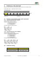
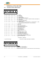
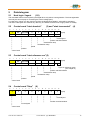
1
SUCOnet K Bus interface for servo drive 635/637’series Product Manual 07-05-02-03-E-V0605.doc Further descriptions, that relate to this document: UL: 07-01-05-06 635 - Product-Manual UL: 07-02-08-03 637 - Product-Manual UL: 07-02-09-01 637+ - Product-Manual UL: 07-02-10-01 637f - Product-Manual UL: 10-06-03 Serial transfer protocol EASY-serial - Product-Manual ©SSD Drives GmbH. All rights reserved. No portion of this description may be produced or processed in any form without the consent of the company. Changes are subject to change without notice. SSD Drives has registered in part trademark protection and legal protection of designs. The handing over of the descriptions may not be construed as the transfer of any rights. Made in Germany, 2005 ________________________________________________________________________________________________________________________________________________________________________________________________________________________ 2 Product Manual Type: SUCOnet K 07-05-02-03-E-V0605.doc CONTENTS page The most important thing first .......................................................................... 4 1 Appendix for user manual 635 and 637’ series for the bus system .... 5 2 Principle function ..................................................................................... 5 2.2 2.3 Bus watching................................................................................................................................... 5 Participant address ......................................................................................................................... 6 3 Short description ...................................................................................... 7 3.1 3.2 Schematic diagram ......................................................................................................................... 7 Bus termination ............................................................................................................................... 8 4 Definitions of the data field ..................................................................... 9 4.1 4.1.1 4.1.2 4.2 4.3 Numbers representation in the serial commands........................................................................... 9 2 byte hexadecimal values (WORD) .............................................................................................. 9 4 byte hexadecimal values (LWORD) ............................................................................................ 9 Parameter scaling........................................................................................................................... 9 Contents of the control word......................................................................................................... 10 5 Data telegram .......................................................................................... 11 5.1 5.2 5.3 5.4 5.5 5.6 5.7 5.8 5.9 5.10 5.11 5.12 5.13 5.14 5.14.1 5.15 5.16 5.17 5.18 5.19 5.20 5.21 Host login / logout(1/2).................................................................................................................. 11 Control word "start absolute"(3) and "start incremental"(4).......................................................... 11 Control word "start reference run"(5)............................................................................................ 11 Control word "Stop"(6) .................................................................................................................. 11 Control word "Stop with breaking ramp"(7) .................................................................................. 12 Control word " preset counter "(8) ................................................................................................ 12 Control word " set BIAS processing pointer "(9)........................................................................... 12 Control word "move +"(10) and "move -"(11) ............................................................................... 13 Control word "move synchronous"(12) ......................................................................................... 13 Control word " synchronous setting "(13) ..................................................................................... 13 Control word " eyemark control 1"(14).......................................................................................... 14 Control word " eyemark control 2"(15).......................................................................................... 14 Control word "virtual axis"(16) ...................................................................................................... 14 Control word "read data block"(17)............................................................................................... 14 Input data ...................................................................................................................................... 15 Control word "write data block"(18) .............................................................................................. 16 Control word reserved(19) ............................................................................................................ 16 Control worde 635/637’ series: "disable/ enable"(20/21)"RESET"(22)"save data "(23) .............. 17 Control word " operating mode speed loop"(24) .......................................................................... 17 Control word "write/read, variable / flags"(25) .............................................................................. 18 Receive buffer (635/637’ series → PLC) ...................................................................................... 20 Data contents of the receive buffers............................................................................................. 21 6 7 8 9 Pin assignment COM 2 bus interface SUCOnet K via RS485............. 22 Example for operating the 635/637’ series via the SUCOnet K field bus system ................................................................. 23 Table of the block numbers................................................................... 25 Standard reference modes overview.................................................... 30 9.1 9.2 9.3 9.4 9.5 9.6 Reference run and modes ............................................................................................................ 30 Reference run to the resolver zero position ................................................................................. 31 Reference run to the reference sensor......................................................................................... 32 Reference run to the reference sensor and the resolver zero position ........................................ 33 Reference run with automatic selection of direction..................................................................... 33 Reference run with shifting of reference point.............................................................................. 34 10 11 Appendix ................................................................................................. 35 Update list ............................................................................................... 36 ________________________________________________________________________________________________________________________________________________________________________________________________________________________ 07-05-02-03-E-V0605.doc Product Manual Type: SUCOnet K 3 The most important thing first Thanks for your confidence choosing our product. These operating instructions present themselves as an overview of the technical data and features. Please read the operating instructions before operating the product. If you have any questions, please contact your nearest SSD Drives representative. Improper application of the product in combination with dangerous voltage can lead to injuries. In addition, damage can also occur to motors or other products. Therefore please observe our safety precautions strictly. Safety precautions We assume that, as an expert, you are familiar with the relevant safety regulations, especially in accordance with VDE 0100, VDE 0113,VDE 0160, EN 50178, the accident prevention regulations of the employers liability insurance company and the DIN regulations and that you are able to use and apply them. As well, relevant European Directives must be observed. Depending on the kind of application, additional regulations e.g. UL, DIN are subject to be observed. If our products are operated in connection with components from other manufacturers, their operating instructions are also subject to be observed strictly. ________________________________________________________________________________________________________________________________________________________________________________________________________________________ 4 Product Manual Type: SUCOnet K 07-05-02-03-E-V0605.doc 1 Appendix for user manual 635 and 637’ series for the bus system SUCOnet K The SUCOnet K Bus interface (Option: RP_SUC) can be integrated in the digital drives 635 or 637’ series as an option board. The option get the supply voltage via the terminal strip. With this option the bus connection with SUCOnet K (Klöckner Moeller) is possible with the 635 or 637’ series as a slave via the physical interface RS 485. 2 Principle function The SUCOnet K system works on the master slave mode. A master can communicate with a maximum of 126 slaves. The transmission rate depends on the bus cable length and is configurable over the programming software SUCOsoft S 30-S 4-200. The configuration is as follows: (without repeater) 187,5 kBit/s: up to 600 m cable length 375 kBit/s: up to 300 m cable length For the bus cable you shoud use a twisted pair cable with shield. Für die Kommunikation muss auf dem Bus ein definierter Ruhepegel gewährleistet werden. Dazu verfügt It is necessary for the bus signals to use bus resistors at the first (master) and at the last (slave). On the SUCOnet K bus interface card mounted on the 635/637 there are jumpers which you have to close for the last slave You can program this identification number in the programming software SUCOsoft S 30-S 4-200 appliance configuration For the 635/637’ series the following appliance type will be used: SIS-TYP-A0EF Note: Knowledge of the PLC PS 4 - series 200 and the programming software (DOK 9026 - x) is requested. In the programming software SUCOsoft S 30-S 4-200 appliance configuration each participant on the bus has to have an appliance type as well as an amount of used data bytes. This information must be transferred to the master. For the 635/637’ series you have to fill in 16 bytes for the receive and transmit data length In this configuration file the participant will automatically get a participant number (1 - 126). This number appears in the upper left hand corner of the configuration screen 2.2 Bus watching The 635/637’ series makes it possible, to detect a bus break and to execute a definition reaction For that, the bus watching must be activated by the master! Follow reaction can activate after detected a bus break: - no reaction - stop abrupt - stop with braking ramp - disable 635/637’ series ________________________________________________________________________________________________________________________________________________________________________________________________________________________ 07-05-02-03-E-V0605.doc Product Manual Type: SUCOnet K 5 Principle function 2.3 Participant address The selection and the setting made by the EASYRIDER ® software in the menu1 → commissioning → fieldbusmodule → mode. The station address will be set 635/637 via DIP-switches (see page 10) on the interface card or via the EASYRIDER software. - valid address range: 1 - 126 If the station address should be set by the EASYRIDER software, the DIL-switches must set smaller than 2 By the EASYRIDER software you have to program the address in the menu 1 → commissioning → fieldbusmodule → participant address. Attention! The participant address must be one more than the participant number. After programming store this with button in the EEPROM. Table: participant address (635/637’series) 00 01 02 03 ... 127 participant number (PLC) reserved Master 1. Slave 2. Slave ... 126. Slave Make sure, that the setting of a bus address is always transferred to the communication program on the interface-board, only during initialization of the 635/637’ series, that is after switching on the supply voltage (24V). i. e.: For taking over the valid participant address, switch the supply voltage on and off again. 1 up to EASYRIDER version 4.05 is valid: settings configuration axis number ________________________________________________________________________________________________________________________________________________________________________________________________________________________ 6 Product Manual Type: SUCOnet K 07-05-02-03-E-V0605.doc 3 3.1 Short description The resistor jumper must be closed on the interface card as last participant on the bus. SUCOsoft configurator (software SUCOsoft S 30-S 4-200) - For the 635/637’ series select the appliance type SIS-Type-A0EF. - The receive and transmit data length is 16 bytes. EASYRIDER program - You must add one to the participant address for the slave and enter it in the 635/637’series via the EASYRIDER software.(For example, participant no. 2 in the PLC configurator is → axis no. in the 635/637’ series) - Store the data with button in theEEPROM Switch the supply voltage 24V of the 635/637’ series on and off again, to take over the valid participant address. Connect the 635/637’ series with the bus cable. Programming software SUCOsoft S 30-S 4-200 - It is possible to make a first function check in the menu "APPLIANCE /IQ STATUS". Schematic diagram ________________________________________________________________________________________________________________________________________________________________________________________________________________________ 07-05-02-03-E-V0605.doc Product Manual Type: SUCOnet K 7 Short description 3.2 Bus termination If an drive from SSD Drives used as the last participant on the SUCOnet K bus system, the terminating resistors must be closed. (switch on jumper 9 and 10) a) 635 top view b) 637’ series - top view ________________________________________________________________________________________________________________________________________________________________________________________________________________________ 8 Product Manual Type: SUCOnet K 07-05-02-03-E-V0605.doc 4 Definitions of the data field Definition of the data field in the SUCOnet K fieldbus system for the 635/637’ series: Output data (master → Digital drive 635/637’ series): 16 byte data unit 0. 1. 2. 2 3. 4. 2 5. 6. 2 7. 8. 2 9. 10. 2 | 11. 2 12. 13. 14. 2 15. 2 (byte) | control word parameter 4.1 Numbers representation in the serial commands 4.1.1 2 byte hexadecimal values (WORD) Number range ±215 (signed integer) Example: The hexadecimal value 0123h represents itself as follows: 01 = High-Byte (Byte 1) 23 = Low-Byte (Byte 2) Precedence within the serial command: 4.1.2 4 byte hexadecimal values (LWORD) Number range ±231 (signed long) Example: The hexadecimal value 01234567h represents itself as follows: 01 = High-Byte (Byte 1) 23 = Low-Byte (Byte 2) 45 = High-Byte (Byte 3) 67 = Low-Byte (Byte 4) Precedence within the serial command: 4.2 Parameter scaling number scaling speed: value = v [min-1] value = a [min-1/s] x 5 acceleration, deceleration: ________________________________________________________________________________________________________________________________________________________________________________________________________________________ 07-05-02-03-E-V0605.doc Product Manual Type: SUCOnet K 9 Definitions of the data field 4.3 Contents of the control word Byte 0 : Befehlsauswahl 7 6 5 4 3 2 1 0 | 0 0 0 0 0 0 0 0 0 0 | 0 0 0 0 0 0 0 0 0 0 | 0 0 0 0 0 0 0 0 0 0 | 0 0 0 0 0 0 0 0 0 0 | 0 0 0 0 0 0 0 0 1 1 | 0 0 0 0 1 1 1 1 0 0 | 0 0 1 1 0 0 1 1 0 0 | 0 1 0 1 0 1 0 1 0 1 0 0 0 0 0 0 0 0 0 0 0 0 0 0 0 0 0 0 0 0 0 0 0 0 0 0 0 0 0 0 0 0 0 0 0 0 0 0 0 0 0 0 0 0 0 0 0 0 0 0 0 0 0 0 1 1 1 1 1 1 1 1 1 1 1 1 1 1 1 1 0 0 0 0 0 0 0 0 1 1 0 0 1 1 1 1 0 0 0 0 1 1 1 1 0 0 1 1 0 0 1 1 0 0 1 1 0 0 1 1 0 0 0 1 0 1 0 1 0 1 0 1 0 1 0 1 0 1 * only after host login (0) (1) (2) (3) (4) (5) (6) (7) (8) (9) status host login host logout start absolute * start incremental dimension * start reference run * (Byte 15: reference mode; see chapter 9) stop abrupt stop (with braking ramp) preset counter * set BIAS processing pointer (byte 2, 3 : block pointer 0...1499 only in operating mode position control with BIAS) * (10) move + * (11) move - * (12) move synchronous * (13) synchronous adjustment * (14) eyemark control 1 * (15) eyemark control 2 * (16) virtual axis 1 * (17) read data block (18) write data block * (**) (19) (..) (20) disable 635/637’ series (21) enable 635/637’ series * (22) 635/637’ series RESET ** (23) save data in 635/637’ Serie ** (24) operating mode speed loop (serial) (25) write variable/ flag | command no. (decimal) ** only after host login and 635/637 is disabled byte 1 : status selection 7 6 5 4 3 2 1 0 | 0 0 0 | 0 0 0 | 0 0 0 | 0 0 0 | 0 0 0 | 0 0 0 | 0 0 1 | Status: 0 (00) Byte 2-5: actual position 1 1 (01) Byte 2-5: actual position 2 0 (02) BIAS variable (variable-no. must be entered in the control word byte 2) ________________________________________________________________________________________________________________________________________________________________________________________________________________________ 10 Product Manual Type: SUCOnet K 07-05-02-03-E-V0605.doc 5 Data telegram 5.1 Host login / logout (1/2) The most data frames are accepted by the Digital drive only after a host registration. The host registration must only be sent uniquely to connecting the control voltage (24V). For Host login / logout only the control word from the Digital drive 635/637’ series will be evaluated. The 2nd to 15th bytes can containe any data.only one interface will be have a login (COM1 or COM2). 5.2 Control word "start absolute" 0. 1. 2. 3. 2 low- 2 | | | | | | | control word 5.3 4. 5. 6. 7. 2 high-word 8. 9. 2 | | | | | | position (3) and "start incremental" 10. 11. 2 | | | | | speed 12. 13. 2 14. (4) 15. 2 2 (byte) | | | | | | | not assigned | | position reached window | deceleration ramp acceleration ramp Control word "start reference run" (5) 0. 1. 2. 3. 2 low- 2 | | | | | | | | control word 5.4 4. 5. 6. 7. 2 high-word 1. 2 2. | | | | | | | position 3. 4. 2 5. 9. 2 6. 7. 2 10. 11. 2 | | | | | | speed Control word "Stop" 0. 8. 12. 13. 2 14. 15. 2 2 (byte) | | | | | | | byte 15: reference mode | | | (see chapter 9) | | position reached window | deceleration ramp acceleration ramp (6) 8. 9. 2 10. 11. 2 12. 13. 2 14. 15. 2 2 (byte) | | | | | | | | | | | control word | | | | | | not analyzed | | | | | | | not analyzed | Position reached window | ________________________________________________________________________________________________________________________________________________________________________________________________________________________ 07-05-02-03-E-V0605.doc Product Manual Type: SUCOnet K 11 Data telegram 5.5 Control word "Stop with breaking ramp" 0. 1. 2. 2 3. 4. 2 6. 7. 2 | | | | | | | | | control word 5.6 5. 8. 9. 2 | | | | | | | not analyzed 10. 11. 2 | | | | | | | 1. 2. 3. 2 low- 2 | | | | | | | | control word 5.7 4. 5. 6. 2 high-word | | | | | | | 7. 8. | | | | | | position 14. 15. 2 2 (byte) | | | | | not analyzed | | | position reached window | deceleration ramp 9. 2 13. 2 Control word " preset counter " 0. 12. (7) (8) 10. 11. 2 12. 13. 2 14. 15. 2 | | | | not analyzed | byte 6: 1 ≡ counter 1 2 ≡ counter 2 2 | (byte) | Control word " set BIAS processing pointer " (9) 0. 1. 2 2. 3. 2 4. 5. 2 6. 7. 8. 9. 2 | | | | | | not analyzed | | | BIAS pointer | control word 10. 11. 2 | 12. 13. 2 | 14. 15. 2 | 2 (byte) | ________________________________________________________________________________________________________________________________________________________________________________________________________________________ 12 Product Manual Type: SUCOnet K 07-05-02-03-E-V0605.doc Data telegram 5.8 Control word "move +" 0. 1. 2. 2 3. 4. 2 6. 2 | | | | | | | | | control word 5.9 5. 7. 8. 2 | | | | | | | not analyzed (10) and "move -" 9. 10. 2 | | | | | speed 11. 12. 2 1. 2. 3. 2 low- 2 | | | | | | | | | | control word 4. 5. 6. 2 high-word 7. 14. 2 | | | | not analyzed | acceleration ramp 8. 2 9. 10. 2 11. 1. 2 2. 3. 2 low- | | | | | | | | | | | | control word (byte) | (12) 12. 2 13. 14. 2 15. 2 (byte) | | | | | | | | | | not analyzed | | | | | Byte 7: 0 = apply immediately | | 1 = apply after form length (master) | | | synchronous program no. (1-16); 0 = no profile | form length (master) 5.10 Control word " synchronous setting " 0. 15. 2 Control word "move synchronous" 0. 13. (11) 4. 5. 2 high-word 6. 7. 2 low- 8. 9. 2 high-word 10. 11. 2 12. (13) 13. 14. 2 15. 2 (byte) | | | | | | | | not analyzed | | | | | Byte 10: input profile | | 0 = no profile | | 1 = ramp down ↓ | | 2 = ramp up ↑ | | | offset (master) | gear factor (master) ________________________________________________________________________________________________________________________________________________________________________________________________________________________ 07-05-02-03-E-V0605.doc Product Manual Type: SUCOnet K 13 Data telegram 5.11 Control word " eyemark control 1" 0. 1. 2. 3. 2 low- 2 | | | | | | control word 4. 5. 6. 2 high-word 7. 8. 9. 2 | | | | | form length 10. (14) 11. 2 12. 13. 2 1. 2. 3. 4. 5. 6. 2 2 low-word high-word 2 | | | | | control word 15. 2 2 (byte) | | | | | byte 15: 0 = off | | 1 = on | eyemark window close eyemark window open 5.12 Control word " eyemark control 2" 0. 14. 7. 8. 9. 2 | | | | sensor position 10. (15) 11. 2 12. 13. 2 14. 15. 2 2 (byte) | | | | | | not analyzed | correction time [ms] max. correction 5.13 Control word "virtual axis" (16) 0. 1. 2. 2 3. 4. 2 5. 6. 2 | | | | control word 7. 8. 9. 2 10. 11. 2 | | | | | | not analyzed 12. 13. 2 | | | 14. 15. 2 | | | 2 | | | 5.14 Control word "read data block" (byte) | byte 15: 0 = off 1 = on (17) With 'read data block' the parameters of the requested data block and the following data block in the input data are returned. Only even data block numbers are accepted. 0. 1. 2 2. 3. 2 4. 5. 2 6. 7. 2 8. 9. 2 10. 11. 12. 13. 2 | | | | | | | | | not analyzed | | data block -no. 100h see chapter 8 | reserve control word 14. 15. 2 | 2 (byte) | ________________________________________________________________________________________________________________________________________________________________________________________________________________________ 14 Product Manual Type: SUCOnet K 07-05-02-03-E-V0605.doc Data telegram 5.14.1 Input data 0. 1. 2. 2 3. 4. 2 5. 6. 7. 2 | | | | | | | | | | | reserve control word 8. 9. 10. 11. 4 12. 13. 14. 15. 4 2 (byte) | | | | | | | not analyzed | | data block + 1 | data block data block-no. 100h.see chapter 8 If an invalid block number is requested, the data contents of the input data of bytes 2 - 15 is FFh Special function 0. 1. 2 2. 3. 4. 2 5. 2 6. 7. 2 8. 9. 10. 2 | | | | | | | | | | | not analyzed | | | block-no. (0-37) | | synchronous program no. (1-16) | data block function: 0 = synchronous data control word 11. 12. 13. 2 14. 15. 2 | 2 (byte) | ________________________________________________________________________________________________________________________________________________________________________________________________________________________ 07-05-02-03-E-V0605.doc Product Manual Type: SUCOnet K 15 Data telegram 5.15 Control word "write data block" (18) Changing parameters on the 635/637’ series is only possible if there has been a login through the master (Host login COM 2). If parameters are to be changed on the 635/637’ series, all 8 bytes of the parameter data must always be entered during "write data block" to the selected block number! The table of block numbers is located in the appendix. In this connection, the marked areas can only be changed in the deactivated state of the drive. 0. 1. 2. 2 3. 4. 2 5. 6. 7. 2 | | | | | | | | | | | reserve control word 8. 9. 10. 11. 4 12. 13. 14. 4 15. 2 (byte) | | | | | | | not analyzed | | data block + 1 | data block data block-no. 100h see chapter 8 Special function 0. 1. 2 2. 3. 2 4. 5. 2 6. 7. 2 8. 9. 10. 2 11. 2 12. 13. 14. 2 15. 2 (byte) | | | | | | | | | data | | | block-no. (0-37) | | synchronous program no. (1-16) | data block function: 0 = synchronous data control word 5.16 Control word reserved (19) ________________________________________________________________________________________________________________________________________________________________________________________________________________________ 16 Product Manual Type: SUCOnet K 07-05-02-03-E-V0605.doc Data telegram 5.17 Control worde 635/637’ series: "disable/ enable" (20/21) "RESET" (22) "save data " (23) 0. 1. 2. 2 3. 4. 5. 2 6. 7. 2 8. 9. 2 10. 11. 2 | | | | not analyzed control word 12. 13. 2 | 14. 2 | 15. 2 | (byte) | 5.18 Control word " operating mode speed loop" (24) With this telegram you can send new speed values to the digital drive. With byte 15 you can switch between rated value via the Profibus DP and analog rated value. Caution: If the the speed loop is switched off via the Profibus DP (byte 15 = 0) an analog value possibly applied to connector X10 pin 18 and 5 can be used. 0. 1. 2. 3. 4. 5. 6. 7. 2 8. 9. 2 10. 12. 13. 2 14. 2 2 | | | | | | | | | | | | | | | | | | | not analyzed | | | current limit [value x 0,1A]; max. drive | | | example: 10d ≡ 1A | | integrator [ | speed [ min-1 ] ∆n sec 2 11. | | | 2 | | | 15. 2 (byte) | byte 15: 0 = off 1 = on ] control word A negative speed is created through the 2 complement. e.g. + 2000 ≡ 0x7D0 - 2000 ≡ 0xF82F U In order to use this function the operating mode speed control must selected in the digital drive. This can be done either with the help of EASYRIDER or with the telegram, "write data block". The operating mode is preselected for the digital drive in block number 0x101. ________________________________________________________________________________________________________________________________________________________________________________________________________________________ 07-05-02-03-E-V0605.doc Product Manual Type: SUCOnet K 17 Data telegram 5.19 Control word "write/read, variable / flags" 0. 1. 2. 3. 4. 5. 6. low-word low byte | high Write | | | | control word | | Byte 2: (25) 7. 8....15. high-word low byte | high | | variable, flag-no. (byte) | value 0: write variable 2 3 4 5 6 7 8 ...... 15 0 | | | value no. variable no. (0...255) | Byte 2: | not analyzed 1: write flag 2 3 4 5 ....... 15 1 | | | | state not analyzed flag no. (0... 255) | Byte 2: 2 : write 3 variables successive 2 3 4 5 6 7 8 9 10 11 12 13 14 15 2 | | | value | no. variable no. (0...253) | Byte 2: | value no.+1 | value no.+2 3 : write 4 flags successive 2 3 4 5 6 7 8 ........ 15 3 | | | | | | state | no. +1 +2 +3 flag no. (0...252) | reserved ________________________________________________________________________________________________________________________________________________________________________________________________________________________ 18 Product Manual Type: SUCOnet K 07-05-02-03-E-V0605.doc Data telegram Control word "write/read, variable / flags" (25) Notice: After a write command (byte 2: 0 - 3) the Input buffer explained in chapter 5.21 will be received read requirement | Byte 2: 4 : read 2 variables successive + actual position 1 2 3 4 ..... 15 4 | | | not analyzed variable no. (0...254) Input buffer | Byte 2: 0 25 4 : read 2 variables successive + actual position 1 1 2 25 4 3 4 5 6 7 8 | | | value | no. variable no. (0...254) 9 10 11 12 | value no.+1 13 14 15 | I actual position 1 requirement | Byte 2: 5 : read 8 flags successive 2 3 4 ....... 15 5 | | | not analyzed flag no. (0...248) Input buffer Byte 2: 0 25 5 : read 8 flags successive 1 2 25 5 3 4 5 6 7 8 9 10 11 | | | | | | | | | | state | no. +1 +2 +3 +4 +5 +6 +7 flag no. (0...248) 12 ....... 15 | reserved ________________________________________________________________________________________________________________________________________________________________________________________________________________________ 07-05-02-03-E-V0605.doc Product Manual Type: SUCOnet K 19 Data telegram 5.20 Receive buffer (635/637’ series → PLC) (except by "read data block", see 5.14) 16 byte- data unit 0. 1. 2 2. 3. 2 low- | | | | | | | status word 4. 5. 2 high-word 6. 7. 2 8. 9. 2 10. 11. 2 12. 13. 14. 2 15. 2 (byte) | | | | | | | | | | | status word 2 | | | | status word 1 | | | error status | | 635/637’ series I/O - status | actual speed position 1; position 2; variable ________________________________________________________________________________________________________________________________________________________________________________________________________________________ 20 Product Manual Type: SUCOnet K 07-05-02-03-E-V0605.doc Data telegram 5.21 Data contents of the receive buffers Byte 0: Byte1: Byte 2-5: Byte 6+7: copy of the control word byte 0 (the last command will be stored if > 0) copy of the control word byte 0 (for one data cycle, then 0) actual position 1 / 2 or BIAS variable (byte2) (see "contents of the control word" byte 1) actual speed in rpm Byte 8: Input status 7 6 5 4 3 2 1 0 X10.4 X10.11 X10.25 X10.2 X10.14 X10.15 X10.24 X10.22 Byte 9: Output status 7 Byte 10: 6 5 4 3 2 1 0 X10.12 X10.13 X10.20 X10.23 X10.8 Error status 1 7 6 5 4 3 2 1 0 I2t-motor Overvoltage Temperature of the output stage too high Motor temperature too high Resolver error internal used active before ready Overcurrent (Software) Byte 11: Error status 2 7 6 5 4 3 2 1 0 WatchdogReset Internal stop Overcurrent (Hardware) not used not used EEPROMcheck total Ballast power exceeded I2t-regulator Byte 12: Status word 1 Byte 1 7 6 5 4 3 2 1 0 Setpoint within setpoint zero window Warning output stage temperature Warning I2tregulator Warning motor temperature Warning I2t-motor Ballast active Undervoltage Output stage passive Byte 13: Status word 1 Byte 2 7 6 Limit switch reached Byte 14: Warning2 5 4 3 2 1 0 Speed regulator without I-gain internal used EEPROMstorage runs Warning ballast power N/I switchover internal used Status word 2 Byte 1 7 6 5 4 3 2 1 0 Position reached internal used internal used COM 2 disabled internal used internal used COM 2 host login COM 2 active Byte 15: Status word 2 Byte 2 7 6 5 4 3 2 1 0 Trailing distance ok (dynamically) internal used referenced COM 1 disabled new format started registration error COM 1 hostlogin COM 1 active 2 total warning, without T1 ________________________________________________________________________________________________________________________________________________________________________________________________________________________ 07-05-02-03-E-V0605.doc Product Manual Type: SUCOnet K 21 6 Pin assignment COM 2 bus interface SUCOnet K via RS485 (The 635/637’ series can communicate via the option module RP-SUC with a PLC PS 4 series 200). The SUCOnet K interface is galvanically isolated, which makes the physical transmission free of interference. Provided module: RP-SUC 635/637’ series - COM 2 Connection plug: SUB D 9-pin PIN no. STATUS Designation Comment 1 n.b not assigned 2 n.b not assigned 3 TA/RA Transmit/Receive 4 n.b not assigned 5 n.b not assigned 6 n.b not assigned 7 TB/RB Transmit/Receive 8 n.b not assigned 9 n.b not assigned ________________________________________________________________________________________________________________________________________________________________________________________________________________________ 22 Product Manual Type: SUCOnet K 07-05-02-03-E-V0605.doc 7 Example for operating the 635/637’ series via the SUCOnet K field bus system 1. Step: Host login via the SUCOnet K bus (once after power on, or always after host logout necessary) ) ) send control telegram with 01h 'Host login' in the control word byte 0 to the 635/637’ series 0. 1. 2. 3. 4. 5. 6. 7. 8. 9. 10. 11. 12. 13. 14. 15. 01 00 xx xx xx xx xx xx xx xx xx xx xx xx xx data byte xx xx : don`t care 2. Step: Check host login ) read response telegram After host login in the response telegram in the data byte 14 the bit 1 'COM2 host login' will be set. 0. ... 14. 00 ... data byte xxxx xx1x |_______________________COM2 'host login'' 3. Step: Position with 'start absolute' ) send control telegram which the control word 'start absolute' and the parameters for position and speed. 1. Example: - position 500.000 increments (500.000d ≡ 0007A120h) - speed 2000 (≡ 7D0h) [1/rpm] - acceleration 1000 (≡ 3E8) [value x 5 - deceleration 1500 (≡ 5DC) [value x 5 - position reached window 100 (≡ 64h) min−1 sec min−1 sec ] ] 0. 1. 2. 3. 4. 5. 6. 7. 8. 9. 10. 11. 12. 13. 14. 15. 03 00 20 A1 07 00 D0 07 E8 03 DC 05 64 00 xx data byte xx | | | | | | | | | | | |__position reached window | | | | |_______deceleration | | | |______________acceleration | | |____________________speed | |______________________________position |_______________________________________start absolute ________________________________________________________________________________________________________________________________________________________________________________________________________________________ 07-05-02-03-E-V0605.doc Product Manual Type: SUCOnet K 23 Example for operating the 635/637’ series via the SUCOnet K field bus system 2. Example: - position 0 increments (00d ≡ 00h) - speed 2000 (≡ 7D0h) [1/rpm] - min−1 sec acceleration 1000 (≡ 3E8) [value x 5 min−1 - deceleration 1500 (≡ 5DC) [value x 5 - position reached window 100 (≡ 64h) sec ] ] 0. 1. 2. 3. 4. 5. 6. 7. 8. 9. 10. 11. 12. 13. 14. 15. 03 00 00 00 00 00 D0 07 E8 03 DC 05 64 00 xx data byte xx | | | | | | | | | | | |__position reached window | | | | |________deceleration | | | |______________acceleration | | |____________________speed | |______________________________position |_______________________________________start absolute 4. Step: check 'position reached' ) read response telegram I When position reached in the response telegram in the data byte 15 the bit 5 'position reached' will be set, or you must compare the position value (byte 2 - 5) with the set value. 0. 2. 3. 4. 5. .... 14. .... 00 00 00 00 00 ... xx1x xxxx ... data byte | | | | | |__________position reached |______________________________________position 0 5. Step: host logout via the SUCOnet K bus ) send control telegram to the 635/637’ series with 02h 'host logout' in the control word byte 0 0. 1. 2. 3. 4. 5. 6. 7. 8. 9. 10. 11. 12. 13. 14. 15. 02 00 xx xx xx xx xx xx xx xx xx xx xx xx xx data byte xx xx : don`t care ________________________________________________________________________________________________________________________________________________________________________________________________________________________ 24 Product Manual Type: SUCOnet K 07-05-02-03-E-V0605.doc 8 Table of the block numbers Note: The marked block numbers may only be changed in the deactivated state of the regulator. Block-no. Meaning 100h Value range Byte X in telegram frame 1 - 255 Byte 4 Axis identification with networking reserved Byte 5 Function identification for ISP function 0-3 Byte6 0 = Output 1 = Input 2 = Stepper motor pulse/direction 3 = Stepper motor pos./negative Output increments 0-3 Byte 7 0 = 1024 1 = 512 2 = 256 3 = 128 101h 635 / 637 operating modes 0-5 0 = torque-speed control 1 = speed control 2 = torque control 3 = position-speed control 4 = position control 5 = position control + BIAS reserved 102h 103h 104h Byte 5 reserved 0/1 Bit 0 in Byte 6 reserved " Bit 1 in Byte 6 1 = 14 BIT Resolver resolution (16384 increments / rpm) " Bit 2 in Byte 6 1 = Motor temperature sensor PTC " Bit 3 in Byte 6 1 = current drop with warning active " Bit 4 in Byte 6 1 = program switch locked " Bit 5 in Byte 6 1 = analog input for external current limiting aktive " Bit 6 in Byte 6 1 = internal ballast present and active " Bit 7 in Byte 6 1 = slope monitoring of the active input " Bit 0 in Byte 7 1 = monitoring control voltage " Bit 1 in Byte 7 1 = position control on actual position 2 " Bit 2 in Byte 7 1 = MP2 for position output " Bit 3 in Byte 7 1 = sinus ramps active " Bit 4 in Byte 7 1 = direction of rotation positive " Bit 5 in Byte 7 reserved " Bit 6 in Byte 7 1 = counter direction actual position 2 positive " Bit 7 in Byte 7 0-4 Byte 4 position reached low time Active OK deceleration table level 0 - 4 in 200 ms steps 0 - 255 ms Byte 5 Byte 6,7 Ucc overvoltage threshold 400 / 765 V UCC- low threshold 15 - 350 V Byte 4,5 UCC-ballast threshold 15 - 400 V Byte 6,7 ballast resistor in 1/10 Ω ballast power 105h Byte 4 10 - 999 ohm Byte 4,5 10 - 999 watt Byte 6,7 reserved Byte 4,5 reserved Byte 6,7 ________________________________________________________________________________________________________________________________________________________________________________________________________________________ 07-05-02-03-E-V0605.doc Product Manual Type: SUCOnet K 25 Table of the block numbers continuation Block-no. Meaning 106h 107h 108h 109h Value range Byte X in telegram frame rated current motor Byte 4,5 number of pole pairs Byte 6,7 EMF/1000min-1 Byte 4,5 Motor inductance (terminal inductance) Byte 6,7 Motor resistance (terminal resistance) Byte 4,5 12T Monitoring time Byte 6,7 resistance value NTC T1 Byte 4,5 resistance value NTC T2 Byte 6,7 10Ah resistance value PTC Byte 4,5 10Bh motor name ASCII 18 bytes Byte 6,7 Byte 4,5 Byte 6,7 10Ch Byte 4,5 Byte 6,7 10Dh Byte 4,5 Byte 6,7 10Eh Byte 4,5 Byte 6,7 10Fh Byte 4,5 reserved 110H 111h 112h Byte 6,7 Maximum current limit - grade value (grade = I_max/32) 0-31 Byte 4,5 P_gain - grade value for the current controller 3 0-31 Byte 6 I_gain - grade value for the current controller 4 P_gain - grade value for the speed controller 4 0-31 Byte 7 0-31 Byte 4 I_gain - grade value for the speed controller 4 0-31 Byte 5 P_gain position controller 1 - 32767 Byte 6,7 I_gain position controller 1 - 32767 Byte 4,5 V_gain position controller 113h 256 - 1/256 Byte 6,7 (0 - 12000) * 1,45 Byte 4,5 0 - 64000 Byte 6,7 0 - 64000 Byte 4,5 Default position reached for position controller in increments 0 - 32767 Byte 6,7 Trailing window in increments 0 - 32767 Byte 4,5 Default speed for position controller in rpm * 1,45 Default braking ramp for position controller [value x 5 114h 115h min−1 sec Default acceleration ramp for position controller [value x 5 Trailing reaction ] min−1 sec ] 0-3 0 = without reaction 1 = stop abrupt 2 = stop 3 = deactivate regulator reserved Byte 6 Byte 7 3 see appendix ________________________________________________________________________________________________________________________________________________________________________________________________________________________ 26 Product Manual Type: SUCOnet K 07-05-02-03-E-V0605.doc Table of the block numbers continuation Block-no. Meaning 116h 10000 = off (without +/- 150 mV Byte 4,5 <= 9999 in 5 min/s Steps Byte 6,7 +/-14000 rpm Byte 4,5 200 - 15000 rpm Byte 4,5 Setpoint evaluation X10 5/18 Setpoint evaluation with torque control 118h Byte X in telegram frame window for 0 V setpoint Setpoint integrator-steepness integrator) 117h Value range in 1/100 A Byte 6,7 Setpoint value norming test point 1 speed Setpoint value norming test point 2 current in 1/100 A 119h Norming analog input external current limiting 1/100 Speed 0 offset storage value +/-311 mV 11Ah Offset resolver position 2 - +10% Imax Byte 6,7 0,1 - 20 V Byte 4,5 +/-512 Byte 6,7 always 0 Byte 4,5 reserved Byte 6,7 11Bh .... reserved 136h 800h - 8FFh Reserved for EASYRIDER extra info 900h - 9FFh Initializing data for the 16 possible synchronous profiles A00h A01h A02h Input definition input X 10.2 (function 0 - 3 see operating instructions) 0-3 Byte 4 Input definition input X 10.4 0-3 Byte 5 Input definition input X 10.11 0-3 Byte 6 Input definition input X 10.14 0-3 Byte 7 Input definition input X 10.15 0-3 Byte 4 Input definition input X 10.24 0-3 Byte 5 Input definition input X10.25 0-3 Byte 6 Byte 7 Output definition output X 10.12 0-2 Output definition output X 10.1 0-2 Byte 4 Output definition output X 10.20 0-2 Byte 5 Output definition output X 10.23 0-2 Byte 6 reserved A03h reserved A04h COMMAND x Byte 7 Byte 4-7 10 position sets a' 14 byte A05h position set 0 0 - 255 (see EASYRIDER) free " - Byte 5 speed in rpm * 1,45 " (0 - 12000) * 1,45 Byte 6,7 " 0 - 32000 Byte 4,5 " 0 - 32000 Byte 6,7 position reached window in increments " 0 - 32767 Byte 4,5 setpoint position low word " 32 Bit Byte 6,7 setpoint position high word " 32 Bit Byte 4,5 position set 1 0 - 255 (see EASYRIDER) Byte 6,7 acceleration ramp [value x 5 braking ramp [value x 5 A06h A07h Ð min−1 sec min−1 sec ] ] COMMAND .... Byte 4 " .... A26h long SOLL_POS; high word position set 9 ________________________________________________________________________________________________________________________________________________________________________________________________________________________ 07-05-02-03-E-V0605.doc Product Manual Type: SUCOnet K 27 Table of the block numbers continuation Block-no. Meaning Value range A027h special funktion I_Conversion 4 Byte float A028h special funktion S_Conversion 4 Byte float A029h pulse_z2 4 Byte Byte X in telegram frame .... A3F reserve A40h - A7Fh BIAS program info data A40h A41h BIAS_START_SET 0 - 1499 BIAS_STOP_MODE 0/1 SPS_STOP_MODE 0-2 VIRTUAL_MODE A42h .... 0 Program name 64 Byte .... A51h A52h BIAS - program data Byte 1 - 4 A54h BIAS - program data Byte 9 - 12 A55h BIAS -program version Byte 1 - 4 A56h BIAS -program version Byte 5 + 6; reserve 2 Byte A57h reserved until A7Fh BIAS - program data Byte 5 - 8 A80h-ABFh BUS module data A80h until A83h reserve A84h SUCOnet_K BUS Axis-number 1 - 255 SUCOnet_K BUS Bus interruption 0-3 0 = without reaction 1 = stop abrupt 2 = stop 3 = deactivate regulator SUCOnet_K BUS braking ramp [value x 5 A85h until A87h reserve A88h PROFIBUS axis-number 0-3 0 = without reaction 1 = stop abrupt 2 = stop 3 = deactivate regulator PROFIBUS braking ramp [value x 5 until A8Bh reserved A8Ch CAN-BUS Node number min−1 sec CAN-BUS Bus interruption CAN-BUS braking ramp [value x 5 0 - 64000 ] 1 - 255 PROFIBUS bus interruption A89h min−1 sec ] ] Byte 5 Byte 6,7 Byte 4 Byte 5 0 - 64000 Byte 6,7 1 - 255 Byte 4 0-3 0 = without reaction 1 = stop abrupt 2 = stop 3 = deactivate regulator min −1 sec Byte 4 0 - 64000 Byte 5 Byte 6,7 ________________________________________________________________________________________________________________________________________________________________________________________________________________________ 28 Product Manual Type: SUCOnet K 07-05-02-03-E-V0605.doc Table of the block numbers continuation Block-no. Meaning A8Dh CAN-BUS baud rate Byte X in telegram frame 0-6 Byte 4 CAN-BUS bus-mode Eurotherm , CAL 0/1 Byte 5 CAN-BUS extended identifier j/n 0/1 Byte 6 CAN-BUS send status automatically j/n 0/1 Byte 7 A8Eh until A8Fh A90h CAN _IID Message 0 A91h CAN _IID Message 1 A92h CAN _IID Message 2 A93h CAN _IID Message 3 A94h CAN _IID Message 4 A95h CAN _IID Message 5 A96h CAN _IID Message 6 A97h CAN _IID Message 7 A98h CAN _IID Message 8 A99h CAN _IID Message 9 A9Ah CAN _IID Message A A9Bh CAN _IID Message B A9Ch CAN _IID Message C A9Dh CAN _IID Message D A9Eh CAN _IID Message E A9Fh CAN _IID Message F AA0h INTERBUS Eurotherm profile = 0, profile 22 = 1 INTERBUS bus interruption INTERBUS braking ramp [value x 5 AA1h Value range 0/1 0-3 0 = without reaction 1 = stop abrupt 2 = stop 3 = deactivate regulator min −1 sec 0 - 64000 ] Byte 4 Byte 5 Byte 6,7 until ABFh AC0h-FFFh res. 1000h 1FFFh Synchronous profiles (according to EASYRIDER calculation) 2000h 2FFFh BIAS program 0 - 1499 blocks (of 8 bytes) see EASYRIDER help set number 0 = adress 2C000H - 2C007h = BUS-command 2000h and 2001h 3000h- 1024 x 64 Byte reseved ________________________________________________________________________________________________________________________________________________________________________________________________________________________ 07-05-02-03-E-V0605.doc Product Manual Type: SUCOnet K 29 9 Standard reference modes overview + 0 1 0 (6) 1 (7) 12 13 18 19 2 3 8 9 14 15 20 21 4 5 10 11 16 17 22 23 + = resolver zero position = reference sensor = positive direction = negative direction = automatic direction selection = reference point shifting 9.1 Reference run and modes The reference run of the axis is always necessary when there must be a fixed relationship between the electrical and the mechanical zero point of the axis, e. g. with a rotary axis with a tool or a linear axis. In order to be able to solve this task flexibly, 24 standard reference modes are offered. These are explained in the following text. ________________________________________________________________________________________________________________________________________________________________________________________________________________________ 30 Product Manual Type: SUCOnet K 07-05-02-03-E-V0605.doc Standard reference modes overview 9.2 Reference run to the resolver zero position The resolver located in the motor represents an absolute position registering system. The zero position of this system can be used to create a zero point with high repeat accuracy. Figure 1 showes a typical application. The axis to be referenced is connected directly with the motor so that a clear coordination between the motor and output position results. Process: The axis executes a counter preset according to the resolver zero position and moves to the zero point in the specified direction. Fig.1: Reference run to the resolver zero position ________________________________________________________________________________________________________________________________________________________________________________________________________________________ 07-05-02-03-E-V0605.doc Product Manual Type: SUCOnet K 31 Standard reference modes overview 9.3 Reference run to the reference sensor Reference runs to an external reference sensor are necessary wherever no exact assignment at the motor to output position can be made. Typical application examples are systems with gearboxes as shown in figure 2 Process: The axis starts the refernce run in the specified direction. The actual position is zeroed upon detection of the low-high slope of the external reference sensor. At the same time the axis is stopped via the active deceleration ramp. Note: 1. If input X10.24 not configured 4 as "reference sensor", a start fault occurs upon execution of a reference run. 2. If the zero position is not reachable in the specified direction5 after stopping the axis, the zero point is not moved to. Fig.2: reference run to an external reference sensor 4 "Configuration", in-, outputs, "function 1-reference sensor" 5 in combination with the automatic selection of direction this limitation does not apply ________________________________________________________________________________________________________________________________________________________________________________________________________________________ 32 Product Manual Type: SUCOnet K 07-05-02-03-E-V0605.doc Standard reference modes overview 9.4 Reference run to the reference sensor and the resolver zero position + The reference modes with reference sensor and resolver zero position represent a combination of the induvidual modes. They are always required wherever no clear coordination of motor position to output position can be made on the one hand. On the other hand, however the high repeat accuracy of the resolver zero point is required. Typical applications are also on the other hand systems with gearboxes 6 (see figure 2) Process: The axis starts the reference run in the specified directions. A counter preset is executed according to the following resolver zero position selection of the high-low slope of the external reference sensor. At the same time the axis is stopped via the active deceleration ramp. If the zero point can be reached in the specified direction, this is subsequently moved to. Note: 1. If input X10.24 is not configured as "reference sensor" a start fault will occur upon execution of a reference run. 2. If the zero position is not reachable in the specified direction after stopping the axis, the zero point will not be moved to. 9.5 Reference run with automatic selection of direction The previous reference types can be combined with the automatic selection of direction. If the automatic selection of direction is active, there are 2 differences. 1. The axis can use both reference directions. As a result, the zero point can always be moved to. 2. With reference modes with reference sensor, the reference run is started in the opposite direction if the reference sensor is already activeat the start of the reference run (see figure 3). After the reference sensor becomes free (inactive) the axis is stopped (see figure 4). Subsequently the reference sensor is moved to in the specified reference direction and the reference run is ended according to the reference mode. Fig. 3: Start of reference run with automatic selection of direction Figure 4: 6 With rotary axes the gearbox ratio must, however, allowa clear position assignment ________________________________________________________________________________________________________________________________________________________________________________________________________________________ 07-05-02-03-E-V0605.doc Product Manual Type: SUCOnet K 33 Standard reference modes overview 9.6 Reference run with shifting of reference point The previous reference modes can also be combined with the reference point shifting. With this, the actual position 0 is shifted by the amount specified in the "path" parameter from the zero point found according to the reference modes (see figure 5). Note: 1. Is the actual position 0 is not reached in the specified direction after stopping the axis , the actual position 0 is not moved to. Figure 5: Reference point shifting ________________________________________________________________________________________________________________________________________________________________________________________________________________________ 34 Product Manual Type: SUCOnet K 07-05-02-03-E-V0605.doc 10 Appendix Assignment of the table positions for P- and I-gain in the current and speed controller to the physical value Index 0 1 2 3 4 5 6 7 8 9 10 11 12 13 14 15 16 17 18 19 20 21 22 23 24 25 26 27 28 29 30 31 current controller P- gain I- gain in 1/ms 0,77 1/80 0,87 1/69,6 0,99 1/60,55 1,12 1/52,68 1,27 1/45,83 1,44 1/39,87 1,64 1/34,69 1,86 1/30,18 2,11 1/26,26 2,4 1/22,85 2,73 1/19,88 3,1 1/17,3 3,52 1/15,05 4 1/13,09 4,55 1/11,39 5,17 1/9,91 5,88 1/8,62 6,68 1/7,5 7,59 1/6,53 8,62 1/5,68 9,8 1/4,94 11,14 1/4,3 12,66 1/3,74 14,39 1/3,25 16,35 1/2,83 18,58 1/2,46 21,11 1/2,14 23,99 1/1,86 27,26 1/1,62 30,98 1/1,41 35,2 1/1,23 40 1/1,07 Index 0 1 2 3 4 5 6 7 8 9 10 11 12 13 14 15 16 17 18 19 20 21 22 23 24 25 26 27 28 29 30 31 speed controller P- gain I-Anteil in 1/ms 0,75 120 0,87 1/103,2 1,01 1/88,75 1,17 1/76,33 1,36 1/65,64 1,58 1/56,45 1,84 1/48,55 2,14 1/41,75 2,49 1/35,91 2,9 1/30,88 3,37 1/26,56 3,92 1/22,84 4,56 1/19,64 5,3 1/16,89 6,16 1/14,53 7,16 1/12,5 8,33 1/10,75 9,69 1/9,25 11,27 1/7,96 13,1 1/6,85 15,23 1/5,89 17,71 1/5,07 20,59 1/4,36 23,94 1/3,75 27,84 1/3,23 32,37 1/2,78 37,64 1/2,39 43,77 1/2,06 50,89 1/1,77 59,17 1/1,52 68,8 1/1,31 80 1/1,13 Assignment of the transmitted parameters to the physical values P - gain physicalic value * 8 I - gain physicalic value * 150 V - gain percentage * 2,56 ________________________________________________________________________________________________________________________________________________________________________________________________________________________ 07-05-02-03-E-V0605.doc Product Manual Type: SUCOnet K 35 11 Update list Version Amendment Chapter Date Name Remarks V04.31HM97 V05.22HM99 none chapter re-worked text addition text addition chapter re-worked separate German / English SSD Drives 4 - 4.3 5.1 5.18 5.19 16.03.1999 K. Stadler ET - Format 31.05.1999 H. Mund V0605 Logo 24.02.2005 N. Dreilich ________________________________________________________________________________________________________________________________________________________________________________________________________________________ 36 Product Manual Type: SUCOnet K 07-05-02-03-E-V0605.doc AUSTRALIA Eurotherm Pty Ltd Unit 1 20-22 Foundry Road Seven Hills New South Wales 2147 Tel: +61 2 9838 0099 Fax: +61 2 9838 9288 CANADA SSD Drives Inc 880 Laurentian Drive Burlington Ontario Canada, L7N 3V6 Tel: +1 905 333-7787 Fax: +1 905 632-0107 CHINA Eurotherm Pty Ltd Apt. 1805, 8 Building Hua Wei Li Chao Yang District, Beijing 100021 Tel: +86 10 87785520 Fax: +86 10 87790272 DENEMARK SSD Drives Enghavevej 11 DK-7100 Vejle Tel: +45 70 201311 Fax: +45 70 201312 FRANCE SSD Drives SAS 15 Avenue de Norvège Villebon sur Yvette 91953 Courtaboeuf Cedex / Paris Tel: +33 1 69 185151 Fax: +33 1 69 185159 GERMANY SSD DRIVES GmbH Von-Humboldt-Straße 10 64646 Heppenheim Tel: +49 6252 7982-00 Fax: +49 6252 7982-05 HONG KONG Eurotherm Ltd Unit D 18/F Gee Chang Hong Centre 65 Wong Chuk Hang Road Aberdeen Tel: +852 2873 3826 Fax: +852 2870 0148 INDIA Eurotherm DEL India Ltd 152, Developed Plots Estate Perungudi Chennai 600 096, India Tel: +91 44 2496 1129 Fax: +91 44 2496 1831 IRELAND SSD Drives 2004/4 Orchard Ave Citywest Business Park Naas Rd, Dublin 24 Tel: +353 1 4691800 Fax: +353 1 4691300 ITALY SSD Drives SpA Via Gran Sasso 9 20030 Lentate Sul Seveso Milano Tel: +39 0362 557308 Fax: +39 0362 557312 JAPAN PTI Japan Ltd 7F, Yurakucho Building 10-1, Yuakucho 1-Chome Chiyoda-ku, Tokyo 100-0006 Tel: +81 3 32132111 Fax: +81 3 32131900 KOREA SSD Korea Co., Ltd. 1308, Daeryung Techno Town 8th Bldg., 481-11 Gasan-Dong, Geumcheon-Gu, Seoul 153-803 Tel: +82 2 2163 6677 Fax: +82 2 2163 8982 NETHERLANDS Eurotherm BV Genielaan 4 2404CH Alphen aan den Rijn Tel: +31 172 411 752 Fax: +31 172 417 260 Poland OBR-USN ul. Batorego 107 PL 87-100 Torun Tel: +48 56 62340-21 Fax: +48 56 62344-25 Romania Servosisteme SRL Sibiu 17 061535 Bukarest Tel: +40 723348999 Fax: +40 214131290 SCHWEDEN SSD Drives AB Montörgatan 7 S-30260 Halmstad Tel: +46 35 177300 Fax: +46 35 108407 SPAN Eurotherm Espana S.A. Pol. Ind. Alcobendas C/ La Granja, 74 28108 Madrid Tel: +34 91 661 60 01 Fax: +34 91 661 90 93 SWITZERLAND Indur Antriebstechnik AG Margarethenstraße 87 CH 4008 Basel Tel: +41 61 27929-00 Fax: +41 61 27929-10 United Kingdom SSD Drives Ltd New Courtwick Lane Littlehampton West Sussex BN17 7RZ Tel: +44 1903 737000 Fax: +44 1903 737100 U.S.A SSD Drives Inc. 9225 Forsyth Park Drive Charlotte North Carolina 28273-3884 Tel: +1 704 588 3246 Fax: +1 704 588 3249 Local availability and service support also in: Argentina · Austria · Bangladesh · Brazil · Chile · Colombia · Costa Rica · Cyprus · Czech Republic · Ecuador · Greece · Hungary · Indonesia Iceland · Israel · Kuwait · Lithuania · Malaysia · Marocco · Mexico · New Zealand · Nigeria · Peru · Philippines · Portugal · Saudi Arabia · Singapore · Slovenia · Sri Lanka · South Africa · Taiwan · Thailand · Turkey · United Arab Emirates · Vietnam SSD Drives GmbH Head Office Plant Servosystems Von-Humboldt-Straße 10, D-64646 Heppenheim Telefon +49 (0)6252 7982-00, Fax +49 (0)6252 7982-05 www.SSDdrives.com · Im Sand 14, D-76669 Bad Schönborn Telefon +49 (0)7253 9404-0, Fax +49 (0)7253 9404-99 [email protected]