1
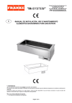
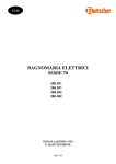
04/2013
Mod: DPA/BSV18
Production code: 8046419
“SELF IN”
I
GB
A010336 Rev. 1
- MANUALE D’INSTALLAZIONE, USO E M ANUTENZIONE
PER ELEM ENTI BAGNOM ARIA VENTILATO AD INCASSO
- INSTALLATION, OPERATING AND M AINTENANCE M ANUAL
FOR VENTILATED BAIN-MARIE UNITS
Pagina 1 di 10
I
MANUALE D’INSTALLAZIONE, USO E MANUTENZIONE
PER ELEMENTI BAGNOMARIA VENTILATO AD INCASSO
“SELF IN”
1. AVVERTENZE
Leggere con attenzione il presente Manuale prima di procedere all’installazione.
Il Manuale è concepito per dare all’utilizzatore le informazioni necessarie all’impiego dell’apparecchiatura in condizioni di sicurezza, dal trasporto al momento
dello smantellamento.
Il manuale deve essere conservato con cura, per essere disponibile in caso di future consultazioni. In caso di cessione dell’apparecchiatura, il manuale deve
essere consegnato al nuovo utente.
·
·
·
·
·
·
Per un corretto utilizzo dell’apparecchiatura:
Non manomettere i dispositivi di sicurezza;
Utilizzare solo per gli scopi specificatamente previsti;
Evitare la presenza di personale estraneo in prossimità dell’apparecchiatura;
Impiegare per la manutenzione esclusivamente personale qualificato;
Disattivare l’apparecchiatura in caso di guasto o di funzionamento irregolare;
Utilizzare esclusivamente ricambi forniti dal Costruttore o da questi indicati.
ATTENZIONE: L’ACCESSO AL QUADRO ELETTRICO PRINCIPALE E A TUTTE LE ALTRE PARTI ELETTRICHE, SIA PER L’INSTALLAZIONE
CHE PER LA MANUTENZIONE, È AUTORIZZATO SOLO A PERSONALE QUALIFICATO.
Il Costruttore declina ogni responsabilità per i danni a cose o persone causati dalla mancata osservanza delle istruzioni e precauzioni contenute nel
manuale.
Per qualsiasi dubbio o necessità rivolgersi al RIVENDIT ORE.
2. INTRODUZIONE
L’apparecchiatura è conforme alle Direttive2004/108 CEE e 2006/95 CEE.
Sono state inoltre applicate le norme CEI EN 60335-1, CEI EN 60335-2-49, CEI EN 60335-2-50, EN 55014, EN 61000-3-2 ed
EN 61000-3-3.
3. DESCRIZ IONE DELLE APPARECCHIATURE
I nostri ELEMENTI BAGNOMARIA sono costituiti da una vasca saldata al piano e raggiata su tutti i lati per consentire una facile pulizia.
La loro funzione è il mantenimento dei cibi caldi nelle bacinelle GN 1/1.
La gamma è composta da modelli di capacità 2,3,4,5,6 GN 1/1, adatta al contenimento di bacinelle con profondità 200mm.
La temperatura massima di funzionamento e di circa 75°C. Pannello di controllo con termoregolatore digitale.
4. TRASPORTO E MOVIMENTAZIONE
Se l’apparecchiatura viene trasportata su pallet deve essere scaricata mediante carrello elevatore o altro macchinario di sollevamento idoneo, manovrati da
personale addestrato. Il peso massimo è indicato in Tabella A.
Eventuali errori di manovra potrebbero causare infortuni per schiacciamento. Qualora le superfici dell’apparecchiatura subissero urti esse sarebbero
immediatamente rovinate.
In questa fase deve essere vietata la sosta nelle immediate vicinanze a chiunque non sia coinvolto direttamente nell’operazione.
Il personale che effettua la movimentazione deve essere munito di mezzi di protezione personale adeguati (ad es.: guanti da lavoro, scarpe
antinfortunistiche).
5. CONDIZIONI DI UTILIZZO E CARATTERISTICHE TECNICHE
I nostri ELEMENTI BAGNOMARIA sono concepiti unicamente per mantenere ed esporre vivande riscaldate, contenute in appositi contenitori unificati, in
locali adibiti alla ristorazione collettiva. Ogni altro impiego è da ritenersi improprio.
La temperatura max di funzionamento della vasca è di 75° C.
Gli ELEMENTI BAGNOMARIA sono disponibili secondo le configurazioni riportate nella Tabella A.
5.1 Comandi e controlli
I dispositivi di comando sono raggruppati sul cruscotto descritto in Fig. 1. I componenti elettrici sono a norma.
·
·
·
5.2 Protezioni e dispositivi di sicurezza
Dispositivi di sicurezza:
Termostato di sicurezza a riarmo manuale presente regolato ad una temperatura di 160° che interviene in caso di funzionamento anomalo. Il termostato si
trova nella parte sottostante la vasca, la posizione del pulsante di riarmo viene segnalata da un adesivo
Dispositivi di protezione individuale:
Si consiglia l’uso di presine o guanti a causa della temperatura raggiungibile dai contenitori delle vivande.
Disposizioni particolari a copertura di rischio residuo:
Limitare l’accesso alle sole persone addette, che devono essere informate sui pericoli potenziali dovuti alla temperatura.
6. INSTALLAZIONE
6.1 Operazioni preliminari
L’utilizzatore deve predisporre l’alimentazione elettrica secondo quanto riportato in Fig. 3, nel rispetto delle norme vigenti.
6.2 Posizionamento
Posizionare l’apparecchiatura con l’eventuale aiuto di un transpallet. Se questo spostamento avviene dopo il disimballo, proteggere le superfici dagli urti.
Una volta completata l’installazione è possibile togliere la pellicola protettiva. L’operazione va fatta molto lentamente per evitare che la colla rimanga sulle
superfici. Qualora ciò avvenga, passare con kerosene o benzina.
I
6.3 Collegamenti elettrici
A010336 Rev. 1
Pagina 2 di 10
Devono essere effettuati da personale qualificato nel rispetto delle norme locali vigenti. Il circuito elettrico dell’apparecchiatura è progettato per funzionare
con una tensione di alimentazione secondo le configurazioni riportate nella Tabella A, con frequenza a 50/60Hz. Vedere schema elettrico Fig. 2 riferito al
modello acquistato.
Il collegamento elettrico avviene collegando un cavo alla morsettiera dell’apparecchiatura.
Il cavo deve avere delle caratteristiche minime del tipo H05 RNF ed un conduttore di terra efficiente e correttamente dimensionato in base alla potenza totale
di questo apparecchio e degli eventuali altri apparecchi o accessori collegati sulla stessa morsettiera (vedi targhetta) L’impianto elettrico di alimentazione
dell’apparecchio deve essere dotato, a monte, di un interruttore automatico onnipolare correttamente dimensionato che garantisca un’apertura fra i contatti di
almeno 3 mm. Il cavo di terra non deve essere interrotto.
La sicurezza elettrica di questa apparecchiatura è assicurata unicamente quando sono soddisfatte le condizioni predette e se il sistema è in regola anche
sotto il profilo dell’equipotenzialità (utilizzare la vite di collegamento posta in prossimità dell’entrata del cavo di alimentazione e dell’adesivo con simbolo)
Il costruttore declina ogni responsabilità in caso di mancato r ispetto di queste norme antinfortunistiche.
7. FUNZIONAMENTO / USO
·
·
·
·
·
·
·
7.1 Consigli per l’uso
Questa apparecchiatura dovrà essere destinata solo all’uso per la quale è stata espressamente concepita: cioè il mantenimento a dei cibi in contenitori GN.
Ogni altro uso è da ritenersi improprio.
Le dimensioni della vasca sono tali da ospitare in lunghezza rispettivamente 2, 3, 4,5,6 moduli GN 1/1.
Prima di utilizzare l’apparecchiatura per la prima volta, pulire l’interno con acqua tiepida e sapone neutro, sciacquare ed asciugare accuratamente, evitare
l’uso di detersivi o polveri abrasive.
7.2 Messa in funzione della VASCA BAGNOMARIA
Inserire l’interruttore di protezione posto a monte dell’apparecchiatura.
Accendere l’interruttore generale delle resistenze vasca A di Fig. 1.
Accendere il termoregolatore digitale della vasca A di Fig. 1, tenendo premuto per almeno 5 sec. il tasto 4 (vedi figura del termoregolatore)
Regolare il termoregolatore digitale B alla temperatura desiderata (il termoregolatore impostato a 75°C).
Il termoregolatore digitale B indica la temperatura all’interno della vasca.
ATTENZIONE:
Se iL termoregolatore B della vasca si spegne da solo, e anche premendo il tasto 4 (vedi figura del termoregolatore) non si riaccende, il
funzionamento NON è regolare ed è scattato il termostato di sicurezza a riarmo manuale. Spegnere l’interruttore generale e chiamare il
servizio assistenza.
7.3 Termoregolatore digitale
Legenda
1 – Display
2 – Pulsante “aumenta valore”
3 – Pulsante “decrementa valore”
4 – Premuto per almeno 5 sec. attiva la funzione stand-by, Pulsante “funzione di uscita”
5 – Pulsante “accede al setpoint”, accede ai menu’, conferma comandi, visualizza allarmi
6 – Led rosso acceso resistenza accesa
8 – Led rosso acceso allarme attivo, lampeggiante per allarme tacitato
USO
Nel corso del normale funzionamento lo strumento visualizza la temperatura rilevata dalla sonda posta a contatto della vasca.
Per visualizzare l’attuale valore del set point: (valore temperatura scelta), premere e rilasciare il tasto set, appare la scritta “set”, premere nuovamente il tasto
set.
Per modificare il valore del setpoint di lavoro premere e rilasciare il tasto set appare la scritta “set”, premere nuovamente il tasto set, appare il valore
impostato, per modificarlo agire entro 15 secondi sui pulsanti ▲(2) o ▼(3) per aumentare o diminuire il valore; dopo la modifica, per memorizzare il nuovo
valore premere il tasto set.
Il setpoint è impostabile entr o i limiti di temperatura massima e minima stabiliti.
SEGNALAZIONI ED ALLARMI
‘E1’ sul visualizzatore indica sonda termostato guasta indicano una delle seguenti anomalie: tipo di sonda non corretta, sonda difettosa, difetto nei
collegamenti; controllare l’integrità della sonda e la correttezza del collegamento strumento-sonda.
“AH1” sul visualizzatore indica allarme di alta temperatura indica che il valore letto è maggiore al valore max impostato dopo il tempo prestabilito; non
causa nessun effetto sulla regolazione, l’allarme rientra quando la temperatura scende al di sotto del valore max.
“AL1” sul visualizzatore indica allarme di bassa temperatura indica che il valore letto è minore al valore min impostato dopo il tempo prestabilito; non
causa nessun effetto sulla regolazione, l’allarme rientra quando la temperatura sale al di sopra del valore min.
La modifica dei PARAMETRI DI CONFIGURAZIONE del termostato, fissati dal costruttore, deve essere eseguita solo da personale qualificato utilizzando le
istruzioni dello strumento.
7.4 Spegnimento
Spegnere l'apparecchiatura spegnendo l'interruttore generale A.
Disinserire l'interruttore a monte dell'apparecchiatura
In caso di spegnimento prolungato:
a)
escludere l'alimentazione elettrica;
b)
pulire accuratamente la vasca;
c)
proteggere le superfici INOX con un velo di olio di vasellina passando energicamente un panno appena imbevuto con l'olio;
d)
arieggiare periodicamente il locale, lasciando aperte le porte dell'armadio, per evitare lo sviluppo di sgradevoli odori.
8. PULIZIA E MANUTENZIONE
8.1 Manutenzione ordinaria
A010336 Rev. 1
Pagina 3 di 10
I
La manutenzione ordinaria e preventiva consiste essenzialmente nella pulizia settimanale delle parti in acciaio inox con acqua tiepida e sapone, seguita da
un risciacquo abbondante ed un’accurata asciugatura. L’operazione di pulizia deve essere eseguita solo dopo aver staccato l’alimentazione elettrica a monte
dell’apparecchiatura.
In caso di formazione di depositi calcarei sul fondo della vasca, pulire con soluzione di aceto o appositi prodotti, risciacquando poi abbondantemente con
acqua ed asciugare.
·
·
·
·
·
Attenzione:
Evitare assolutamente l’uso di prodotti detergenti abrasivi o corrosivi e di attrezzi come pagliette, spazzole o raschietti metallici.
Varechina, acido cloridrico ed altri composti contenenti cloro danneggiano l’acciaio inox.
Le parti colorate devono essere pulite con cera ai siliconi.
Il pavimento sotto l’apparecchio non deve essere lavato con sostanze corrosive che potrebbero sviluppare vapori che danneggiano l’apparecchiatura.
Durante la pulizia non lavare con getti d’acqua l’apparecchiatura.
8.2 Manutenzione straordinaria
La manutenzione straordinaria avviene in caso di guasto od anomalia da parte di personale qualificato, possibilmente con l’apparecchiatura
disconnessa dalla rete di alimentazione.
In questo ambito possono essere necessarie riparazioni o sostituzioni. Le parti difettose devono essere sostituite solo con materiali e componenti identici a
quelli originali o indicati dal Fornitore.
In caso di sostituzione di componenti o modifica sull’apparecchiatura eseguita dall’utilizzatore senza il consenso scritto del Costruttore, o con ricambi non
autorizzati, la garanzia decade immediatamente.
8.3 Possibili anomalie
Se la VASCA non si riscalda controllare l’alimentazione elettrica e che il termoregolatore digitale non sia regolato al minimo.
Se l'interruttore generale A è in posizione 1 ed è acceso, mentre lo strumento è spento, il funzionamento NON è regolare ed è scattato il termostato di
sicurezza a riarmo manuale. Spegnere l'interruttore generale e chiamare il servizio assistenza.
Se dopo aver effettuato i controlli indicati non si ottiene un funzionamento corretto, spegnere l’apparecchiatura e contattare immediatamente il fornitore.
9. SMANTELLAMENTO
Alla fine della sua vita utile, l’apparecchiatura dovrà essere esclusa dalla rete elettrica prima di procedere allo smontaggio dei vari componenti. Si dovrà fare
attenzione alle possibilità di infortunio connesse con la forma ed il peso di ciascun componente.
Le varie parti (componenti elettrici, tubi in gomma, guaine passacavi, ecc.) andranno selezionate per ottenere il miglior risultato possibile in termini di rispetto
per l’ambiente nel rispetto delle leggi vigenti.
GB
INSTALLATION, OPERATING AND MAINTENANCE MANUAL
FOR VENTILATED BAIN-MARIE UNITS
A010336 Rev. 1
Pagina 4 di 10
“SELF IN”
1. WARNINGS
Read this manual carefully before commencing installation.
The manual has been devised to furnish the user with all the information required to operate the equipment safely, from its transportation right through to
scrapping.
The manual must be looked after carefully so that it is available for future reference. In the event the equipment is sold, the manual must also be handed
over to the new user.
·
·
·
·
·
·
In order to use the equipment cor rectly:
Do not tamper with the safety devices;
Use the equipment only for the purpose for which it was specifically designed;
Keep unauthorized personnel away from the equipment;
Have maintenance performed by qualified personnel only;
Switch off the equipment in the event of a fault or irregular operation;
Only use spare parts supplied or indicated by the Manufacturer.
ATTENTION: ONLY QUALIFIED ELECTRICIANS ARE AUTHORIZED TO ACCESS THE MAIN CONTROL BOARD AND ANY OTHER ELECT RICAL
PARTS, WHETHER FOR INSTALLATION OR MAINTENANCE PURPOSES.
The Manufacturer declines all responsibility for damage to property or bodily injury as a result of non-compliance with the instructions and warnings
contained herein.
If in any doubt, and whenever the need arises, contact the DEALER.
2. INTRODUCTION
The equipment conforms to the EEC Directives 2004/108 CEE e 2006/95 CEE.
In addition, the following standards have also been applied: CEI EN 60335-1, CEI EN 60335-2-49, CEI EN 60335-2-50, EN 55014, EN 61000-3-2 and EN
61000-3-3.
3. DESCRIPTION OF THE EQUIPMENT
Our BAIN-MARIE UNIT S are composed of a basin welded to the top and curved on all sides to allow easy cleaning.
Their purpose is to keep food warm in GN 1/1 basins.
The range is composed of three models with a capacity of 2, 3, 4,5, 6, GN 1/1, suitable for holding basins with a depth of 200mm.
The maximum operating temperature is around 75°C. Control panel with digital heat regulator.
4. TRANSPORTATION AND HANDLING
If the equipment is transported on a pallet, it must be unloaded using a lift truck or other appropriate lifting means operated by trained personnel. The
maximum weight is given in Table A.
Manoeuvring errors might cause injury as a result of crushing. Any blows to the surfaces of the equipment will result in immediate damage.
During this phase, anyone not directly involved in the operation must not be allowed to remain in the area.
The personnel handling the equipment must wear appropriate personal safety gear (e.g. work gloves, safety boots).
5. OPERATING CONDITIONS AND TECHNICAL FEATURES
Our BAIN-MARIE UNITS have been designed solely for the preservation and display of warm foods, contained in special unified containers, for use in
rooms used for group catering. Any other use shall be considered improper.
The maximum operating temperature of the basin is 75° C.
The BAIN-MARIE UNIT S are available in the configurations featured in Table A.
5.1 Controls
The control devices are grouped together on the instrument panel illustrated in Fig. 1. Electrical components conform to standards.
·
·
·
5.2 Protection and safety devices
Safety devices:
Manual-reset safety thermostat in the basin and in the heated cabinet only, set to a temperature of 150°, it trips when operation is anomalous.
Personal safety gear:
The food containers can become very hot, and it is therefore advisable to use pot-holders or oven gloves.
Special provisions guarding against residual hazards:
Make sure authorized personnel only are allowed access to the unit, and that they are suitably instructed as to the potential dangers owing to high
temperatures.
6. INSTALLATION
6.1 Preliminary operations
The user must provide for the supply of electrical energy as shown in Fig. 3, in compliance with current standards.
6.2 Positioning
Move the equipment into place with the aid of a pallet truck, where necessary. If the unit is moved after it has been unpacked, protect the surfaces from
knocks.
Once installation is complete, the protective film can be removed. This operation should be performed very slowly to prevent the glue from remaining
attached to the surfaces. If this happens, use kerosene or petrol to remove it.
GB
6.3 Electrical connections
Connections must be made by a qualified electrician in accordance with the local standards in force. The electrical circuit of the unit is designed to operate
at a power supply voltage in accordance with the configurations shown in Table A, with a frequency of 50/60Hz. See the electrical diagram, Fig. 2, applicable
to the model you have purchased.
The electrical connection is made by connecting the cable to the terminal board of the unit.
The cable must have the features of type H05 RNF or better, and must feature an efficient earth wire of an appropriate size for the total power of this unit
and any other units or accessories connected on the same terminal board (see rating plate). The units electrical supply system must feature an
A010336 Rev. 1
Pagina 5 di 10
appropriately sized automatic omnipolar circuit breaker upstream that assures a gap between the contacts of at least 3mm. There must not be any breaks in
the earth cable.
The electrical safety of this equipment is only assured when the above-mentioned conditions are met and if the systems equipotential situation is also in
order (use the connection screw located near the power cable entry and the
label featuring the symbol)
The manufacturer declines all responsibility in the event these safety standards are not complied with.
7. OPERATION / USE
·
·
7.1 Operating tips
This appliance must only be used for its intended purpose. This consists of keeping foods warm by bain-marie in GN containers. Any other use shall be
considered improper.
The size of the basin means that, lengthwise, it can accommodate 2, 3, 4, 5, 6 GN 1/1 modules respectively.
Before using the equipment for the first time, clean it inside with lukewarm water and neutral soap, rinse and dry thoroughly. Avoid using abrasive detergents
or scouring powders.
7.2 Starting up the BAIN-MARIE BASIN
Turn on the circuit breaker located upstream from the equipment.
Make sure the overflow is properly inserted in the waste.
Turn on the main switch for the basin heating elements A of Fig. 1.
Switch on the basin digital thermostat B of Fig. 1 and press the buttom 4 for at least 5 “ (see picture of thermostat)
Adjust the digital heat regulator B to the desired temperature (the heat adjuster set to 75°C).
The digital heat regulator B indicates the temperature in the basin.
·
·
·
·
·
·
WARNING:
If the digital thermostat B turns off and even pressing the button 4 (see picture of digital thermostat) it doesn’t run, the working IS NOT
CORRECT , the manual-reset safety thermostat goes off. Switch off the general switch and call the assistance service.
7.3 Digital heat regulator
Legend
1- Display
2- “Increase value” button
3- “Decrease value” button
4- Press at least “ to activate the stand-by function , “Exit function” button
5- “Enter setpoint” button, enter controls confirmation menu and alarms view menu
6- Red led alight, heating element on wor king
8- Red led alight, active alarm; if lightening, silenced alarm
USE
During the usual working the instrument shows the temperature pointed out by the feeler which is in contact with the basin or inside the cabinet.
To visualize the present setpoint value: (value of established temperature) push and release set button, the word “set” appears, push again “set” button.
To modify the setpoint value push and release set button, the word “set” appears, push again “set” button and the set value appears. To modify it push by
15 seconds the ▲(2) o▼(3) buttons to increase or decrease the value. After the change push set button to save the new value.
The setpoint can be set by settled limits of the highest and lowest temper ature.
SIGNALS AND ALARMS
“E1” on the display indicates damaged thermostat feeler and there could be one of the following anomaly: basin feeler type not correct, basin feeler
defective, connection defect. Check if the feeler is intact and if connection between instrument and feeler is correct.
“AH1” high temperature alarm on display indicates that the reading value is higher then the pre-setted max. value; it causes no effect to the regulation,
the alarm stops when the temperature decreases under the presetted max. value.
“AL1” low temperature alarm on display indicates that the reading value is lower then the presetted minimum value, it causes no effect to the regulation,
the alarm stops when the temperature rises over the presetted minimum value
Only qualified personnel can modify the CONFIGURATION PARAMETERS of the thermostat, established by the Manufacturer, using
7.4 Shutdown
Turn the unit off via the main switch A.
Switch the equipment off by switching the digital thermostat B off.
THE BASIN MUST ONLY BE DRAINED O NCE THE EQUIPMENT HAS COOLED.
In the event the unit is to be left off for a lengthy period:
a) disconnect the power and water supply;
b) empty the basin and clean thoroughly;
c) protect the stainless steel surfaces by covering them with Vaseline oil, rubbing vigorously with a cloth soaked in the oil;
GB
8. CLEANING AND MAINTENANCE
8.1 Routine maintenance
The routine and preventive maintenance basically consists in the weekly cleaning of the stainless steel parts with lukewarm soapy water, rinsing abundantly
and drying thoroughly. The unit must only be cleaned after first disconnecting the power supply upstream from the equipment.
Should lime scale form on the bottom of the basin, clean with a vinegar solution or special products before rinsing abundantly with water and drying.
·
Attention:
Under no circumstances should you use abrasive or corrosive detergents and utensils such as steel wool, brushes or metal scrapers.
A010336 Rev. 1
Pagina 6 di 10
·
·
·
·
Bleach, hydrochloric acid and other compounds containing chlorine will damage the stainless steel.
The coloured parts must be cleaned with silicone wax.
The floor under the unit must not be washed with corrosive substances that might generate vapours damaging the equipment.
During cleaning, do not wash the equipment with jets of water .
8.2 Non-routine maintenance
Special maintenance must be performed by qualified personnel in the event of a fault or anomaly, wherever possible with the equipment disconnected
from the power mains.
In this case, repairs or replacements might be required. The faulty parts must only be replaced with materials and components identical to the originals or
specified by the Manufacturer.
The replacement of components or the modification of the equipment by the user without written permission from the Manufacturer, or the use of nonauthorized spare parts, shall instantly cause the warranty to be void.
8.3 Possible errors
If the BASIN does not heat, check the power supply and make sure the digital temperature regulator is not at the minimum setting.
If, after performing the checks indicated, correct operation is still not achieved, switch off the equipment and contact the supplier without delay.
9. SCRAPPING
At the end of its service life, the equipment must be disconnected from the power mains before disassembling the various components. Special care must
be taken to avoid the risk of accidents associated with the form and weight of each component.
The various parts (electrical components, rubber piping, cable sheaths, etc.) must be selected so as to make the best possible contribution to the protection
of the environment in compliance with the laws in force.
Tabella A:
CARATTERISTICHE TECNICHE ELEMENTI BAGNOMARIA TECHNICAL FEATURES OF BAIN-MARIE UNITS - TECHNISCHE MERKMALE BAINMARIE-ELEMENTE CARACTERISTIQUES TECHNIQUES ELEMENTS BAIN MARIE
Mod.
IBM2
Dimensioni esterne - Overall dimensions - Aussenmasse mm Dimensions externes mm.:
A010336 Rev. 1
Pagina 7 di 10
IBM3
IBM4
IBM5
IBM6
L=lunghezza- length-Länge- longueur :
P=profondità-depth- Tiefe- profondeur:
H = altezza- height- Höhe- hauteur:
Dimensioni vasca/basin/wanne/bac : mm.:
Lunghezza- length- Länge– longueur : mm
Profondità – depth - Tiefe- profondeur : mm
Altezza – height – Höhe – hauteur : mm
Capacità vasche-Basin capacity-Kapazität- Capacité des
bacs
Potenza totale-Total power-Gesamtleistung KW - Puissance
totale
Tensione alimentazione- Supply voltage- SpeisespannungTension alimentation
Peso Max-Max weight-Höchstgewicht-Poids (Kg).
800
700
280
1125
700
280
1455
700
280
1780
700
280
2105
700
280
660
510
210
990
510
210
1310
510
210
1605
510
210
1930
510
210
2 1/1
3 1/1
4 1/1
5 1/1
6 1/1
1.1
1.1
2.2
3.2
3.3
230V 1N
50/60Hz
30
230V 1N
50/60Hz
40
230V 1N
50/60Hz
50
230V 1N
50/60Hz
60
230V 1N
50/60Hz
70
Fig. 1: PANNELLO COMANDI – CONTROL PANEL – SCHALTFELD - PANNEAU DE COMMANDES
A = INTERRUTTORE GENERALE VASCA
B = TERMOREGOLATORE DIGITALE VASCA
C = INTERRUTTORE LUCI
A = MASTER SWITCH
B = BASIN/SHELF TEMPERATURE THERMOSTAT
C= NEON SWITCH
A = HAUPTSCHALTER
B = THERMOSTAT BEHÄLTER/ABLAGE
C = SCHALTER NEONBELEUCHTUNG
A = INTERRUPTEUR GÉNÉRAL DU BAC
B = THERMORÉGULATEUR NUMÉRIQUE DU BAC
C = INTERRUPTEUR NEON
Fig. 2: SCHEMA ELETTRICO – WIRING DIAGRAM – SCHALTPLAN - SCHEMA ELECTRIQUE
BAGNOMARIAVENTILATO SU VASCA 2/3 GN1/1 - BAIN-MARIE ON BASIN 2/3 GN1/1
BAINMARIE IN DER WANNE 2/3 GN1/1 - BAIN-MARIE SUR BAC 2/3 GN1/1
A010336 Rev. 1
Pagina 8 di 10
BAGNOMARIAVENTILATO SU VASCA 4/5/6 GN1/1 - BAIN-MARIE ON BASIN 4/5/6 GN1/1
BAINMARIE IN DER WANNE 4/5/6 GN1/1 - BAIN-MARIE SUR BAC 4/5/6 GN1/1
Mal
Igv
MORSETTIERA
D’ALLACCIAMENTO
INTERRUTTORE GENERALE
VASCA
MAIN TERMINAL BOARD
ANSCHLUSSKLEM MENLEISTE
BASIN MASTER SWITCH
HAUPTSCHALTER WANNE
In
INTERRUTTORE LUMINOSO LUCI LIGHTING LUMINOUS SWITCH
Tv
TERMOSTATO REGOLAZIONE
VASCA
B
BOBINA TELERUTTORE
BC
CONTATTI TELERUTTORE
R
Ts
X1
RESISTENZA RISCALDANTE
TERMOSTATO DI SICUREZ ZA
MORSETTIERA INTERNA
BASIN REGULATOR
THERMOSTAT
ELECTROMAGNETIC SWITCH
COIL
ELECTROMAGNETIC SWITCH
CONTACTS
BORNIER DE BRANCHEMENT
INTERRUPTEUR GENERAL
BAC
LEUCHTSCHALTER
INTERRUPTEUR LUMINEUX
BELEUCHTUNG
LUMIERES
THERMOSTAT EINSTELLUNG THERMOSTAT REGLAGE
WANNE
BAC
SPULE FERNSCHALTER
BOBINE TELERUPTEUR
KONTAKTE FERNSCHALTER
CONTACTS TELERUPTEUR
HEATING ELEMENT
HEIZKÖRPER
RESISTANCE CHAUFFANTE
SAFETY THERMOSTAT
INTERNAL TERMINAL BOARD
SICHERHEITSTHERMOSTAT
INTERNE KLEM MENLEISTE
THERMOSTAT DE SECURITE
BORNIER INTERNE
Fig. 3: SCHEMA DI INSTALLAZIONE- INSTALLATION DIAGRAM - INSTALLATIONSSCHEMA - SCHEMA
D’INSTALLATION
ELEMENTI BAGNOMARIA - BAIN-MARIE UNITS - BAINMARIE-ELEMENTE - ELEMENTS BAIN-MARIE
A010336 Rev. 1
Pagina 9 di 10
Il Self IN è un prodotto progettato per disporre delle funzioni desiderate integrandole con qualsiasi arredamento previsto dal cliente.
La gamma si compone di elementi caldi e freddi, tutti adatti ad essere incassati su qualsiasi piano.
Gli elementi sono in acciaio inox e le vetrine sono in vetro temprato.
Gli elementi refrigerati sono previsti in versione completa di gruppo refrigerante oppure predisposti per gruppo refrigerante remoto; i primi sono
pronti per l’utilizzo, gli altri necessitano del collegamento al gruppo remoto, della carica di fluido refrigerante e del collaudo.
Predisposizione del foro nei piani di lavoro:
Gastro Norm
Lf [mm]
Pf [mm]
Lp[mm]
Pp [mm]
Hp [mm]
A010336 Rev. 1
2 GN1/1
775
685
800
700
10
3 GN1/1
1100
685
1125
700
10
Pagina 10 di 10
4 GN1/1
1430
685
1455
700
10
5 GN1/1
1755
685
1780
700
10