1
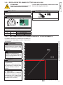
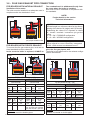
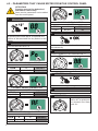
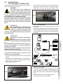
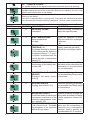
3.12 - ADJUSTING THE BURNER
Attention, during these operations do
not take any samples in domestic hot
water mode.
All boilers leave the factory already calibrated and tested, however in the event
the gas valve recalibration is required:
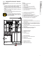
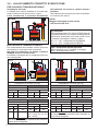
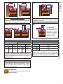
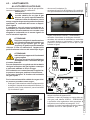
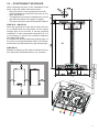
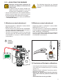
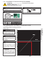
- Loosen the needle screw ‘’P’’ located inside the
pressure socket at gas valve outlet and connect
a pressure gauge with reference to the figure.
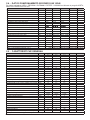
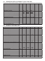
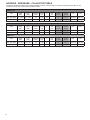
- Check the supply pressure value (see NOZZLES
- PRESSURES table).
The following instructions are intended
exclusively for authorised service personnel.
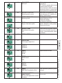
1) Maximum output adjustment
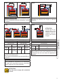
2) Minimum output adjustment
- Operate the boiler in “calibration” mode at MAXIMUM OUTPUT (see 3.11.1).
- Once the burner is on check that the “MAXIMUM”
pressure value corresponds to that indicated in
the table “NOZZLES - PRESSURE”.
- Should it not correspond, correct it by removing
the screw cap ‘’Q’’ and turning screw “S” below
CLOCKWISE to increase it, ANTICLOCKWISE
to decrease it.
- Operate the boiler in “calibration” mode at MINIMUM OUTPUT (see 3.11.1)
- Once the burner is on, check that the “MINIMUM”
pressure value corresponds to that indicated in the
table “NOZZLES - PRESSURE”.
- Correct it if needed by turning (with a screwdriver)
the screw “R”; CLOCKWISE to increase it, ANTICLOCKWISE to decrease it.
Socket
pressure
OUTPUT
INSTALLATION INSTRUCTIONS
ENGLISH
P
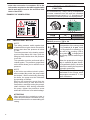
3) Conclusion of the basic calibrations
- once the gas valve minimum and maximum pressure values are checked and top-up is required
(points 1-2):
- disable the timed “calibration” function by switching off the main switch.
- Remove the flexible tube from the pressure
gauge and close the pressure socket screw
again.
- Check that there are no gas leaks.
25