1
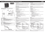
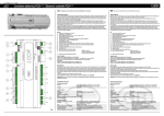
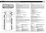
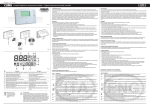
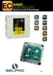
+050000680 - rel. 1.1 del 23.05.2006
FCP -
Regolatore di velocità con controllo a taglio di fase/Speed regulator with phase cutting control
Vi ringraziamo per la scelta fatta, sicuri che sarete soddisfatti del vostro acquisto.
We thank you for your choice and are certain you will be satisfied with your purchase.
Avvertenze generali
Prima di utilizzare il controllo leggere attentamente il manuale d’installazione d’uso del regolatore FCP, nella sezione
“Installazione e manutenzione”, dove sono riportate le note per la corretta installazione, manutenzione ed utilizzo,
oltre a particolari indicazioni per la sicurezza dell’operatore e dell’impianto. Il manuale riporta tutte le informazioni sul
funzionamento del regolatore nelle diverse modalità, su come attivare il collegamento seriale via PC, e come utilizzare la
chiave di programmazione.
Caratteristiche generali
Il regolatore FCP è un regolare di velocità per ventilatori stand-alone con uscita taglio di fase con controllo a microprocessore. Regola la velocità dei ventilatori monofase per le unità di condensazione (condizionamento e refrigerazione) fino a due circuiti, in base alla pressione (o temperatura) del circuito, prendendo come riferimento la
più alta delle due, regolando la velocità per mantenere il valore di set point impostato. Viene fornito con i parametri
impostati per la gestione bicircuito. Il segnale di feedback arriva dai sensori di pressione (raziometrico 0...5 V) o dalle
sonde di temperatura (NTC, tipo STD o HT). Per utilizzare il secondo circuito (ingresso B2) si deve togliere la resistenza
posizionata sulla morsettiera.
Collegamenti elettrici/Electric connections
Fig. 1
Collegamento IngrIngressi/Uscite
LN
L1 N
ID1 GND
Alimentazione controllo 230 Vac
Alimentazione carico 230 Vac. Max L= 2 m
Ingresso digitale configurabile. Protezione motore o gestione secondo set point, vedi configurazione dip
switch; Max L= 2 m
B1 GND +5 V
Ingresso analogico circuito 1 per la lettura pressione (raziometrica) o temperatura (sonda NTC di tipo
veloce modello WF). Max L= 2 m
B2 GND +5 V
Ingresso analogico circuito 2 per la lettura pressione (raziometrica) o temperatura (sonda NTC di tipo
veloce modello WF). Max L= 2 m
B3 GND +5 V
Ingresso NTC per la lettura della temperatura ambiente per algoritmo di Feed-forward. Max L= 2 m
Connettore chiave UPLOAD o DOWNLOAD parametri.
GND
Seriale RS485 con protocollo MODbus slave.
Max L= 1Km per la linea principale. I singoli nodi 50 m dalla linea principale.
RX+/TX+
RX-/TX-
Tab. 6
Attenzione: Dimensionare la sezione dei conduttori di potenza, in base alla corrente del carico.
Inputs/Outputs connection
LN
L1 N
ID1 GND
B1 GND +5 V
B2 GND +5 V
B3 GND +5 V
Key connector
GND
RX+/TX+
RX-/TX-
230 Vac power supply to the control
Load power supply 230 Vac. Max L= 2 m
Configurable digital input. Motor protection or management according to set point - see dip switch
configuration; Max L= 2 m
Circuit 1 analog input for reading pressure (ratiometric) or temperature (fast type NTC probe model
WF). Max L= 2 m
Circuit 2 analog input for reading pressure (ratiometric) or temperature (fast type NTC probe model
WF). Max L= 2 m
NTC Input for reading ambient temperature for the Feed-forward algorithm. Max L= 2 m
UPLOAD or DOWNLOAD parameters
RS485 Serial network with MODbus slave protocol.
Max L= 1Km for the main line. Individual nodes at 50 m from the main line.
Tab. 6
Important: Size the diameter of the power conductors, according to load current.
General warnings
Before using the control, carefully read the installation and use manual of the FCP regulator: in particular, the
“Installation and maintenance” section, which contains notes on correct installation, maintenance and use, in addition
to special instructions about the safety of the operator and system. The manual contains full information on the
operation of the regulator in its different modes, on how to activate the serial connection via the PC, and on how to
use the programming key.
General characteristics
The FCP regulator is a speed regulator for stand-alone ventilators, with a microprocessor controlled phase cutting
output.
It regulates the speed of the single-phase ventilators for the condensation units (conditioning and refrigeration) up to
two circuits, according to the pressure (or temperature) of the circuit, using the higher of the two units as a reference,
and regulating speed to maintain the assigned set point value. It is supplied with parameters set for managing the
bi-circuit. The feedback signal arrives from the pressure sensors (0…5 V ratiometric) or from the temperature probes
(NTC, type STD or HT). To use the second circuit (input B2), the resistor on the terminal-board must be removed.
Il regolatore permette di:
• Ottimizzare la gestione della pressione entro il range impostato, migliorando il rendimento dell’impianto frigorifero nelle diverse condizioni atmosferiche, riducendo i consumi energetici;
• Limitazione della velocità massima per ridurre il rumore del ventilatore, (utile nelle are urbane dove il rumore deve essere controllato sotto una determinata soglia).
What you can obtain with the regulator:
• Optimise pressure management within the set range, improving the performance of the refrigeration system in different atmospheric conditions, and reducing energy consumption;
• Limit maximum speed to reduce ventilator noise (useful in urban areas where noise must be controlled under a specific threshold).
Presenta i seguenti vantaggi:
• Chiave di programmazione;
• Memorizzazione dello stato degli eventi (visibile via PC);
• Ingresso digitale, programmabile (protezione motore/secondo set point);
• Possibilità di configurarlo in modalità minima velocità o Cut-OFF;
• Funzione di Speed-up;
• Sonda ambiente (Feed-forward);
• Doppio set point;
Advantages:
• Programming key
• Memory storage of events status (visible via the PC);
• Programmable digital input (motor protection/second set point);
• Can be configured in minimum speed or Cut-OFF mode
• Speed-up function;
• Ambient probe (Feed-forward);
• Double set point;
Caratteristiche tecniche
Technical specifications
Alimentazione monofase
Frequenza
Potenza assorbita dal circuito di comando
Massima corrente
Minima corrente
Massima tensione d’uscita
Caduta di tensione sul regolatore
Temperatura di lavoro
Umidità ambiente
Temperatura di immagazzinamento
Protezione contro le scosse elettriche
Grado di protezione
Grado di inquinamento del regolatore
Ingressi analogici (vedi nota in seguito)
Gestione Cut-OFF
Caratteristica di invecchiamento
Periodo delle sollecitazioni elettriche delle parti isolanti
EMC
CE
Rhos
Set point
Differenziale
Regolazione minima velocità
Dimensioni
Peso
PTI dei materiali per isolamento
Categoria di resistenza al calore e al fuoco
Immunità contro le sovratensioni
Materiale
230 V +10%/ -15%
50/60 Hz con autosensing
1.5 VA
8 A @ (-20T50°C)
≥ 500 mA
0% to 100% (of supply voltage)
1,5 Vac
-20T50°C
<85% R.H. (non condensante)
-20T70°C
Classe I
IP54
Normale
Tipo raziometrici 0...5 Vdc, 8 mA o NTC
Si o min. velocità vedi Fig. 3
60.000 ore
Lungo
Conforme direttive 72/23 CEE e 89/336 CEE
In base alla norme EN55014-1, EN55014-2, EN60730-1
Conforme alla normativa (tecnologia lead-free)
Regolabile da parametro o trimmer 0...100%
Regolabile da: a) trimmer 0...20%; b) parametro 0...100%
Regolabile da parametro o trimmer 0...100%
140x135x90 mm
1,1 Kg
250 V
Categoria D (UL94 - V0)
Categoria 1
Coperchio in plastica autoestinguente colore RAL7035.
Corpo contenitore in alluminio.
Tab. 1
Nota:
Il regolatore prevede di utilizzare i sensori CAREL:
Press. raziometrici 0...5 V della serie SPKT* con segnale 0,5...4,5 V; oppure
Sensori di temperatura NTC:
-50T90°C per la versione 10K@25 °C con risoluzione del °C fino a 60 °C (risoluzione da 2...3 °C per temperature superiori);
0T120°C per la versione 50K@25 °C con risoluzione del °C fino a 110 °C (risoluzione di 2...3 °C per temperature superiori);
Single phase power supply
Frequency
Power absorbed by control circuit
Maximum current
Minimum current
Maximum output voltage
Voltage drop on regulator
Work temperature
Ambient humidity
Storage temperature
Electric shock protection
Protection class
Degree of regulator pollution
Analog inputs (see note below)
Cut-OFF management
Ageing characteristic
Period of electrical stresses of insulating parts
EMC
CE
Rhos
Set point
Differential
Minimum speed adjustment
Dimensions
Weight
PTI of insulating materials
Heat and smoke resistance category
Overvoltage immunity
Material
230 V +10%/ -15%
50/60 Hz with autosensing
1.5 VA
8 A @ (-20T50°C)
≥ 500 mA
0% to 100% (of supply voltage)
1,5 Vac
-20T50°C
<85% R.H. (non condensing)
-20T70°C
Class I
IP54
Normal
Ratiometric type 0...5 Vdc, 8 mA or NTC
Yes or min. speed see Fig. 3
60.000 hours
Long
Conforms to directives 72/23 EEC and 89/336 EEC
To standards EN55014-1, EN55014-2, EN60730-1
Conforms to standard (lead-free technology)
Adjustable by parameter or trimmer 0...100%
Adjustable by: a) trimmer 0...20%; b) parameter 0...100%
Adjustable by parameter or trimmer 0...100%
140x135x90 mm
1,1 Kg
250 V
Category D (UL94 - V0)
Category 1
Cover in self-extinguishing plastic, colour RAL7035.
Enclosure body in aluminium
Tab. 1
Note:
The regulator uses CAREL sensors:
Press.: ratiometric 0...5 V of series SPKT* with signal 0,5...4,5 V; or
NTC temperature sensors:
-50T90°C for version 10K@25 °C with resolution of °C to 60 °C (resolution from 2...3 °C for higher temperatures);
0T120°C for version 50K@25 °C with resolution of °C to 110 °C (resolution of 2...3 °C for higher temperatures);
Logica regolazione: Trimmer set differenziale/Adjustment Logic: Differential trimmer setting
Vout
Vout MAX è raggiunta quando la pressione in
ingresso è il 40% del Fondo Scala
Vout MAX is reached when input pressure
is 40% of Full Scale
Vout
100% Vin
100% Vin
Vout MAX è raggiunta quando la pressione
in ingresso è al 50% del F. S.
Vout MAX is reached when input pressure
is 50% of F.S.
100% Vin
Differenziale 10%
Differential 10%
35% Vin
Differenziale 20%
Differential 20%
35% Vin
40
0%
SET 30%
Vout
Vout MAX è raggiunta quando la
pressione in ingresso è al 35% del F. S.
Vout MAX is reached when input
pressure is 35% of F. S.
Pressione
Pressure
Differenziale 5%
Differential 5%
35% Vin
50
0%
SET 30%
Pressione
Pressure
0%
35
SET 30%
Pressione
Pressure
Fig. 2
Gestione spegnimento/Disable management
Fig. 3
Dimensioni e forature pannello (mm)/Dimensions and holes of panel (mm)
Set up
Set up
Per attivare la regolazione manuale da trimmer, si posiziona il dip switch 1 in posizione ON. Se il dip switch 1 è riportato in OFF, le impostazioni di questi 3 parametri ritornano a quelle memorizzate nella memoria EEProm del
controllo. Attraverso la regolazione del trimmer set point si imposta la pressione a cui il regolatore interviene, e il valore
di fondo scala, dipende dal tipo di sonda di pressione raziometrica utilizzata.
Il trimmer DIFFERENTIAL ha lo scopo di cambiare la pendenza della rampa di regolazione (Fig. 2). Se il trimmer
DIFFERENTIAL è impostato ad un valore basso, il regolatore, dopo aver eseguito lo SPEED-UP iniziale, si sposta
rapidamente dal minimo al massimo a fronte di un piccolissimo aumento della pressione; contrariamente, se il trimmer
DIFFERENTIAL è aumentato, la pendenza di risposta diventa sempre minore e la tensione d’uscita varierà in rapporto
sempre minore rispetto all’aumento di pressione. Il trimmer MIN regola il valore minimo di tensione efficace d’uscita.
Le variazioni sui trimmer avvengono in modo percentuale rispetto al valore massimo di fondo scala del sensore di
pressione utilizzato. È possibile scegliere il modo di funzionamento del controllo, selezionando la funzione Min o
Cut-OFF (Fig. 3) attivabile da chiave di programmazione o via seriale. Con la funzione Cut-OFF è possibile abilitare
il funzionamento Speed-up che permette uno spunto di avviamento del ventilatore della durata di 3 secondi, in
corrispondenza del passaggio del set di pressione di ingresso oltre al valore del set point impostato. Questa funzione
è utile per garantire l’accensione del ventilatore alla partenza quando la tensione di marcia è molto bassa. La funzione
speed-up non è utile se il controllo funziona in modalità MIN, dove infatti il ventilatore non viene mai spento.
To activate manual adjustment by the trimmer, turn dip switch 1 to ON. If you then turn OFF dip switch 1, the settings
of these 3 parameters return to those stored in the control’s EEProm memory. By adjusting the set point trimmer,
you can set the pressure at which the regulator acts, and the full scale value - this depends on the type of the type of
ratiometric pressure probe used.
The DIFFERENTIAL trimmer is used to change the inclination of the adjusting ramp (Fig. 2). If the DIFFERENTIAL
trimmer is set at a low value, the regulator - after the initial SPEED-UP is executed - shifts rapidly from minimum to
maximum if pressure increases very slightly. On the contrary, if the DIFFERENTIAL trimmer is increased, the response
inclination gradually diminishes and the output voltage varies at an increasingly lower ratio with respect to the
increase of pressure. The MIN trimmer controls the minimum value of output effective voltage.
The variations on the trimmers occur percentage-wise with respect to the maximum full scale value of the pressure
sensor used. You can select the operating mode of the control, by selecting the Min or Cut-OFF (Fig. 3) function,
which can be enabled by the programming key or via the serial network. By using the Cut-OFF function, you can
enable Speed-up operation. This enables a 3 second starting thrust of the ventilator, when the input pressure setting
rises beyond the value of the assigned set point. This function is useful to ensure that the ventilator is powered up
at start when the running voltage is very low. The Speed-up function is of no use if the control operates in the MIN
mode - in fact, the ventilator is never disabled in this mode.
Significato dei LED
Meanings of LEDs
Si interviene sul funzionamento del regolatore in 3 diversi modi: Regolazione dei trimmer, via seriale Modbus slave
RS485 con il PC (vedi manuale installazione) o con la chiave di programmazione (vedi manuale installazione).
I parametri accessibili per la regolazione manuale sono:
SET POINT:
Impostazione del set point 0...100%
DIFFERENTIAL:
Impostazione della regolazione del differenziale 0...20%
MIN:
Impostazione della velocità minima del ventilatore, oppure la velocità di Feed Forward minima ad una temperatura prefissata (configurabile da parametro).
134.8
Colore Funzione
Verde Presenza della tensione di alimentazione. Se
acceso, il controllo è alimentato ed in funzione
Giallo Segnala la presenza di traffico nella rete RS485
Rosso Indica la presenza di un allarme
Descrizione
Quando è presente l’alimentazione al regolatore, il LED verde è
sempre acceso.
Si spegne nel caso non ci sia traffico per un tempo superiore a 10 sec.
Si accende quando il controllo entra nelle condizioni sonda/e aperta/
e o sonda/e in corto e nella condizione protezione termica (contatto
ID1 aperto). Il LED rosso si accende anche per qualche secondo allo
start-up del controllo.
There are three different ways of operating the regulator: Adjustment of the trimmers, via serial Modbus slave RS485
serial network to the PC (see installation manual) or with the programming key (see installation manual).
Parameters accessible for manual adjustment area as follows:
SET POINT:
Setting of the set point 0...100%
DIFFERENTIAL:
Setting of the differential adjustment 0...20%
MIN:
Setting of the minimum ventilator speed, or the minimum Feed Forward speed at a preset temperature (configurable by the parameter).
Colour Function
Green Power supply ON. If lighted, the control is powered
and is operating.
Yellow It signals the presence of traffic on the RS485 network
Red
Indicates the presence of an alarm
Tab. 2
Programmazione tramite dip switch e contatto digitale ID1
Il regolatore ha la possibilità di supportare un secondo set point configurabile da dip switch e ingresso digitale ID1. In
seguito la tabella di configurazione.
DIP1
DIP2
ID1
Funzionamento
OFF
OFF
CHIUSO MONO SET = set point 1 parametro in memoria, allarme OFF
OFF
OFF
APERTO
MONO SET = set point 1 parametro in memoria, allarme ON (LED rosso ON)
ON
OFF
CHIUSO MONO SET = set point 1 Trimmer, allarme OFF (regolazione set point 1 via trimmer)
ON
OFF
APERTO
MONO SET = set point 1 Trimmer, allarme ON (regolazione set point 1 via trimmer)
OFF
ON
CHIUSO DUAL SET = set point 1 parametro in Memoria, allarme disable
OFF
ON
APERTO
DUAL SET = set point 2 parametro in Memoria, allarme disable
ON
ON
CHIUSO DUAL SET = set point 1 Trimmer, allarme disable (reg. set point 2 via trimmer)
ON
ON
APERTO
DUAL SET = set point 2 Trimmer, allarme disable (reg. set point 2 via trimmer)
Tab. 3
109.1
88.95
139.8
123
Fig. 4
Smaltimento del prodotto: L’apparecchiatura (o il prodotto) deve essere oggetto di raccolta separata in conformità
alle vigenti normative locali in materia di smaltimento.
AVVERTENZE IMPORTANTI: Il prodotto CAREL è un prodotto avanzato, il cui funzionamento è specificato nella documentazione tecnica fornita col prodotto o scaricabile, anche anteriormente all’acquisto, dal sito internet www.
Carel.com. Il cliente (costruttore, progettista o installatore dell’equipaggiamento finale) si assume ogni responsabilità
e rischio in relazione alla fase di configurazione del prodotto per il raggiungimento dei risultati previsti in relazione
all’installazione e/o equipaggiamento finale specifico. La mancanza di tale fase di studio, la quale è richiesta/indicata
nel manuale d’uso, può generare malfunzionamenti nei prodotti finali di cui CAREL non potrà essere ritenuta
responsabile. Il cliente finale deve usare il prodotto solo nelle modalità descritte nella documentazione relativa al
prodotto stesso. La responsabilità di CAREL in relazione al proprio prodotto è regolata dalle condizioni generali di
contratto CAREL editate nel sito www.Carel.com e/o da specifici accordi con i clienti.
Disposal of the product: The appliance (or the product) must be disposed of separately in compliance with the
local standards in force on waste disposal.
IMPORTANT WARNINGS: The CAREL product is a state-of-the-art device, whose operation is specified in the
technical documentation supplied with the product or can be downloaded, even prior to purchase, from the website
www.carel.com. The customer (manufacturer, developer or installer of the final equipment) accepts all liability
and risk relating to the configuration of the product in order to reach the expected results in relation to the specific
installation and/or equipment. The failure to complete such phase, which is required/indicated in the user manual,
may cause the final product to malfunction; CAREL accepts no liability in such cases. The customer must use
the product only in the manner described in the documentation relating to the product. The liability of CAREL in
relation to its products is specified in the CAREL general contract conditions, available on the website www.carel.
com and/or by specific agreements with customers.
Allarmi
Quando uno degli allarmi è attivo, si accende il LED rosso e l’uscita si spegne. Nell’utilizzo ad un solo set point l’ingresso
ID1 è un allarme esterno. Lo stato dell’allarme è comunicato anche via rete Modbus RS485.
Codici regolatore
Codice CAREL
FCPM082000
FCPM082100
Tab. 4
The regulator can support a second set point configurable by the dip switch and digital input DI1. The configuration
table is shown below.
DIP1
DIP2
ID1
Operation
OFF
OFF
CLOSED
MONO SET = set point 1 parameter in memory, alarm OFF
OFF
OFF
OPEN
MONO SET = set point 1 parameter in memory, alarm ON (red LED ON)
ON
OFF
CLOSED
MONO SET = set point 1 Trimmer, alarm OFF (set point 1 adjustment via trimmer)
ON
OFF
OPEN
MONO SET = set point 1 Trimmer, alarm ON (set point 1 adjustment via trimmer)
OFF
ON
CLOSED
DUAL SET = set point 1 parameter in Memory, alarm disable
OFF
ON
OPEN
DUAL SET = set point 2 parameter in Memory, alarm disable
ON
ON
CLOSED
DUAL SET = set point 1 Trimmer, alarm disable (set point adjustment 2 via trimmer)
ON
ON
OPEN
DUAL SET = set point 2 Trimmer, alarm disable (set point 2 adjustment via trimmer)
Tab. 3
Alarms
When one of the alarms is enabled, the red LED lights up and the output is forced to OFF. If used with only one set point,
the ID1 input is an external alarm. The status of the alarm is also communicated via the Modbus RS485 network.
Code CAREL
FCPM082000
FCPM082100
Description
SINGLE-PHASE SPEED REGULATOR 8 A 230 Vac IP54
SINGLE PHASE SPEED REGULATOR 8 A 230 Vac IP54 with RS485 serial network
Tab. 4
Accessories codes
Descrizione
CHIAVE DI PROGRAMMAZIONE versione con alimentatore
CHIAVE DI PROGRAMMAZIONE versione con batteria
Sensore di pressione raziometrico
Cavo per sensori di pressione
Sensore NTC versione WF
Convertitore USB-RS485
Tab. 5
È possibile fare il download del programma “LINK_FCP” dal sito internet ksa.carel.com nella sezione download/
support/software utilities, che permette il collegamento via seriale del regolatore FCP con il PC, utilizzando il convertitore USB-RS485.
CAREL S.p.A.
Via dell’Industria, 11 - 35020 Brugine - Padova (Italy)
Tel. (+39) 0499716611 – Fax (+39) 0499716600 - http://www.carel.com – e-mail: [email protected]
Tab. 2
Programming by dip switch and digital contact ID1
Regulator codes
Descrizione
REGOLATORE DI VELOCITÀ MONOFASE 8 A 230 Vac IP54
REGOLATORE DI VELOCITÀ MONOFASE 8 A 230 Vac IP54 con seriale RS485
Codici accessori
Codice CAREL
PSOPZKEYA0
PSOPZKEY00
SPKT00**R0
SPKC00***0
NTC***WF**
CVSTDUMOR0
Description
If the regulator is powered, the green LED is always
slighted.
It goes OFF if there is no traffic for more than 10 seconds.
It lights up when the control enters probe/s open or
probe/s in short-circuit conditions, and in the thermal
protection condition (ID1 contact open). The red LED
lights up also for a few seconds at control start-up.
Code CAREL
PSOPZKEYA0
PSOPZKEY00
SPKT00**R0
SPKC00***0
NTC***WF**
CVSTDUMOR0
Description
PROGRAMMING KEY, version with feeder
PROGRAMMING KEY, version with battery
Ratiometric pressure sensor
Cable for pressure sensors
NTC sensor WF version
Converter: USB-RS485
Tab. 5
You can download the “LINK_FCP” program from Internet site ksa.carel.com in the section download/
support/software utilities, which enables connection via serial network of the FCP Regulator to the PC, using the
USB-RS485 converter.
+050000680 - rel. 1.1 del 23.05.2006