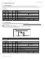
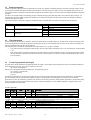
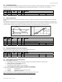
1
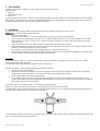
ACC Anti-sweat controller User manual LEGGI E CONSERVA QUESTE ISTRUZIONI READ AND SAVE THESE INSTRUCTIONS IMPORTANT WARNINGS CAREL bases the development of its products on decades of experience in HVAC, on the continuous investments in technological innovations to products, procedures and strict quality processes with in-circuit and functional testing on 100% of its products, and on the most innovative production technology available on the market. CAREL and its subsidiaries nonetheless cannot guarantee that all the aspects of the product and the software included with the product respond to the requirements of the final application, despite the product being developed according to start-of-the-art techniques. The customer (manufacturer, developer or installer of the final equipment) accepts all liability and risk relating to the configuration of the product in order to reach the expected results in relation to the specific final installation and/or equipment. CAREL may, based on specific agreements, acts as a consultant for the positive commissioning of the final unit/application, however in no case does it accept liability for the correct operation of the final equipment/system. The CAREL product is a state-of-the-art product, whose operation is specified in the technical documentation supplied with the product or can be downloaded, even prior to purchase, from the website www.carel.com. Each CAREL product, in relation to its advanced level of technology, requires setup / configuration / programming / commissioning to be able to operate in the best possible way for the specific application. The failure to complete such operations, which are required/indicated in the user manual, may cause the final product to malfunction; CAREL accepts no liability in such cases. Only qualified personnel may install or carry out technical service on the product. The customer must only use the product in the manner described in the documentation relating to the product. In addition to observing any further warnings described in this manual, the following warnings must be heeded for all CAREL products: • Prevent the electronic circuits from getting wet. Rain, humidity and all types of liquids or condensate contain corrosive minerals that may damage the electronic circuits. In any case, the product should be used or stored in environments that comply with the temperature and humidity limits specified in the manual. • Do not install the device in particularly hot environments. Too high temperatures may reduce the life of electronic devices, damage them and deform or melt the plastic parts. In any case, the product should be used or stored in environments that comply with the temperature and humidity limits specified in the manual. • Do not attempt to open the device in any way other than described in the manual. • Do not drop, hit or shake the device, as the internal circuits and mechanisms may be irreparably damaged. • Do not use corrosive chemicals, solvents or aggressive detergents to clean the device. • Do not use the product for applications other than those specified in the technical manual. All of the above suggestions likewise apply to the controllers, serial boards, programming keys or any other accessory in the CAREL product portfolio. CAREL adopts a policy of continual development. Consequently, CAREL reserves the right to make changes and improvements to any product described in this document without prior warning. The technical specifications shown in the manual may be changed without prior warning. The liability of CAREL in relation to its products is specified in the CAREL general contract conditions, available on the website www.carel.com and/or by specific agreements with customers; specifically, to the extent where allowed by applicable legislation, in no case will CAREL, its employees or subsidiaries be liable for any lost earnings or sales, losses of data and information, costs of replacement goods or services, damage to things or people, downtime or any direct, indirect, incidental, actual, punitive, exemplary, special or consequential damage of any kind whatsoever, whether contractual, extra-contractual or due to negligence, or any other liabilities deriving from the installation, use or impossibility to use the product, even if CAREL or its subsidiaries are warned of the possibility of such damage. Disposal of the parts of the controller: INFORMATION FOR USERS ON THE CORRECT HANDLING OF WASTE ELECTRICAL AND ELECTRONIC EQUIPMENT (WEEE) In reference to European Union directive 2002/96/EC issued on 27 January 2003 and the related national legislation, please note that: 1. WEEE cannot be disposed of as municipal waste and such waste must be collected and disposed of separately; 2. The public or private waste collection systems defined by local legislation must be used. In addition, the equipment can be returned to the distributor at the end of its working life when buying new equipment. 3. The equipment may contain hazardous substances: the improper use or incorrect disposal of such may have negative effects on human health and on the environment; 4. The symbol (crossed-out wheeled bin) shown on the product or on the packaging and on the instruction sheet indicates that the equipment has been introduced onto the market after 13 August 2005 and that it must be disposed of separately; 5. In the event of illegal disposal of electrical and electronic waste, the penalties are specified by local waste disposal legislation Contents: 1. Introduction........................................................................................................................................................................................................ 7 1.1 1.2 Models available.................................................................................................................................................................................................................................................7 Main features........................................................................................................................................................................................................................................................7 2. User interface.................................................................................................................................................................................................... 8 3. Installation .......................................................................................................................................................................................................... 8 4. Programming the instruments .............................................................................................................................................................. 10 4.1 5. Default settings................................................................................................................................................................................................................................................. 10 Accessories ..................................................................................................................................................................................................... 11 5.1 5.2 6. Parameter copying key............................................................................................................................................................................................................................... 11 RS485 serial interface board.................................................................................................................................................................................................................. 11 Description of the functions ................................................................................................................................................................... 12 6.1 6.2 6.3 6.4 6.5 6.6 6.7 6.8 6.9 7. Dewpoint calculation .................................................................................................................................................................................................................................... 12 Anti-sweat control........................................................................................................................................................................................................................................... 12 Master management .................................................................................................................................................................................................................................... 13 Slave management ....................................................................................................................................................................................................................................... 13 PI control (proportional and integral)................................................................................................................................................................................................ 13 Overriding the output ................................................................................................................................................................................................................................... 14 Phase control modes ................................................................................................................................................................................................................................... 14 Automatic adaptation to the mains frequency ........................................................................................................................................................................... 14 Alarm situations and alarm management ..................................................................................................................................................................................... 14 Description of the operating parameters......................................................................................................................................... 16 7.1 8. Summary table of operating parameters ....................................................................................................................................................................................... 23 Tables of alarms and signals ................................................................................................................................................................. 25 8.1 8.2 9. Alarms..................................................................................................................................................................................................................................................................... 25 Signals.................................................................................................................................................................................................................................................................... 25 Supervision ...................................................................................................................................................................................................... 26 10. 10.1 10.2 10.3 Specifications and connections ...................................................................................................................................................... 27 Electrical specifications .............................................................................................................................................................................................................................. 27 Connections........................................................................................................................................................................................................................................................ 28 Dimensions and assembly....................................................................................................................................................................................................................... 28 ACC –Anti-sweat controller 1. Introduction The ACC device is a microprocessor controller that prevents the formation of condensate on cold surfaces by measuring the ambient dewpoint and heating the cold surface so as to keep it at a higher temperature than the dewpoint. The heating is performed by controlling the voltage applied to special heaters, using the phase control output on the device. 1.1 Models available Two models are available. The first is a controller complete with RS485 serial interface. The second features a socket for an optional RS485 serial interface board. ACC0082100 Anti-sweat controller with RS485; ACC0082000 Anti-sweat controller with fitting for RS485 option. 1.2 Main features Power supply The supply is 230 Vac mains, 50/60 Hz. Operation is adapted automatically to the mains frequency. Appearance and ergonomics The device has been designed so as to also allow outdoor installation, with specific protection against water and dust guaranteed by the case. Dewpoint measurement The dewpoint is automatically calculated according to the ambient humidity and temperature, measured by special probe/probes. Manual setting or configuration by parameter The operation of the ACC controller can be set as follows: manually, using the trimmers and dipswitches (restricted to the main functions); using the internal parameters (via programming key or serial line). In the first case, the main functions are available for the simple use of the controller and setting by non-specialist personnel. In the second case, the available functions are increased considerably, allowing maximum operating flexibility. External alarm management/on-off signal This is used to force the output to a preset value or to enable/disable operation when a protector is activated or upon receiving an external control signal. PI control (proportional and integral) This function combines normal proportional control with an integral action that, if correctly set based on the specific operating conditions, allows more accurate temperature control. Master/Slave mode This function is used to create small networks of anti-sweat controllers, configuring one controller as the Master, which calculates the dewpoint and then sends this value to the others controllers connected in the network and configured as Slaves. This means that just one humidity and room temperature probe can be used for the entire network. Serial connection An RS485 serial output is available for connection via two wires plus shield to the supervisor or telemaintenance network that support the Carel supervisor protocol or for the construction of Master/Slave networks. Phase control function The control of the power section can be modified to adapt it to the type of load. Index of protection The gasket inside and the materials used to make the case guarantee the controller IP43 index of protection, which can be increased to IP54 when using suitable cable glands and cables. Fastening The device is fastened using 4 screws. CE mark/Electromagnetic compatibility The ACC controller is compliant with the EU standards on electromagnetic compatibility, while quality and safety are ensured by the CAREL ISO 9001 certified design and production system and by the CE mark on the product. Code +030220751 – Rel. 1.2 – 09/10/07 7 ACC –Anti-sweat controller 2. User interface The status of the controller is displayed using LEDs that are only visible with the cover open. The LEDs indicate: power on; serial connection status; alarm status. To set the operation of the controller, 1 trimmer and 4 dipswitches are available for the main functions, while internal parameters are used to set all the other functions. The parameters can be set using the programming key, while access to the parameters for display and setting, as well as access to the variables that represent the status of the controller, is available via serial line. 3. Installation To install the controller, proceed as follows, with reference to the connection diagrams shown at the end of the manual. IMPORTANT: 230 Vac mains voltage present on the board. 1. Connect the power supply: Fit a 10A T (or lower rating) fuse in the power supply line (live L), based on the maximum current expected. 2. Connect the probes and control signals: the probes can be installed at a maximum distance of 10 m from the controller, as long as cables with a minimum cross-section of 1 mm2 are used. To improve immunity to disturbance, use shielded cables (connect just one end of the shield to the earth). 3. Program the instrument: for a more detailed description see the chapter “Programming the instruments”. 4. Connect the actuators: the actuators should only be connected after having programmed the controller. In this regard, the maximum current indicated in the “technical specifications” must be considered. If the controller is used in residential environments (IEC-EN55014-1) a shielded cable must be used. 5. Connect to the serial network: the controller is fitted with a connector for housing a serial interface board, FCSER00000, for connection to the supervisor network. Use a shielded cable with the shield connected to GNX. WARNINGS: The controller must be installed so as to ensure normal cooling, according to the flow of air. Normally, if there are no cooling fans, it is installed vertically, with the cable outlets downwards. The temperature of the surface the control is mounted on must not exceed 70° C. The index of protection is guaranteed only if the following precautions are heeded: • only use one cable in each cable gland • perforate the membrane of the cable gland based on the diameter of the cable used; to ensure tightness, the hole must be significantly smaller than the diameter of the cable used. Use the pre-cut sections on the membrane where possible • pass the cable through the cable gland, ensuring tightness • if the installation requires more than one cable in the same cable gland or cables with a smaller diameter than the hole made, it is the installer’s responsibility to guarantee the appropriate index of protection; for example, using a sheath to increase the thickness or to hold the cables together, making sure there are not gaps. The maximum length of the connection cables is 10 m except where specified otherwise. Size the cross-section of the power wires based on the current input of the load and the length of the cables. If a shielded cable is used to connect the load, both ends of the shield should be earthed. On the controller side, the shield should be earthed using a metal cable clamp screwed to the earth bar before the terminals (Fig.3.a). Fig. 3.a To ensure compliance with the safety standards, the electrical system must be fitted with a suitable switch or disconnector (compliant with standards IEC 60947-1 and IEC 60947-3), located near the appliance. Code +030220751 – Rel. 1.2 – 09/10/07 8 ACC –Anti-sweat controller If the appliance is used in a manner that is not specified by the manufacturer, the protection featured for the appliance may be compromised and the appliance may be seriously damaged. Avoid assembling the controllers in environments with the following characteristics: relative humidity greater than 90% non-condensing; strong vibrations or knocks; exposure to continuous water sprays; exposure to aggressive or pollutant atmospheres (e.g. sulphur or ammonia fumes, saline mist, smoke) so as to avoid corrosion and oxidisation; strong magnetic and/or radio interference (for example, near transmitting antennae); exposure of the controllers to direct sunlight or the elements in general. Observe the following warnings when connecting the controllers: The incorrect connection of the power supply may seriously damage the system. Use cable ends suitable for the corresponding terminals. Loosen each screw and insert the cable ends, then tighten the screws and slightly tug the cables to check that they are sufficiently tight; to tighten the screws, do not use automatic screwdriver, or alternatively adjust to a torque of less than 50 Ncm. If spring terminals are used, compress the spring using a screwdriver, insert the stripped wire then release the spring and slightly tug the cables to check that they are sufficiently tight. Separate as much as possible (at least 3 cm) the signal cables from the cables carrying inductive loads and power cables to avoid possible electromagnetic disturbance. Never lay power cables (including the electrical cables) and probe signal cables in the same conduits. Do not install the probe cables in the immediate vicinity of power devices (contactors, circuit breakers or similar). Reduce the path of the probe cables as much as possible, and avoid spiral paths that enclose power devices. Remember that the NTC temperature probes do not have polarity, and therefore the order the ends are connected is indifferent. CLEANING THE INSTRUMENT. When cleaning the instrument do not use ethyl alcohol, hydrocarbons (petrol), ammonia and derivatives. Use neutral detergents and water. Code +030220751 – Rel. 1.2 – 09/10/07 9 ACC –Anti-sweat controller 4. Programming the instruments The instruments are programmed by dipswitches and trimmer, and by setting the internal parameters accessible via programming key or via serial line. The functions that can be set manually are shown in the tables below: Dipswitch Dip1 Select Master/Slave mode Dip2 Select serial connection mode, Supervisor/LAN Dip3 Select Trimmer mode (Master only) Dip4 Select digital input ID1 mode Trimmer SET OFF: ON: OFF: ON: OFF: ON: OFF: ON: Function Manual offset Configuration ID1=External alarm (Dip4 OFF) ID1=External enabling signal (Dip4 ON) Master Slave Supervisor LAN local manual offset LAN manual offset external alarm external enabling signal range 0.0 – “OFST par.” °C Status of input ID1 Open Closed Open Closed Description Alarm not active alarm active Controller enabled Controller disabled, output 0% Digital input ID1 is normally open by default. A parameter can be set to change the operating logic and manage it as a normally closed contact, in which case the meaning of “Open” and “Closed” must be reversed. 4.1 Default settings The functions that are available by setting the parameters are mostly disabled by default, as they need to be set based on the specific application. Offset setting by trimmer Differential setting Digital input ID1 Digital input ID1 Output in the event of alarms Master/Slave mode Supervisor/LAN mode Trimmer mode PI control Phase control function Output ramp Output linearisation Code +030220751 – Rel. 1.2 – 09/10/07 from 0 to 5°C 2°C external alarm (modifiable by dipswitch) Normally open 100% Master (modifiable by dipswitch) Supervisor (modifiable by dipswitch) Local offset (modifiable by dipswitch) inactive short impulse 5 seconds active 10 ACC –Anti-sweat controller 5. Accessories 5.1 Parameter copying key Programming key PSOPZKEY00/A0 The programming keys PSOPZKEY00 (Figure 5.1.a) and PSOPZKEYA0 (Figure 5.1.b) are used to copy the complete set of parameters relating to the CAREL ACC controller parameters. The keys must be connected to the PROG KEY connector (4 pin AMP) fitted on the controllers, and work even without switching the controller on (see the summary diagram in Figure 5.1.c.). Fig. 5.a Fig. 5.b Fig. 5.c Two functions are available, and are selected by using the two supplied dipswitches; these can be accessed by removing the battery cover: - load the parameters for a controller onto the key (UPLOAD - Fig. 5.1.d); - copy from the key to a controller (DOWNLOAD - Fig. 5.1.e); Warning: the parameters can only be copied between instruments with the same code and compatible software release. The UPLOAD operation can, however, always be performed. The following operations are used for the UPLOAD and/or DOWNLOAD functions, simply by changing the settings of the dipswitches on the key: - open the rear cover on the key and position the 2 dipswitches according to the desired operation; - close the rear cover on the key and insert the key in the connector on the controller; - press the button and check the LED: red for a few seconds, then green, indicates that the operation was completed correctly. Other signals or the flashing of the LED indicates that problems have occurred: refer to the table below; - at the end of the operation, release the button, after a few seconds the LED goes OFF; - remove the key from the controller. LED signal Red LED flashing Green LED flashing Red/green LED flashing (orange signal) Red and green LEDs on Red LED on steady LEDs off Cause Batteries discharged at start copy Batteries discharged during copy or at end of copy Instrument not compatible Error in data being copied Data transfer error Batteries disconnected Meaning and solution The batteries are discharged, the copy operation cannot be performed. Replace the batteries. During the copy operation or at the end of the operation the battery level is low. Replace the batteries and repeat the operation. The parameter set-up cannot be copied as the connected controller model is not compatible. This error only occurs for the DOWNLOAD function; check the code of the controller and run the copy only for compatible codes. Error in the data being copied. The instrument's EEPROM is corrupted, and therefore the key cannot be copied. The copy operation was not completed due to a serious error when transferring or copying the data. Repeat the operation, if the problem persists check the key connections. Check the batteries. Table 5.a 5.2 RS485 serial interface board The RS485 serial interface option (FCSER00000) shown in Figure 5.2.a is used to connect the instrument to the RS 485 serial network for supervision. Figures 5.2.b and 5.2.c show the assembly of the interface in the instrument. Observe the correct polarity of the connector, making sure the protrusion on the serial board matches the notch on the controller, without forcing the board. Fig. 5.2..a Code +030220751 – Rel. 1.2 – 09/10/07 Fig. 5.2.b 11 Fig. 5.2.c ACC –Anti-sweat controller 6. Description of the functions 6.1 Dewpoint calculation The dewpoint is only calculated in Master mode, based on values measured by the humidity and room temperature probes B1 and B2. In Slave mode, the dewpoint is updated via serial by the Master or by the external supervisor and probes B1 and B2 are ignored (the inputs can be disconnected). Associated parameters name range def. ADG1 ADG2 FILT Carel spv var I8 I9 I11 90 to 110 90 to 110 0 to 13 ADO1 ADO2 DEWP PB1H PB2T PB1A PB2A A5 A6 A8 A21 A22 D23 D24 -20.0 to 20.0 -10.0 to 10.0 -50.0 to +99.9 0.0 to 100.0 -50.0 to +90.0 0/1 0/1 6.2 100 100 6 res. UOM. 1% 1% 1 description Probe B1 gain Probe B2 gain Probe filter 0.0 0.0 R/W R R R R 0.1% 0.1°C 0.1°C 0.1rH 0.1°C 1 1 Probe B1 offset Probe B2 offset Dewpoint Humidity probe B1 reading Temperature probe B2 reading Probe B1 fault alarm Probe B2 fault alarm 0= minimum filter 13= maximum filter 0=inactive 0=inactive 1=active 1=active Anti-sweat control The output is controlled according to the temperature measured by probe B3, as shown in the figure. The set point is calculated automatically, adding an offset to the dewpoint that is equal to the value set by parameter plus the value set by trimmer( if any), plus the differential. The end scale of the trimmer is settable by parameter. The output can be disabled if the temperature measured by probe B3 exceeds a limit value, set by parameter. The maximum value of the output can be reduced by parameter. OUT 100% max diff offs Dew-point Trimmer SET Function Manual offset setpoint t(B3) °C Range 0.0 – “OFST par.” °C Associated parameters name range def. MAX ADG3 FILT Carel spv var I4 I10 I11 10 to 100 90 to 110 0 to 13 OFFS DIFF OFST TMAX ADO3 PB3T TRIM SETP PB3A A1 A2 A3 A4 A7 A23 A24 A25 D25 -20.0 to 20.0 0.0 to 20.0 0.0 to 20.0 0.0 to 50.0 -10.0 to 10.0 -50.0 to +90.0 0.0 to 20.0 -50.0 to +90.0 0/1 Code +030220751 – Rel. 1.2 – 09/10/07 100 100 6 res. UOM 1% 1% 1 description Maximum output Probe B3 gain Probe filter 0.0 2.0 5.0 30.0 0.0 R R R R 0.1°C 0.1°C 0.1°C 0.1°C 0.1°C 0.1°C 0.1°C 0.1°C 1 Dewpoint offset Differential End scale offset set by trimmer (0.0 = trimmer disabled) Temperature limit Probe B3 offset Temperature probe B3 reading Reading offset by trimmer Set point calculated\ Probe B3 fault alarm 0=inactive 0= minimum filter 13= maximum filter 12 1=active ACC –Anti-sweat controller 6.3 Master management In Master configuration, all three probes are required (B1, B2 and B3). The dewpoint is calculated according to the values measured by probes B1 and B2. The output is controlled according to the value read by probe B3. In the event of alarms on probes B1 or B2, the dewpoint value is forced to 99.9. If the serial connection is configured as LAN, the Master also becomes the network master and sends the value of the dewpoint calculated to any Slaves connected. The value is set at regular intervals in broadcasting mode, thus without needing to define how many Slaves are connected and their addresses. The dewpoint value sent, when suitably configured by dipswitch, can be increased by the value of an offset set by trimmer, thus allowing simultaneous control of all the Slaves connected. If the serial connection is configured as Supervisor, the Master becomes a network slave and responds to the queries from the Supervisor. Dipswitch Dip1 Select Master/Slave mode Dip2 Select serial connection mode, Supervisor/LAN Dip3 Select Trimmer mode (Master only) 6.4 OFF: ON: OFF: ON: OFF: ON: Master Slave Supervisor LAN local manual offset LAN manual offset Slave management In Slave configuration, the value of the dewpoint is received via network (from a controller configured as the LAN master or from the supervisor, which in turn reads the value from a controller configured as the Supervisor master), and consequently probes B1 and B2 do not need to be connected. The output is controlled according to value read by probe B3. If the dewpoint value is not received via the network or the value received is 99.9, an alarm is activated. • If the serial connection is configured as LAN, the Slave does not respond when broadcasting mode is used. The timeout for no data reception is 10 s. o If the serial connection is configured as Supervisor, the Slave responds even when broadcasting mode is used, however generating a conflict with any other Slaves connected to the LAN. The timeout for no data reception is 20 minutes. For Slaves controlled by Master, Dip2 must be in the ON position. 6.5 PI control (proportional and integral) In addition to the normal contribution of proportional control, the output is also controlled using the integral time on the error (deviation between the value measured and set point). This is used to reduce the error to zero. out = Kp*err + Ki*Integral(err) where err=error, Kp=proportional gain, Ki=integral gain, Ti=integral time, given by: err = (set point – measurement) Kp = max. output/diff Ki = Kp/Ti By definition the integral time is the time required, when the error if constant, for the integral part to have the same contribution as the proportional part. The integral time can be set by parameter (default 10 minutes). The contribution of the integral part can be reduced so as to avoid the phenomenon of “wind-up” (default 50%), however in this case the error will not be removed in steady operation. Special care is required when setting the Ti, as excessively short times (see the inertia of the system) may lead to instability. For a more detailed explanation of integral control, see the documents available on control theory. Associated parameters name INTT AWUP EPIR Carel spv var I6 I7 D1 range def. 1 to 30 0 to 100 0/1 10 50 0 res. UOM 1min 1% 1 description Integral time for PI control Limitation of the integral action (antiwind-up) Enable PI control (Integral) 0=disabled 1=enabled To simplify the fine-tuning of the parameters, some variables that are available that describe the control status in terms of the various components: OUTP OUTI OUTR ERRR I31 I32 I33 A26 -255 to 255 -255 to 255 0 to 255 -200.0 to 200.0 R R R R 1 1 1 0.1°C proportional component (255 = 100%) integral component (255 = 100%) controller output (255 = 100%) control error (set point – b3) The values are expressed with the maximum resolution possible (8 bits plus sign), therefore the value 255 corresponds to 100%. Code +030220751 – Rel. 1.2 – 09/10/07 13 ACC –Anti-sweat controller 6.6 Overriding the output The output can forced to the desired value required at any time via serial line, irrespective of the value calculated by the controller. This function is temporary and is not saved; it is disabled automatically when the data reception timeout elapses: 10 s if DIP2 ON, 20 min if DIP2 OFF. Associated parameters name Carel spv var range def. res. UOM OUTV I14 0 to 100 R/W 1% EOVR D15 0/1 0 1 6.7 description Read/override output Enable override output 0=disabled 1=enabled Phase control modes By default control is based on short impulses. Alternatively, control can be enabled for long impulses (control is maintained until the end of the half period). The displacement of the phase control function can also be changed with reference to the zero-crossing of the mains voltage, so as to adapt it to the cosϕ of the load. The linearisation of the output RMS voltage can also be enabled, rather than use the traditional sinusoidal relationship between phase control and voltage. Finally, the instant variation in the output can be limited so as to optimise operation, and limit peak current. Voltage(RMS) output 100% ELIN on ELIN off Phase delay @ 100% output 100% 0% OUTV Associated parameters name Carel spv var range def. STEP DLPL ELIN ELPL I12 I13 D2 D3 0 to 10 0 to 100 0/1 0/1 5 0 1 0 6.8 res. UO M 1sec 1% 1 1 description Output ramp (minimum time for variation from 0% to 100%) Phase displacement: 100% corresponds to 90° Enable output linearisation 0=disabled Enable long impulse phase control 0=disabled 1=enabled 1=enabled Automatic adaptation to the mains frequency At power-on the mains frequency is measured so as to adapt operation to 50Hz or 60Hz The status of the mains frequency reading is accessible via serial line. name OKHZ STHZ 6.9 Carel spv var D26 D27 range def. 0/1 0/1 R R res. UOM 1 1 description mains frequency reading status mains frequency 0=no ok 0=50Hz 1=ok 1=60Hz Alarm situations and alarm management Alarm status is activated in the event of: external alarm (or in any case, closing of the contact connected to the digital input configured as the alarm input) fault on probes B1, B2 or B3 in master configuration fault on probe B3 in slave configuration interruption to the serial connection in slave configuration error reading/writing the parameters saved in non-volatile memory (EEPROM) The alarm status is signalled by the red LED, depending on the causes, in order of priority: on steady parameter alarm 1 impulse probe alarm or serial connection interruption 2 impulses digital alarm input closed In the event of more than one alarm at the same time, the signal with the highest priority is shown. Warning: if digital input ID1 is set as normally closed, the alarm is active when ID1 is open Code +030220751 – Rel. 1.2 – 09/10/07 14 ACC –Anti-sweat controller The probe fault alarm is generated if the probe is disconnected or short-circuited. In alarm status, the controller output provides one of three possible voltage values, which can be set by parameter: 0%; 50% of the maximum output set by parameter; 100% of the maximum output set by parameter (default). Normal operation is restored automatically as soon as the alarm situation is resolved. In the event of alarms due to errors when reading/writing the parameters, the parameters take the default values. The alarm is reset only when a correct parameter copy operation is performed using the key or the parameters are written from the supervisor. If the alarm persists, the EEPROM is faulty. Dipswitch Dip4 Select digital input ID1 mode OFF: ON: external alarm external enabling signal Associated parameters name range def. ALMO Carel spv var I5 0 to 2 2 res. UOM 1 MOID STID ALRM EEPA ELAN D4 D17 D22 D28 D29 0/1 0/1 0/1 0/1 0/1 1 R R R R 1 1 1 1 1 Code +030220751 – Rel. 1.2 – 09/10/07 description output in alarm status operating logic of digital input ID1 status of digital input ID1 alarm status parameter error alarm serial connection alarm 15 0=0% 1=50% MAX 2=100% MAX 0=normally closed 0=open 0=inactive 0=inactive 0=inactive 1=normally open 1=closed 1=active 1=active 1=active ACC –Anti-sweat controller 7. Description of the operating parameters MAC type of unit type and Carel supervisor address integer var. 1 (read only) resolution and unit of measure 1 range 143 default 143 Non-modifiable parameter used to identify the type of controller in supervision network connections or when connected to the programming key. REL software release type and Carel supervisor address integer var. 2 (read only) resolution and unit of measure 1 range 0 to 255 default -Non-modifiable parameter used to identify the software version installed on the controller. The least significant digit is used to identify functional variations that do not imply changes to the parameter structure. The parameters can only be copied using the programming key between two controllers if the REL parameter has the same value or differs only as regards the least significant digit (for example: the parameters can be copied between controllers with REL 12 and 14, while they cannot be copied between controllers with REL 12 and 20). SADR serial address type and Carel supervisor address integer var. 3 resolution and unit of measure 1 range 1 to 255 default 1 Parameter used to identify the individual controller, so as to make it accessible within the supervision network. MAX maximum output type and Carel supervisor address integer var. 4 resolution and unit of measure 1% range 10 to 100 default 100 Parameter used to set the maximum output value of the controller. Expressed as a % of the mains voltage. ALMO output in alarm status type and Carel supervisor address integer var. 5 resolution and unit of measure 1 range 0 to 2 default 2 Parameter used to set the value of the output in the event of alarms. ALMO=0 output at 0% ALMO=1 output at 50% ALMO=2 output at 100% INTT integral time type and Carel supervisor address integer var. 6 resolution and unit of measure 1min range 1 to 30 default 10 Parameter used to set the intensity of the integral action in PI control. Only used if PI control is enabled. AWUP integral action limit type and Carel supervisor address integer var. 7 resolution and unit of measure 1% range 0 to 100 default 50 Parameter used to limit the contribution of the integral action in PI control, with the purpose of avoiding excessive overshoot and delays in the controlled value, in systems whose inertia cannot be accurately defined in advance and therefore when the control function is hard to calibrate (DIFF and INTT). Only used if PI control is enabled. Code +030220751 – Rel. 1.2 – 09/10/07 16 ACC –Anti-sweat controller ADG1 probe B1 gain type and Carel supervisor address integer var. 8 resolution and unit of measure 1% range 90 to 100 default 100 Parameter used to adjust the value of the probe connected to input B1 using the gain of the measurement amplifier. Effective measurement = (measurement x ADG1)/100. The value calculated can also added to an offset defined by parameter ADO1. ADG2 probe B2 gain type and Carel supervisor address integer var. 9 resolution and unit of measure 1% range 90 to 100 default 100 Parameter used to adjust the value of the probe connected to input B2 using the gain of the measurement amplifier. Effective measurement = (measurement x ADG2)/100. The value calculated can also added to an offset defined by parameter ADO2. ADG3 probe B3 gain type and Carel supervisor address integer var. 10 resolution and unit of measure 1% range 90 to 100 default 100 Parameter used to adjust the value of the probe connected to input B3 using the gain of the measurement amplifier. Effective measurement = (measurement x ADG3)/100. The value calculated can also added to an offset defined by parameter ADO3. FILT probe measurement filter type and Carel supervisor address integer var. 11 resolution and unit of measure 1 range 0 to 13 default 6 Parameter used to set the way the values measured by the probes are filtered. The values shown are typical and may change according to the mode set (CPU workload). FILT=0 FILT=1 FILT=2 FILT=3 FILT=4 FILT=5 FILT=6 FILT=7 FILT=8 FILT=9 FILT=10 FILT=11 FILT=12 FILT=13 time const. (s) 0 0 0.15 0 0.3 0 0.6 0.6 1.2 1.2 2.4 2.4 5 10 meas. update (s) 0.08 0.15 0.08 0.3 0.15 0.6 0.3 0.15 0.6 0.3 0.6 0.3 0.6 0.6 meas./average 8 16 8 32 16 64 32 16 64 32 64 32 64 64 STEP output ramp type and Carel supervisor address integer var. 12 resolution and unit of measure 1s range 0 to 10 default 5 Parameter used to set the minimum time for the variation of the output from 0% to 100% and vice-versa. DLPL phase displacement type and Carel supervisor address integer var. 13 resolution and unit of measure 1 range 0 to 100 default 0 Parameter used to set the displacement in the phase control function with reference to the zero crossing of the mains voltage. Used to optimise the voltage to the load, adapting the displacement to the cosϕ of the load. The maximum value of 100 corresponds to a displacement of around 90°. The output should be forced to 100% and parameter DLPL set accordingly to reach the maximum voltage output. For resistive loads (cosϕ=1), the displacement should be set to zero. Code +030220751 – Rel. 1.2 – 09/10/07 17 ACC –Anti-sweat controller OUTV read/override output type and Carel supervisor address integer var. 14 resolution and unit of measure 1% range 0 to 100 default Variable used to read the output value and, if the Override function is enabled, to override it. This variable can only be written if parameter EOVR=1. OUTP proportional component reading type and Carel supervisor address integer var. (read only) 31 resolution and unit of measure 1 range -255 to 255 default -Variable used to read the value of the proportional component calculated by the control algorithm. OUTP=ERRR*Kp where Kp is the proportional gain defined by Kp=(maxOUT)/Differential The value read is the actual value used in the algorithm, expressed in 8 bits plus sign, therefore 255 corresponds to 100% of the maximum output voltage. OUTI integral component reading type and Carel supervisor address integer var. (read only) 32 resolution and unit of measure 1 range -255 to 255 default -Variable used to read the value of the integral component calculated by the control algorithm. OUTI=Ki*Integral(ERRR)=Integral(Ki*ERRR) where Ki is the integral gain defined by Ki=Kp/Ti where Ti is the integral time (parameter INTT) The value calculated is in any case limited, as an absolute value, by the AWUP parameter.. The value read is the actual value used in the algorithm, expressed in 8 bits plus sign, therefore 255 corresponds to 100% of the maximum output voltage. OUTR output reading type and Carel supervisor address integer var. (read only) 33 resolution and unit of measure 1 range 0 to 255 default -Variable used to read the overall value of the output calculated by the control algorithm. During control, this value is the sum of the components OUTP and OUTI, limited between 0 and 255. In the event of active alarms or other conditions that force the output to a preset value, OUTR is not calculated as shown previously, but rather reflects the preset value. If the Override function is enabled, OUTR maintains its normal value, even if the output is set by the OUTV parameter. The value read is the actual value used in the algorithm, expressed in 8 bits plus sign, therefore 255 corresponds to 100% of the maximum output voltage. OFFS dewpoint offset type and Carel supervisor address analogue var. 1 resolution and unit of measure 0.1°C range -20.0 to 20.0 default 0.0 Parameter used to set an offset for the dewpoint measured and consequently increase or decrease the working set point. The effective offset also depends on the value set using the SET trimmer and the settings of the dipswitches. DIFF differential type and Carel supervisor address resolution and unit of measure range default Parameter used to set the value of the control differential. Code +030220751 – Rel. 1.2 – 09/10/07 analogue var. 2 0.1°C 0.0 to 20.0 2.0 18 ACC –Anti-sweat controller OFST SET trimmer end scale type and Carel supervisor address analogue var. 3 resolution and unit of measure 0.1°C range 0.0 to 20.0 default 5.0 Parameter used to set the end scale of the SET trimmer and as a consequence the maximum field of variation for the manually settable offset. The effective offset also depends on the value set using the OFFS parameter and the settings of the dipswitches. TMAX maximum temperature limit type and Carel supervisor address analogue var. 4 resolution and unit of measure 0.1°C range 0.0 to 90.0 default 30.0 Parameter used to set the maximum temperature value measured by probe B3 beyond which the output is disabled. ADO1 probe B1 offset type and Carel supervisor address analogue var. 5 resolution and unit of measure 0.1% rH range -10.0 to 10.0 default 0.0 Parameter used to adjust the value read by the probe connected to input B1 using the offset of the measurement amplifier. Effective measurement = (measurement x ADG1)/100 + ADO1). ADO2 probe B2 offset type and Carel supervisor address analogue var. 6 resolution and unit of measure 0.1°C range -10.0 to 10.0 default 0.0 Parameter used to adjust the value read by the probe connected to input B2 using the offset of the measurement amplifier. Effective measurement = (measurement x ADG2)/100 + ADO2). ADO3 probe B3 offset type and Carel supervisor address analogue var. 7 resolution and unit of measure 0.1°C range -10.0 to 10.0 default 0.0 Parameter used to adjust the value read by the probe connected to input B3 using the offset of the measurement amplifier. Effective measurement = (measurement x ADG3)/100 + ADO3). DEWP dewpoint type and Carel supervisor address analogue var. 8 resolution and unit of measure 0.1°C range -50.0 to 99.9 default -Variable that depending on the operating mode set represents the dewpoint calculated or used. Master mode: read only variable that represents the value calculated based on the values read by probes B1 and B2 and used for control the value is forced to 99.9 in the event of alarms on probes B1 or B2 the value is sent in broadcasting mode via serial line if LAN mode is selected Slave mode: read/write variable sent via serial line used for control the failed update of the dewpoint or reception of the value 99.9 causes an alarm PB1H probe B1 reading type and Carel supervisor address analogue var. (read only) 21 resolution and unit of measure 0.1% rH range 0.0 to 100.0 default -Variable used to read the humidity value in rH measured by probe B1. Code +030220751 – Rel. 1.2 – 09/10/07 19 ACC –Anti-sweat controller PB2T probe B2 reading type and Carel supervisor address analogue var. (read only) 22 resolution and unit of measure 0.1°C range -50.0 to 90.0 default -Variable used to read the temperature value in °C measured by probe B2. PB3T probe B3 reading type and Carel supervisor address analogue var. (read only) 23 resolution and unit of measure 0.1°C range -50.0 to 90.0 default -Variable used to read the temperature value in °C measured by probe B3. TRIM SET trimmer reading type and Carel supervisor address analogue var. (read only) 24 resolution and unit of measure 0.1°C range 0 to ”OFST” par. default -Variable used to read the offset value set manually by trimmer. The effective offset also depends on the value set using the OFFS parameter and the settings of the dipswitches. SETP set point calculated reading type and Carel supervisor address resolution and unit of measure range default Variable used to read the value of the set point calculated. analogue var. (read only) 25 0.1°C -50.0 to 90.0 -- ERRR error reading type and Carel supervisor address analogue var. (read only) 26 resolution and unit of measure 0.1°C range -200.0 to 200.0 default -Variable used to read the value of the error (difference between the set point and the measurement of the controlled value B3) calculated by the control algorithm and based on which the proportional and integral components are calculated. The error is equal to: error= B3 reading-set point EPIR enable PI control type and Carel supervisor address digital var. 1 resolution and unit of measure 1 range 0 /1 default 0 Parameter used to enable PI control (proportional + integral). EPIR=0 disabled EPIR=1 enabled ELIN enable output linearisation type and Carel supervisor address digital var. 2 resolution and unit of measure 1 range 0 /1 default 1 Parameter used to enable the linearisation of the output voltage, compensating the sinusoidal relationship between phase and voltage. ELIN=0 disabled ELIN=1 enabled ELPL select phase control function type and Carel supervisor address digital var. 3 resolution and unit of measure 1 range 0 /1 default 0 Parameter used to select the type of phase control.. ELPL=0 short impulse (around 3 ms) ELPL=1 impulse long (from the moment of switching until the end of the mains half period) Code +030220751 – Rel. 1.2 – 09/10/07 20 ACC –Anti-sweat controller MOID operating logic of ID1 type and Carel supervisor address digital var. 4 resolution and unit of measure 1 range 0 /1 default 1 Parameter used to select the operating logic of digital input ID1. MOID=0 normally closed MOID=1 normally open EOVR enable Override function type and Carel supervisor address digital var. 15 resolution and unit of measure 1 range 0 /1 default 0 Variable used to enable the Override function and consequently force the output to the value defined by the OUTV parameter, irrespective of the value calculated by the control algorithm: EOVR=0 disabled EOVR=1 enabled The variable is forced to zero (Override disabled) on power-up and in any case when the serial line data reception timeout elapses: 10 s if DIP2 ON, 20 min if DIP2 OFF. FDEF reset parameter default values type and Carel supervisor address resolution and unit of measure range default Variable used to reset the default values of the parameters. digital var. 16 1 0 /1 0 FDEF=0 FDEF=1 no action reset default The value is automatically set back to 0 when the function is activated. It is not saved in the EEPROM. STID input ID1 status type and Carel supervisor address resolution and unit of measure range default Variable used to read the status of digital input ID1. STID=0 STID=1 digital var. (read only) 17 1 0 /1 -- open closed STD1 dipswitch 1 status type and Carel supervisor address resolution and unit of measure range default Variable used to read the position of dipswitch 1. STD1=0 STD1=1 digital var. (read only) 18 1 0 /1 -- Off On STD2 dipswitch 2 status type and Carel supervisor address resolution and unit of measure range default Variable used to read the position of dipswitch 2. STD2=0 STD2=1 digital var. (read only) 19 1 0 /1 -- Off On STD3 dipswitch 3 status type and Carel supervisor address resolution and unit of measure range default Variable used to read the position of dipswitch 3. STD3=0 Off STD3=1 On Code +030220751 – Rel. 1.2 – 09/10/07 digital var. (read only) 20 1 0 /1 -- 21 ACC –Anti-sweat controller STD4 dipswitch 4 status type and Carel supervisor address resolution and unit of measure range default Variable used to read the position of dipswitch 4. STD4=0 Off STD4=1 On digital var. (read only) 21 1 0 /1 -- ALRM alarm status type and Carel supervisor address digital var. (read only) 22 resolution and unit of measure 1 range 0 /1 default -Variable used to read the status of the alarm. ALRM=0 inactive ALRM=1 active The alarm may be signalled externally, associated with the digital input, or due to a fault on probes B1 or B2. PB1A probe B1 alarm status type and Carel supervisor address digital var. (read only) 23 resolution and unit of measure 1 range 0 /1 default -Variable used to read the status of the probe B1 fault alarm. PB1A=0 inactive PB1A =1 active The alarm is activated automatically if the value read by probe B1 is outside of the range of possible values, typically due to disconnection or shortcircuit. The alarm is not detected if slave mode is selected. PB2A probe B2 alarm status type and Carel supervisor address digital var. (read only) 24 resolution and unit of measure 1 range 0 /1 default -Variable used to read the status of the probe B2 fault alarm. PB2A=0 inactive PB2A =1 active The alarm is activated automatically if the value read by probe B2 is outside of the range of possible values, typically due to disconnection or shortcircuit. The alarm is not detected if slave mode is selected. PB3A probe B3 alarm status type and Carel supervisor address digital var. (read only) 25 resolution and unit of measure 1 range 0 /1 default -Variable used to read the status of the probe B3 fault alarm. PB3A=0 inactive PB3A =1 active The alarm is activated automatically if the value read by probe B3 is outside of the range of possible values, typically due to disconnection or short-circuit. OKHZ mains frequency reading status type and Carel supervisor address digital var. (read only) 26 resolution and unit of measure 1 range 0 /1 default -Variable used to read the status relating to the reading of the mains frequency. OKHZ=0 reading in progress OKHZ =1 reading completed At the end of the reading, the variable STHZ signals the frequency, 50 or 60Hz. Code +030220751 – Rel. 1.2 – 09/10/07 22 ACC –Anti-sweat controller STHZ mains frequency type and Carel supervisor address digital var. (read only) 27 resolution and unit of measure 1 range 0 /1 default -Variable used to read the mains frequency detected by the controller. STHZ=0 50Hz STHZ=1 60Hz The value of the variable is only meaningful after the mains frequency has been read by the controller (see parameter OKHZ). EEPA invalid parameter alarm status type and Carel supervisor address digital var. (read only) 28 resolution and unit of measure 1 range 0 /1 default -Variable used to read the status of the parameter read/write error alarm. EEPA=0 inactive EEPA =1 active ELAN LAN connection alarm status type and Carel supervisor address digital var. (read only) 29 resolution and unit of measure 1 range 0 /1 default -Variable used to read the status of the alarm relating to the interruption of the serial connection. ELAN=0 inactive ELAN =1 active The alarm is disabled in master mode. 7.1 Summary table of operating parameters name MAC REL SADR MAX ALMO add. I1 I2 I3 I4 I5 range 143 0 to 255 1 to 255 10 to 100 0 to 2 def. R R 1 100 2 User value - res. UOM 1 1 1 1% 1 description Type of unit FW release Serial address (note 1) Maximum output Output in alarm status INTT AWUP ADG1 ADG2 ADG3 FILT I6 I7 I8 I9 I10 I11 1 to 30 0 to 100 90 to 110 90 to 110 90 to 110 0 to 13 10 50 100 100 100 6 1min 1% 1% 1% 1% 1 Integral time in PI control Limitation of the integral action (antiwind-up) Probe B1 gain Probe B2 gain Probe B3 gain 0= minimum filter Probe filter 5 0 R/W R R R R R 1sec 1% 1% Output ramp (minimum time for variation from 0% to 100%) Phase displacement: 100% corresponds to 90° Read/Override output (NOTE 2) not used proportional component (255 = 100%) integral component (255 = 100%) controller output (255 = 100%) not used 0=0% 1=50% MAX 2=100% MAX 13= maximum filter STEP DLPL OUTV OUTP OUTI OUTR OFFS DIFF OFST TMAX ADO1 ADO2 ADO3 I12 0 to 10 I13 0 to 100 I14 0 to 100 I15 to I30 0 I31 -255 to 255 I32 -255 to 255 I33 0 to 255 I34 to I50 0 A1 A2 A3 A4 A5 A6 A7 -20.0 to 20.0 0.0 to 20.0 0.0 to 20.0 0.0 to 50.0 -20.0 to 20.0 -10.0 to 10.0 -10.0 to 10.0 Code +030220751 – Rel. 1.2 – 09/10/07 0.0 2.0 5.0 30.0 0.0 0.0 0.0 - 1 1 1 0.1°C 0.1°C 0.1°C 0.1°C 0.1% 0.1°C 0.1°C Dewpoint offset Differential End scale for offset set by trimmer (0.0 = trimmer disabled) Temperature limit Probe B1 offset Probe B2 offset Probe B3 offset 23 ACC –Anti-sweat controller name DEWP PB1H PB2T PB3T TRIM SETP ERRR EPIR ELIN ELPL MOID EOVR FDEF STID STD1 STD2 STD3 STD4 ALRM PB1A PB2A PB3A OKHZ STHZ EEPA ELAN add. range A8 -50.0 to +99.9 A9 to 0 A20 A21 0.0 to 100.0 A22 -50.0 to +90.0 A23 -50.0 to +90.0 A24 0.0 to “OFST” A25 -50.0 to +90.0 A26 -200.0 to 200.0 A14 to 0 A40 D1 D2 D3 D4 D5 to D14 D15 D16 D17 D18 D19 D20 D21 D22 D23 D24 D25 D26 D27 D28 D29 D30 to D32 def. R/W R User value - res. UOM 0.1°C R R R R R R R - 0.1rH 0.1°C 0.1°C 0.1°C 0.1°C 0.1°C 0/1 0/1 0/1 0/1 0 0 1 0 1 R - 0/1 0/1 0/1 0/1 0/1 0/1 0/1 0/1 0/1 0/1 0/1 0/1 0/1 0/1 0/1 0 0 0 R R R R R R R R R R R R R R - description Dewpoint (NOTE 3) not used Humidity probe B1 reading Temperature probe B2 reading Temperature probe B3 reading Offset by trimmer reading Set point calculated Control error (set point – B3) not used 1 1 1 1 Enable PI control (Integral) Enable output linearisation Enable long impulse phase control Operating logic of digital input ID1 not used 0=disabled 0=disabled 0=disabled 0=normally closed 1=enabled 1=enabled 1=enabled 1=normally open 1 1 1 1 1 1 1 1 1 1 1 1 1 1 1 Enable override output (NOTE 2) Reset default values (NOTE 4) digital input ID1 status dipswitch 1 status dipswitch 2 status dipswitch 3 status dipswitch 4 status alarm status probe B1 fault alarm probe B2 fault alarm probe B3 fault alarm mains freq. reading status mains frequency parameter error alarm serial connection alarm not used 0=disabled 0=no action 0=open 0=Off 0=Off 0=Off 0=Off 0=inactive 0=inactive 0=inactive 0=inactive 0=no ok 0=50Hz 0=inactive 0=inactive 1=enabled 1=enabled 1=closed 1=On 1=On 1=On 1=On 1=active 1=active 1=active 1=active 1=ok 1=60Hz 1=active 1=active A indicates analogue variables I indicates integer variables D indicates digital variables R indicates read only variables (no default values, as these are initialised/updated automatically at power-on) NOTE 1: The parameter should be modified via serial connection with care, as this implies the dynamic management of the address by the Supervisor. NOTE 2: The override control is disabled at power-on and when serial communication is interrupted for more than 10 seconds. NOTE 3: The value 99.9 is used by the Master to signal to the Slaves that the correct of the dewpoint cannot be calculated due to humidity alarm or room temperature probes. NOTE 4: The value is automatically set back to 0 when a command is received. Code +030220751 – Rel. 1.2 – 09/10/07 24 ACC –Anti-sweat controller 8. Tables of alarms and signals 8.1 Alarms The alarm status is indicated by the red LED status of the red LED off on flashing 1 impulse flashing 2 impulses description no alarm parameter error alarm probe alarm (Master) probe or LAN connection alarm (Slave) external alarm possible causes of alarm non-volatile memory error (EEPROM) probes disconnected or short-circuited probes disconnected or short-circuited, or failed update of the dewpoint via LAN closing of the contact connected to the digital input The status of the digital input that activates the external alarm depends on the operating logic set (by default normally open) If there are multiple alarms activated at the same time, the first in order shown in the table is signalled. The active alarm status forces the output to the value defined by the ALMO parameter. The alarm status is available via serial line. 8.2 Signals Power is signalled by the green LED. The status of the serial connection is signalled by the yellow LED. status of the yellow LED off description connection deactivated flashing on data reception connection active possible causes cable disconnected supervisor off-line protocol not supported await data reception from Master or Supervisor data reception in progress the connection is active, but no data has been received for less than 10 s The serial connection is automatically deactivated 10 seconds after the last valid data is received. If the Master is in LAN serial mode (Dip 1 and Dip 2 = ON), the yellow LED has the following meaning: on flashing connection active data transmission Code +030220751 – Rel. 1.2 – 09/10/07 the connection is active, but no data is being sent the Master is sending data to the slaves connected to the LAN 25 ACC –Anti-sweat controller 9. Supervision Carel supervisor protocol ver 3.0s is supported (19200 baud). To set the addresses of the individual variables, see the column “Carel spv var” in the table of parameters. The variables are grouped into blocks: if a variable in a certain block is modified, the entire block is sent down. Integer variables relating to parameters I1 – I14 Integer status variables I31 – I33 Analogue variables relating to parameters A1 – A8 Analogue status variables A21 – A26 Digital variables relating to parameters D1 – D4 Digital status variables/commands D15 – D29 If an external supervisor is used with a network of Master and Slave controllers, the supervisor is responsible for reading the value of the dewpoint calculated by the Master and sending it to the various Slaves connected. The supervisor can manage the network in standard mode, that is, assigning each Slave the specific network address, or alternatively in broadcasting mode, in which case the address of the Slave does not need to be assigned, however this does not allow the possibility to read the status of the Slave. Code +030220751 – Rel. 1.2 – 09/10/07 26 ACC –Anti-sweat controller 10. Specifications and connections 10.1 Electrical specifications Power supply Analogue outputs Analogue inputs 230 Vac single-phase, -15% +10% 50/60 Hz 1 phase control 0 to 230 Vac single-phase, 8 A (min 500 mA) 1 input for 0 to 10 V humidity probes (Rin: 20 k ) precision 5% (typical 2%), excluding the probes 2 inputs for std Carel NTC temp. probes (10 k @25 °C) range of measurement: –50T90 °C precision 1°C [-10T50]; 2°C [-40T-10 and 50T90], excluding the probes Digital inputs 1 input for voltage-free contact typical voltage 12 V with the contact open, typical current 6 mA with the contact closed. Serial ports 1 standard two wire RS485 connector (only on some models) CAREL supervisor protocol; baud rate 19200; max length 1 km with shielded cable Light signals Green power LED Red alarm LED Yellow serial connection LED (flashing during valid data reception) Controller setting 1 trimmer for manually setting the offset 4 dipswitches Terminals and connectors Power supply and analogue outputs: Screw terminals for cable cross-section min. 2.5 mm2 max 4 mm2. Signals: Spring terminals for cable cross-section min. 1.5 mm2 max 2.5 mm2. 4 pin JST connector for the programming key Operating conditions -10T50 °C, <90% RH non-condensing Storage conditions -20T70 °C, <90% RH non-condensing Index of protection IP43 (can reach IP54) Environmental pollution Normal Protection against electric shock Class I PTI of the insulating materials 250 V Period of stress across the insulating parts Long Type of action -disconnection 1C Category of resistance to heat and fire Category D (UL94 – V0) Immunity against voltage surges Category 1 Ageing characteristics 60,000 operating hours No. of automatic operating cycles 100,000 Software class and structure Class A Case Metallic (Al) with plastic cover (75°C ball pressure test) Dimensions 140x135x90 mm Assembly Metallic case fastened to the panel or wall using 4 screws dia. 3.5/4 mm Certification EMC: EN 61326-1, EN 55014-1, EN 55014-2 Safety: EN 60730-1 Code +030220751 – Rel. 1.2 – 09/10/07 27 ACC –Anti-sweat controller 10.2 Connections Offset Trimmer LEDs PROG. KEY 230 V~ Fig. 10.a L, N L1, N ID1, GND B1, GND, +V B2, GND B3, GND GNX, RXTX+, RXTX- 230 Vac power supply input 230 Vac power supply output to load Programmable digital input. Alarm or external enabling signal, see dipswitch configuration. 0 to 10 V analogue input for ambient humidity probe reading. NTC analogue input 10 k•@25 °C for room temperature probe reading. NTC analogue input 10 k•@25°C for control temperature probe reading. RS485 serial (FCSER0000 option required). 10.3 Dimensions and assembly Fig. 10.b Code +030220751 – Rel. 1.2 – 09/10/07 28 NOTES: __________________________________________________________________________________________________ _________________________________________________________________________________________________________ _________________________________________________________________________________________________________ _________________________________________________________________________________________________________ _________________________________________________________________________________________________________ _________________________________________________________________________________________________________ _________________________________________________________________________________________________________ _________________________________________________________________________________________________________ _________________________________________________________________________________________________________ _________________________________________________________________________________________________________ _________________________________________________________________________________________________________ _________________________________________________________________________________________________________ _________________________________________________________________________________________________________ _________________________________________________________________________________________________________ _________________________________________________________________________________________________________ _________________________________________________________________________________________________________ _________________________________________________________________________________________________________ _________________________________________________________________________________________________________ _________________________________________________________________________________________________________ _________________________________________________________________________________________________________ _________________________________________________________________________________________________________ _________________________________________________________________________________________________________ _________________________________________________________________________________________________________ _________________________________________________________________________________________________________ _________________________________________________________________________________________________________ _________________________________________________________________________________________________________ _________________________________________________________________________________________________________ _________________________________________________________________________________________________________ _________________________________________________________________________________________________________ _________________________________________________________________________________________________________ _________________________________________________________________________________________________________ NOTES: __________________________________________________________________________________________________ _________________________________________________________________________________________________________ _________________________________________________________________________________________________________ _________________________________________________________________________________________________________ _________________________________________________________________________________________________________ _________________________________________________________________________________________________________ _________________________________________________________________________________________________________ _________________________________________________________________________________________________________ _________________________________________________________________________________________________________ _________________________________________________________________________________________________________ _________________________________________________________________________________________________________ _________________________________________________________________________________________________________ _________________________________________________________________________________________________________ _________________________________________________________________________________________________________ _________________________________________________________________________________________________________ _________________________________________________________________________________________________________ _________________________________________________________________________________________________________ _________________________________________________________________________________________________________ _________________________________________________________________________________________________________ _________________________________________________________________________________________________________ _________________________________________________________________________________________________________ _________________________________________________________________________________________________________ _________________________________________________________________________________________________________ _________________________________________________________________________________________________________ _________________________________________________________________________________________________________ _________________________________________________________________________________________________________ _________________________________________________________________________________________________________ _________________________________________________________________________________________________________ _________________________________________________________________________________________________________ _________________________________________________________________________________________________________ _________________________________________________________________________________________________________ “ACC” +030220751 - rel. 1.2 – 09/10/07 CAREL S.p.A. Via dell’Industria, 11 - 35020 Brugine - Padova (Italy) Tel. (+39) 049.9716611 Fax (+39) 049.9716600 http://www.carel.com - e-mail: [email protected]