1
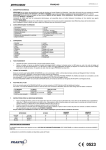
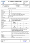
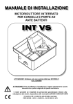
®
gate automations
Rf33
COPPIA DI FOTOCELLULE DA ESTERNO CON
ALIMENTAZIONE A BATTERIA INCLUSA
COUPLE OF EXTERNAL PHOTOCELLS
WITH BATTERY INCLUDED POWER SUPPLY
Manuale d’Installazione e d’Uso
Manuel d'Installation et Utilisation.
Installation and use manual
Handbuch der Installation und des Gebrauchs
Manual de Uso e Instalación
RF33_06.doc
ITALIANO
RF33
1.
DESCRIZIONE GENERALE
Le fotocellule RF33 sono dotate di un trasmettitore con la possibilità di essere alimentato mediante due batterie da 3V6 2,7Ah al LitioCloruro di Tionile oppure mediante alimentazione esterna 12/24Vac/dc, selezionabile mediante un jumper.
La Fotocellula dispone di un morsetto per il collegamento del contatto di una sicurezza esterna (costa meccanica) ed è
particolarmente adatta per essere impiegata sui cancelli scorrevoli, montata sulla parte mobile, consentendo il collegamento di una
costa meccanica a filo, senza dover stendere cavi o dover utilizzare cavi riavvolgibili.
La durata delle batterie è superiore a 15 mesi.
Conforme agli standard Europei di riferimento (Compatibilità Elettromagnetica 89/336/CEE).
2.
APPLICAZIONI
Su cancelli scorrevoli o su automazioni in genere dove sia richiesto il minor numero possibile di cablaggi (ad esempio impianti già
esistenti in cui si vogliono aggiungere delle sicurezze).
3.
CARATTERISTICHE TECNICHE PRINCIPALI
Alimentazione TX
2 Batterie Litio Cloruro di Tionile 3V6 2,7Ah
In alternativa 12 ÷ 24 V ac/dc
Alimentazione RX
12 ÷ 24 V ac/dc
Consumo TX
< 500 ìA
Consumo RX
30 mA
Contenitore
ABS
Dimensioni/peso
110 x 50 x 25 mm 200g
Grado d'isolamento
IP 45
Lunghezza d’onda infrarosso
950 nm
Portata contatto relè
0,5 A @ 24 Vac/dc
Portata fascio infrarosso
25 m nominali (8 m in esterno )
Temperatura di funzionamento
-20 +55° C
Tempo
d’intervento
con < 40 ms
interruzione raggio fotocellula
Tempo
d’intervento
con < 60 ms
azionamento bordo sensibile
collegato in morsettiera
Tempo di ripristino
< 120 ms
4.
5.
+12 ÷ +24 VAC/DC
0V
EDGE
EDGE
1 2 3 4 5
Alimentazione 12 - 24 Vac/dc
Comune d’alimentazione
Contatto normalmente chiuso relè
Comune contatto relè
Contatto normalmente aperto relè
J2: Selezione
alimentazione
J1: Morsettiera
per contatto costa
meccanica
B
Fig. 1B
(TX)
1 2 3 4
MORSETTIERA TRASMETTITORE
1
2
3
4
6.
+12 ÷ +24 VAC/DC
0V
N.C.
C
N.A.
1 2 3 4 5
A
MORSETTIERA RICEVITORE
1
2
3
4
5
Fig. 1A
(RX)
Alimentazione 12 - 24 Vac/dc
Comune alimentazione
Morsetto per contatto costa sensibile
Morsetto per contatto costa sensibile
INSTALLAZIONE
Fissare le fotocellule servendosi delle dime di foratura in dotazione (fig.2)
Eseguire i collegamenti come indicato nei paragrafi precedenti, avendo cura di selezionare l’alimentazione del trasmettitore
tramite l’apposito jumper (J2, Fig. 1B):
POSIZIONE A: alimentazione esterna 12 -24 VAC/DC
POSIZIONE B: alimentazione a batteria
Collegare all’apposita morsettiera (J1, Fig. 1B) il contatto di uscita della costa o della sicurezza esterna al trasmettitore. Se
questa opzione non viene utilizzata, lasciare inserito il ponticello esistente.
-
-
Effettuare l’allineamento del fascio al ricevitore agendo sulle apposite viti di fissaggio “A” (fig. 2) fornite in dotazione sia sul
ricevitore che sul trasmettitore.
Misurare con un voltmetro il valore di tensione presente sui test-point del ricevitore (fig. 3). Tale valore varia in funzione di vari
parametri, tra cui la distanza tra le fotocellule. Più alto è il valore di tensione sul test- point migliore è l’allineamento. La misura
ottimale deve comunque essere compresa tra 0,5 e 0,6 Vcc.
Verificare che l’interruzione del fascio infrarosso generi l’apertura del contatto normalmente chiuso del relè sul ricevitore e
l’accensione del LED rosso.
PROTECO S.r.l.
Via Neive, 77
12050 Castagnito (CN)
ITALY
Tel. +39 0173 210111
Fax +39 0173 210199
www.proteco.net
[email protected]
RF33_06.doc
ENGLISH
RF33
1.
GENERAL DESCRIPTION
In the photocell RF33 the transmitter can be powered with two 3.6V 2.7Ah Lithium-Tionyle Chloride batteries or with an external
power supply at 12-24 VACDC, selectable with a jumper.
The photocell has two terminals in which the output contact of a safety device (e.g. a rubber edge) can be connected, and it is
particularly suitable to be used in sliding gates, mounted on the moving wing, allowing to connect the edge safety device without
long cables or self-winding cables.
Battery life is more than 15 months.
The photocell is manufactured in compliance with the European directive 89/336/EEC (EMC).
2.
APPLICATIONS
In sliding gates or other kinds of installations where cables cannot be used or must be reduced (e.g. in existing installations where a
safety device must be added)
3.
MAIN TECHNICAL FEATURES
Power supply (TX)
Power supply (RX)
Consumption (TX)
Consumption (RX)
Enclosure
Size / Weight
Degree of insulation
Infrared wavelength
Relay contact capacity
Infrared beam range
Working temperature
Intervention time
Restore time
4.
2 x 3.6V 2.7Ah Lithium-Tionyle Chloride batteries
or external 12 ÷ 24 V ac/dc
12 ÷ 24 V ac/dc
< 500 ì A
30 mA
ABS
110 x 50 x 25 mm 200g
IP 45
950 nm
0,5 A @ 24 V ac/dc
25 m nominal (8 m in external use )
-20 +70° C
< 40 ms
< 120 ms
RECEIVER TERMINALS
1
2
3
4
5
+12 ÷ +24 VAC/DC
0V
N.C.
C
N.A.
Fig. 1A
(RX)
1 2 3 4 5
1 2 3 4 5
Power supply 12 - 24 V ac/dc
Common supply
Relay contact normally closed
Common relay contact
Relay contact normally open
A
J2: Power supply
selection
J1: Terminals
for safety edge
contact
1 2 3 4 5
B
5.
Fig. 1B
(TX)
TRANSMITTER TERMINALS
1 2 3 4
1
2
3
4
6.
+12 ÷ +24 VAC/DC
0V
EDGE
EDGE
Power supply 12 - 24 V ac/dc
Common supply
Terminal for safety edge contact
Terminal for safety edge contact
INSTALLATION
Fix the photocell by using the supplied templates (fig.2)
Connect the wires as described in paragraphs 4 and 5 and select the source of power supply with the relevant jumper (J2, fig
1B):
POSITION A: external power supply 12-24 VAC/DC
POSITION B: battery
-
-
Connect the output contact of the safety edge (or other safety devices) to the relevant terminals (J1, fig. 1B). If this option is
not used, don’t remove the existing short-circuit jumper.
Align the beam with the receiver using the relevant adjustment screws “A” (fig. 2) on the receiver and transmi tter.
Measure with a voltmeter the voltage at the receiver test-points (fig.3). This value may change according to various
parameters, among which the distance between the photocells. The higher the voltage value at the test-points, the better the
alignment. Optimum voltage should be between 0,5 and 0,6 VDC.
Interruption of the infrared beam must generate opening of the normally closed contact of the relay on the receiver and lighting
up of the red LED.
PROTECO S.r.l.
Via Neive, 77
12050 Castagnito (CN)
ITALY
Tel. +39 0173 210111
Fax +39 0173 210199
www.proteco.net
[email protected]
RF33RF33_06.doc
FRANÇAIS
RF33
1.
DESCRIPTION GÉNÉRALE
Les photocellules FT33 sont dotées d'un émetteur qui peut être alimenté par deux batteries 3,6V 2,7Ah au lithium - chlorure de
thionyle ou par alimentation externe 12/24Vca/cc, sélectionnable par cavalier.
La photocellule dispose d'une borne pour la connexion du contact d'une sécurité externe (bord sensible) et est particulièrement
indiquée pour une utilisation sur des portails coulissants, installée sur la partie mobile, permettant ainsi la connexion d'un bord
sensible à fil, sans avoir à tirer de câbles ou à utiliser de câbles enroula
bles.
La durée de la batterie est supérieure à 15 mois.
Conforme aux standards européens (Compatibilité Electromagnétique 89/336/CEE).
2.
APPLICATIONS
Sur les portails coulissants ou sur les automatismes en général, nécessitant le moins possible de câblages (par exemple, sur des
installations existantes où l'on veut ajouter des sécurités).
3.
CARACTÉRISTIQUES TECHNIQUES PRINCIPALES
Alimentation TX
Alimentation RX
Consommation TX
Consommation RX
Boîtier
Dimensions/poids
Degré d’isolation
Longueur d’onde infrarouge
Capacité contact relais
Portée faisceau infrarouge
Température de fonctionnement
Temps d’intervention
Temps de restauration
4.
2 batteries Lythium – Tyonile Chloride 3.6V, 2.7 Ah
ou 12 ÷ 24 VAC/DC
12 ÷ 24 VAC/DC
< 500 ìA
30 mA
ABS
110 x 50 x 25 mm 200g
IP 45
950 nm
0,5 A @ 24 V ac/dc
25 m nominaux (8 m en extérieur )
-20 +55° C
< 40 ms
< 120 ms
Fig. 1A
(RX)
1 2 3 4 5
J2: Selection
alimentation
BOITE A BORNES RÉCEPTEURS
1
2
3
4
5
+12 ÷ +24 VAC/DC
0V
N.C.
C
N.A.
Alimentation 12 - 24 Vac/dc
Commun d’alimentation
Contact normalement fermé relais
Commun contact relais
Contact normalement ouvert relais
A
J1: Borne pour le
contact du bord
sensible
B
5.
BOITE A BORNES ÉMETTEUR
1
2
3
4
6.
+12 ÷ +24 VAC/DC
0V
EDGE
EDGE
Alimentation 12 - 24 Vac/dc
Commun alimentation
Borne pour le contact du bord sensible
Borne pour le contact du bord sensible
1 2 3 4
Fig. 1B
(TX)
INSTALLATION
Fixer les photocellules à l'aide des gabarits de perçage fournis (fig.2).
Effectuer les connexions comme indiqué dans les paragraphes précédents, en veillant à sélectionner l'alimentation de l'émetteur
au moyen du cavalier (J2, Fig. 1B):
POSITION A: alimentation externe 12-24 VCA/CC
POSITION B: alimentation par batterie
Relier à la borne (J1, Fig. 1B) le contact de sortie du bord de sécurité. Si cette option n'est pas utilisée, laisser activé le cavalier
existant.
Effectuer l’alignement du faisceau au récepteur en agissant sur les vis de réglage « A » (fig. 2) prévues à cet effet, présentes
aussi bien sur le récepteur que sur l’émetteur.
La vérification de l’alignement se fait en mesurant avec un voltmètre la valeur de tension présente sur le test-point du récepteur
(fig. 3). Cette valeur varie en fonction des différents paramètres au nombre desquels la distance entre les cellules
photoélectriques. Plus élevée est la valeur de la tension sur le test-point, meilleur est l’alignement. La tension optimale se situe
entre 0,5 et 0,6 Vcc.
L’interruption du faisceau infrarouge génère l’ouverture du contact normalement fermé du relais sur le récepteur et l’allumage
de la LED rouge.
PROTECO S.r.l.
Via Neive, 77
12050 Castagnito (CN)
ITALY
Tel. +39 0173 210111
Fax +39 0173 210199
www.proteco.net
[email protected]
RF33_06.doc
DEUTSCH
RF33
1.
ALLGEMEINE BESCHREIBUNG
Die Photozellen RF33 sind mit einem Sender ausgestattet, der mit zwei 3,6V 2,7Ah Lithium-Tionyl-Chlorid-Batterien oder extern mit
12/24V AC/DC, wählbar mittels Jumper, gespeist werden kann.
Die Photozelle verfügt über eine Klemme für den Anschluss des Kontakts einer Außensicherung (Tastrand), ist besonders geeignet
für die Montage auf dem beweglichen Teil von Schiebetoren und erlaubt den Anschluss eines Tastrands aus Draht ohne das
Verlegen von Kabeln oder die Verwendung aufrollbarer Kabel.
Die Lebensdauer der Batterien beträgt mehr als 15 Monate.
In Übereinstimmung mit den europäischen Referenzstandards (Elektromagnetische Verträglichkeit 89/336/CEE).
2.
ANWENDUNGSBEREICHE
Anwendungsbereiche finden sich auf Schiebetoren oder allgemein auf Automationen, wo eine möglichst kleine Anzahl von
Verkabelungen gefordert ist (zum Beispiel bereits bestehende Anlagen, in denen Sicherungen eingebaut werden sollen.
3.
DIE WICHTIGSTEN TECHNISCHEN MERKMALE
Spannungsversorgung TX
Spannungsversorgung RX
Stromaufnahme TX
Stromaufnahme RX
Gehäuse
Abmessungen / Gewicht
Modulationsfrequenz
Schutzgrad
Wellenlänge der Infrarotstrahlen
Belastbarkeit des Relaiskontakts
(Leistung)
Reichweite des Infrarotbündels
Betriebstemperatur
Ansprechzeit
Wiederherstellung Zeit
4.
2 x 3,6V 2,7Ah Lithium-Tionyl-Chlorid-Batterien
oder extern 12/24V AC/DC
12 ÷ 24 V AC/DC
< 500 ì A
30 mA
ABS
110 x 50 x 25 mm 200g
1000 Hz
IP 45
950 nm
0,5 A @ 24 V ac/dc
25 m nominal (8 m im Außenbereich )
-20 +70° C
< 40 ms
< 120 ms
Fig. 1A
(RX)
1 2 3 4 5
Speisung
Auswahl
KLEMMENBRETT EMPFÄNGER
A
1
2
3
4
5
5.
Speisung 12 - 24 Vac/dc
Nulleiter Speisung
Normalerw eise geschlossener Relaiskontakt
Nulleiter Relaiskontakt
Normalerweise geöffneter Relaiskontakt
KLEMMENBRETT SENDER
1
2
3
4
6.
+12 ÷ +24 V ac/dc
0V
N.C.
C
N.A.
+12 ÷ +24 V ac/dc
0V
EDGE
EDGE
J1: Anschlüß
für den Kontakt
des Tastrand
B
1 2 3 4
Speisung 12 - 24 Vac/dc
Nulleiter Speisung
Anschlüß für den Kontakt des Tastrand
Anschlüß für den Kontakt des Tastrand
Fig. 1B
(TX)
FUNKTIONSWEISE
Befestigen Sie die Photozellen unter Verwendung der mitgelieferten Bohrschablonen (Abb. 2)
Stellen Sie die Anschlüsse wie in den oben stehenden Abschnitten beschrieben her. Achten Sie dabei darauf, die Speisung
des Senders mit Hilfe des Jumpers (J2, Abb. 1B) zu wählen:
POSITION A: Außenspeisung 12-24 VAC/DC
POSITION B: Batteriespeisung
Schließen Sie den Ausgangskontakt der Sicherheitsflanke (J1, Abb. 1B) an die vorgesehene Klemmleiste Bei Nichtverwendung
dieser Option lassen sie die vorhandene Brücke eingesetzt.
Führen Sie die Ausrichtung des Bündels auf den Empfänger durch. Betätigen Sie dazu sowohl die Regelschrauben “A” (fig. 2)
am Empfänger als auch am Sender.
Die Ausrichtung wird überprüft, indem mit einem Voltmeter die am Testpunkt des Empfängers anliegende Spannung gemessen
wird (fig.3). Dieser Wert ändert sich in Abhängigkeit verschiedener Parameter, darunter der Abstand zwischen den
Photozellen. Je höher der Spannungswert am Te stpunkt ist, desto besser ist die Ausrichtung. Der optimale Wert muß zwischen
0,5 und 0,6 Vcc Gleichsp liegen.
Die Unterbrechung des Infrarotbündels bewirkt das Öffnen des normalerweise geschlossenen Relaiskontakts auf dem
Empfänger sowie das Aufleuchten der roten Led.
PROTECO S.r.l.
Via Neive, 77
12050 Castagnito (CN)
ITALY
Tel. +39 0173 210111
Fax +39 0173 210199
www.proteco.net
[email protected]
RF33_06.doc
ESPANOL
RF33
1.
DESCRIPCIÓN GENERAL
Las fotocélulas RF33 están dotadas de un transmisor que puede ser alimentado mediante dos baterías de 3,6V-2,7 Ah de litiocloruro de tionilo o mediante alimentación externa 12/24 V ca/cc, seleccionable mediante un puente.
La fotocélula cuenta con un borne para la conexión de un dispositivo de seguridad externo (borde sensible) y es particularmente
apta para ser utilizada en verjas correderas, instalada en la parte móvil, permitiendo la conexión de un borde sensible sin necesidad
de extender cables ni utilizar cables enrollables.
La duración de las baterías es superior a 15 meses.
Conforme a los estándares europeos de referencia (Compatibilidad electromagnética 89/336/CEE).
2.
APLICACIONES
Verjas correderas o automatismos en general que requieren el menor número posible de cables (por ejemplo, sistemas ya
existentes en los que se desea instalar dispositivos de seguridad adicionales).
3.
CARACTERÍSTICAS TÉCNICAS PRINCIPALES
Alimentación TX
Alimentación RX
Consumo TX
Consumo RX
Contenedor
Dimensiones/peso
Grado de aislamiento
Amplitud de onda infrarrojo
Capacidad contacto relé
Capacidad haz infrarrojo
Temperatura de funcionamiento
Tiempo de intervención
Tiempo de restauración
4.
1 2 3 4 5
+12 ÷ +24 V ac/dc
0V
N.C.
C
N.C.
Alimentación 12 - 24V ac/dc
Común de alimentación
Contacto normalmente cerrado relé
Común contacto relé
Contacto normalmente abierto relé
+12 ÷ +24 V ac/dc
0V
EDGE
EDGE
J2: Selección
alimentación
J1: Terminales
para el contacto
del borde
sensible
A
B
TABLERO DE BORNES TRANSMISOR
1
2
3
4
6.
Fig. 1A
(RX)
TABLERO DE BORNES RECEPTOR
1
2
3
4
5
5.
2 baterías de 3,6V-2,7 Ah de litio-cloruro de tionilo
o alimentación externa 12/24 V AC/DC
12 ÷ 24 V AC/DC
< 500 ìA
30 mA
ABS
110 x 50 x 25 mm 200g
IP 45
950 nm
0,5 A @ 24 V ac/dc
25 m nominales (8 m en exterior )
-20 +70° C
< 40 ms
< 120 ms
Alimentación 12 - 24 Vac/dc
Común de alimentación
Terminal para el contacto del borde sensible
Te rminal para el contacto del borde sensible
1 2 3 4
Fig. 1B
(TX)
FUNCIONAMIENTO
Fije las fotocélulas utilizando las plantillas de perforación suministradas (Fig. 2).
Realice las conexiones tal como se describe en los párrafos anteriores, seleccionando la alimentación del transmisor con el
puente (J2, Fig. 1B):
POSICIÓN A: alimentación externa 12-24 V ca/cc
POSICIÓN B: alimentación con batería
Conecte el contacto de salida del perfil de seguridad a la caja de bornes (J1, Fig. 1B). Si no se utiliza esta opción, deje
colocado el puente presente.
Llevar a cabo la alineación del haz al receptor actuando en los tornillos de ajuste correspondientes “A” (fig. 2) que se
encuentran tanto en el receptor como en el transmisor.
La comprobación de la alineación se lleva a cabo midiendo con un voltímetro el valor de tensión presente en el test-point del
receptor (fig. 3). Este valor cambia, en función de los distintos parámetros entre los que destaca la distancia entre las
fotocélulas. Cuanto más alto es el valor de tensión en el test-point mejor será la alineación. El valor optimal es comprendidos
entre 0,5 y 0,6 Vcc.
La interrupción del haz infrarrojo provoca la abertura del contacto normalmente cerrado del relé en el receptor y el encendido
del LED rojo.
PROTECO S.r.l.
Via Neive, 77
12050 Castagnito (CN)
ITALY
Tel. +39 0173 210111
Fax +39 0173 210199
www.proteco.net
[email protected]
RF33_06.doc
RF33
Fig. 2
TX
TEST POINT (0,5 ÷ 0,6 VDC)
RX
A
Fig. 3
TX
RX
TX
PROTECO S.r.l.
Via Neive, 77
12050 Castagnito (CN)
ITALY
Tel. +39 0173 210111
Fax +39 0173 210199
www.proteco.net
[email protected]
RX
AVVERTENZE PER LA SICUREZZA
SAFETY WARNINGS
CONSIGNES DE SECURITE
Le presenti avvertenze sono parti integranti ed
essenziali del prodotto e devono essere
consegnate all'utilizzatore. Leggerle
attentamente in quanto forniscono importanti
indicazioni riguardanti l'installazione, l'uso e la
manutenzione. E' necessario conservare il
presente modulo e trasmetterlo ad eventuali
subentranti nell'uso dell'impianto. L'errata
installazione o l'utilizzo improprio del prodotto
può essere fonte di grave pericolo.
These warnings are an integral and essential
part of the product, and must be delivered to
the user. Read them carefully: they provide
important installation, operating, and
maintenance instructions. Keep this form and
give it to any persons who may use the system
in the future. Incorrect installation or improper
use of the product may cause serious danger.
Les présentes consignes sont une partie
intégrante et essentielle du produit et doivent être
remis à l'utilisateur. Il faut les lire attentivement
car elles fournissent des indications importantes
concernant l'installation, l'utilisation et l'entretien.
Cette notice doit être conservée et remise,
éventuellement, à tout autre utilisateur. Une
mauvaise installation et une utilisation
inappropriée du produit peuvent être à l'origine
de graves dangers.
ISTRUZIONI PER L'INSTALLAZIONE ·
L'installazione deve essere eseguita da
personale professionalmente competente e in
osservanza della legislazione locale, statale,
nazionale ed europee vigente.
·Prima di iniziare l'installazione verificare
l'integrità del prodotto.
·La posa in opera, i collegamenti elettrici e le
regolazioni devono essere effettuati a "Regola
d'arte".I materiali d'imballaggio (cartone, plastica,
polistirolo, ecc.) non vanno dispersi nell'ambiente
e non devono essere lasciati alla portata dei
bambini in quanto potenziali fonti di pericolo.
·Non installare il prodotto in ambienti a pericolo di
esplosione o disturbati da campi
elettromagnetici. La presenza di gas o fumi
infiammabili costituisce un grave pericolo per la
sicurezza.Prevedere sulla rete di alimentazione
una protezione per extratensioni, un
interruttore/sezionatore e/o differenziale
adeguati al prodotto e in conformità alle
normative vigenti.Il costruttore declina ogni e
qualsiasi responsabilità qualora vengano
installati dei dispositivi e/o componenti
incompatibili ai fini dell'integrità del prodotto, della
sicurezza e del funzionamento.Per la riparazione
o sostituzione delle parti dovranno essere
utilizzati esclusivamente ricambi
originali.L'installatore deve fornire tutte le
informazioni relative al funzionamento, alla
manutenzione e all'utilizzo delle singole parti
componenti e del sistema nella sua globalità.
MANUTENZIONE
Per garantire l'efficienza del prodotto è
indispensabile che personale professionalmente
competente effettui la manutenzione nei tempi
prestabiliti dall'installatore, dal produttore e dalla
legislazione vigente.Gli interventi di installazione,
manutenzione, riparazione e pulizia devono
essere documentati. Tale documentazione deve
essere conservata dall'utilizzatore, a
disposizione del personale competente preposto.
AVVERTENZE PER L'UTENTE
·Leggere attentamente le istruzioni e la
documentazione allegata.Il prodotto dovrà
essere destinato all'uso per il quale è stato
espressamente concepito. Ogni altro utilizzo è da
considerarsi
improprio e quindi pericoloso.
Inoltre, le informazioni contenute nel presente
documento e nella documentazione allegata,
potranno essere oggetto di modifiche senza
alcun preavviso. Sono infatti fornite a titolo
indicativo per l'applicazione del prodotto. La
società PROTECO S.r.l. declina ogni ed
eventuale responsabilità. ·Tenere i prodotti, i
dispositivi, la documentazione e quant'altro fuori
dalla portata dei bambini. · I n c a s o d i
manutenzione, pulizia, guasto o cattivo
funzionamento del prodotto, togliere
l'alimentazione, astenendosi da qualsiasi
tentativo d'intervento. Rivolgersi solo al
personale professionalmente competente e
preposto allo scopo. Il mancato rispetto di quanto
sopra può causare situazioni di grave pericolo.
INSTALLATION INSTRUCTIONS
·Installation must be performed by a qualified
professional and must observe all local, state,
national and European regulations.
Before starting installation, make sure that the
product is in perfect condition.
Laying, electrical connections, and
adjustments must be done to "Industry
Standards".
Packing materials (cardboard, plastic,
polystyrene, etc.) are potentially dangerous.
They must be disposed of properly and kept
out of the reach of children ·Do not install the
product in an explosive environment or in an
area disturbed by electromagnetic fields.
The presence of gas or inflammable fumes is a
serious safety hazard.Provide an overvoltage
protection, mains/knife switch and/or
differential on the power network that is
suitable for the product and conforming to
current standards.
·The manufacturer declines any and all liability
if any incompatible devices and/or
components are installed that compromise the
integrity, safety, and operation of the product.
·Only original spares must be used for repair or
replacement of parts.
·The installer must supply all information
regarding the operation, maintenance, and
use of individual components and of the
system as a whole.
MAINTENANCE
·To guarantee the efficiency of the product, it is
essential that qualified professionals perform
maintenance at the times and intervals
required by the installer, by the manufacturer,
and by current law. All installation,
maintenance, repair and cleaning operations
must be documented. The user must store all
such documentation and make it available to
competent personnel.
WARNING FOR THE USER
Carefully read the enclosed instructions and
documentation.
This product must be used for its intended
purpose only. Any other use is improper and
therefore dangerous. The information
contained herein and in the enclosed
documentation may be changed without
notice, and are in fact provided in an
approximate manner for application of the
product. PROTECO S.r.l. declines any and all
liability in this regard.
·Keep this product, devices, documentation
and all other items out of the reach of children.
·In case of maintenance, cleaning, breakdown
or malfunction of this product, turn off the unit
and DO NOT try to repair it yourself. Call a
qualified professional only. Disregard of this
instruction may cause extremely dangerous
situations.
INSTRUCTIONS POUR L'INSTALLATION
L'installation doit être effectuée par du personnel
qualifié, conformément aux normes locales,
régionales, nationales et européennes en
vigueur. Avant de procéder à l'installation, vérifier
l'intégrité du produit.
La mise en oeuvre, les raccordements
électriques et les réglages doivent être effectués
selon les "règles de l'art". Les matériaux
d'emballage (carton, plastique, polystyrène,
etc...) ne doivent pas être jetés dans la nature et
ne doivent pas être laissés à la portée des
enfants car ils peuvent être à l'origine de graves
dangers. Ne pas installer le produit dans des
locaux présentant des risques d'explosion ou
perturbés par des champs électromagnétiques.
La présence de gaz ou de fumées inflammables
constitue un grave danger pour la
sécurité.Prévoir, sur le réseau d'alimentation,
une protection contre les surtensions, un
interrupteur/sectionneur et/ou un différentiel
adaptés au produit, conformément aux normes
en vigueur. Le fabricant décline toute
responsabilité en cas d'installation de dispositifs
et/ou de composants compromettant l'intégrité
du produit, la sécurité et le fonctionnement. Pour
la réparation ou le remplacement des pièces,
utiliser exclusivement des pièces détachées
d'origine.L'installateur doit fournir toutes les
informations relatives au fonctionnement, à
l'entretien et à l'utilisation de chaque élément
constitutif et de l'ensemble du système.
ENTRETIEN
Pour garantir le bon fonctionnement du produit, il
est indispensable que l'entretien soit effectué par
du personnel qualifié, dans les délais indiqués
par l'installateur, par le fabricant et par les
normes en vigueur. Les interventions
d'installation, d'entretien, les réparations et le
nettoyage doivent être documentés. Cette
documentation doit être conservée par
l'utilisateur et mise à la disposition du personnel
qualifié préposé à ces tâches.
AVERTISSEMENTS POUR L'UTILISATEUR
Lire attentivement les instructions et la
documentation ci-jointe.Le produit doit être
destiné à l'usage pour lequel il a été
expressément conçu. Toute autre utilisation est
considérée comme inappropriée et, par
conséquent, dangereuse. En outre, les
informations contenues dans cette notice et dans
la documentation ci-jointe pourront faire l'objet de
modifications sans préavis. En effet, elles sont
fournies à titre indicatif, pour l'application du
produit. La société PROTECO S.r.l. décline toute
responsabilité éventuelle.Garder les produits,
les dispositifs, la documentation et autre hors de
la portée des enfants.En cas d'entretien, de
nettoyage, de panne ou de mauvais
fonctionnement du produit, couper l'alimentation,
en s'abstenant de toute tentative d'intervention.
S'adresser uniquement à du personnel qualifié et
préposé à ces tâches. Le non-respect des
consignes ci-dessus peut causer des situations
de grave danger.
SICHEITSHINWEISE
Dieses Hinweisblatt stellt einen wichtigen und
unverzichtbaren Bestandteil des Produkts dar und muß
dem Anwender ausgehändigt werden. Lesen Sie den
Inhalt bitte aufmerksam durch, da hier wichtige
Informationen betreffend Installation, Bedienung und
Wartung geliefert werden. Das Hinweisblatt muß
sorgfältig aufbewahrt und auch späteren Benutzern
übergeben werden. Fehlerhafte Installation und
unsachgemäßer Gebrauch können schwere Gefahren
hervorrufen.
ADVERTENCIAS PARA LA SEGURIDAD
Las presentes advertencias son partes
integrantes y esenciales del producto y tienen
que ser entregadas al usuario. Hay que leerlas
atentamente ya que ofrecen indicaciones
importantes que se refieren a la instalación, el
uso y la manutención. Es necesario conservar
este módulo y entregarlo a eventuales nuevos
usuarios de la instalación. La instalación
errónea o la utilización indebida del producto
puede ser fuente de grave peligro.
ANLEITUNG ZUR INSTALLATION
·Die Installation muß von qualifiziertem und
kompententem Fachpersonal durchgeführt werden.
Dabei sind die geltenden örtlichen Vorschriften sowie
die staatlichen Gesetze auf nationaler und
europäischer Ebene zu befolgen.
·Überzeugen Sie sich vor dem Beginn mit der
Installation von der Unversehrtheit des Produkts.
Die Inbetriebsetzung, die elektrischen Anschlüsse
sowie die Einstellungen müssen nach "den Regeln der
Kunst" durchgeführt werden. Die
Verpackungsmaterialien (Karton, Plastik, Polystyrol
usw.) dürfen nicht in umweltschädigender Weise
entsorgt werden und sind von Kindern fernzuhalten, da
diese durch die Materialien gefährdet werden können.
Installieren Sie das Produkt nicht in
explosionsgefährdeten Umgebungen oder dort, wo
elektromagnetische Störfelder wirken. Das
Vorhandensein von Gas oder entzündlichen Dämpfen
stellt eine große Gefahr für die Sicherheit dar. ·Das
Versorgungsnetz muß mit einem
Überspannungsschutz ausgestattet werden. Dazu ist
die Installation eines passenden, den geltenden
Vorschriften genügenden (Trenn-) Schalters und/oder
Differentialschalters vorzusehen.Der Hersteller
übernimmt keinerlei Verantwortung für Schäden, die
entstehen aufgrund der Installation mit dem Produkt
nicht verträglicher, das heißt, dieses schädigender
beziehungsweise dessen Betriebssicherheit
g e f ä h r d e n d e r Vo r r i c h t u n g e n u n d / o d e r
Komponenten.Für Reparaturen und Auswechselungen
dürfen ausschließlich Originalersatzteile verwendet
werden.Der Installateur muß alle Informationen zur
Funktionsweise, zur Wartung und zur Bedienung der
einzelnen Komponenten sowie des Systems
insgesamt zur Verfügung stellen.
INSTRUCCIONES PARA LA INSTALACIÓN
·La instalación debe ser llevada a cabo por
personal profesional competente y que tenga
en cuenta la legislación local, estatal, nacional
y europea vigente.Antes de iniciar la
instalación comprobar la integridad del
producto. El emplazamiento, las conexiones
eléctricas y las regulaciones tienen que ser
llevadas a cabo a "Regla de arte".Los
materiales de embalaje (cartón, plástico,
poliestireno, etc.) no deben ser arrojados en el
ambiente y no deben estar al alcance de los
niños ya que pueden ser fuente de peligro. No
instalar el producto en ambientes con peligro
de explosión o afectados por campos
electromagnéticos. La presencia de gas o
humos inflamables constituye un grave peligro
para la seguridad.Prever en la red de
alimentación una protección para
extratensiones, un interruptor / seccionador
y/o diferencial adecuados al producto y
conforme con la normativa vigente.El
constructor declina toda responsabilidad en el
caso de que se instalen dispositivos y/o piezas
incompatibles que afecten a la integridad, la
seguridad y el funcionamiento del producto.
Para la reparación o sustitución de las piezas
será necesario utilizar sólo recambios
originales.El instalador debe facilitar toda la
información relativa al funcionamiento, al
mantenimiento y a la utilización de cada una de
las piezas de que se compone, y del sistema
en su totalidad.
WARTUNG
Zur Gewährleistung der Effizienz des Produkts ist es
unverzichtbar, daß die Instandhaltungsarbeiten von
kompetentem Fachpersonal innerhalb der vom
Installateur, dem Hersteller sowie von der geltenden
Gesetzgebung vorgesehenen Zeiten durchgeführt
werden.Die Eingriffe betreffend Installation, Wartung,
Reparatur und Reinigung müssen dokumentiert
werden. Diese Unterlagen müssen vom Verwender
aufbewahrt und dem zuständigen Personal zur
Verfügung gestellt werden.
HINWEISE AN DEN BENUTZER
·Lesen Sie die beigefügten Anleitungen und Unterlagen
sorgfältig durch.Das Produkt muß für diejenigen
Bereiche eingesetzt werden, für welche es konzipiert
wurde. Jede davon abweichende Verwendung ist als
unzulässig und somit gefährlich zu betrachten. Die in
diesem Dokument sowie in den beigefügten
Unterlagen enthaltenen Informationen können daher
jederzeit ohne Vorankündigung Änderungen
unterzogen werden. Sämtliche Angaben verstehen
sich mithin als Richtwerte für die Anwendung des
Produkts. Die Firma PROTECO lehnt jede weitere
Verantwortung ab.Das Produkt, die Vorrichtungen, die
Unterlagen und alles weitere sind von Kindern
fernzuhalten.Bei Instandhaltungs-oder
Reinigungsarbeiten, Defekten oder Betriebsstörungen
des Produkts die Energieversorgung abtrennen und in
keiner Weise versuchen, Eingriffe vorzunehmen. Für
diese Fälle ist ausschließlich kompetentes
Fachpersonal zuständig. Die Nichteinhaltung dieser
Vorschriften kann zu Situationen großer Gefahr führen.
MANTENIMIENTO
Para garantizar la eficacia del producto, es
indispensable que personal profesional y
competente lleve a cabo el mantenimiento en
los periodos indicados por el instalador, por el
productor y por la legislación vigente.Las
intervenciones de instalación, mantenimiento,
reparación y limpieza tienen que estar
ratificadas por documentos. Estos
documentos deben ser conservados por el
usuario y estar siempre a disposición del
personal competente encargado.
ADVERTENCIAS PARA EL USUARIO
Leer atentamente las instrucciones y la
documentación adjunta.
El producto tiene que ser destinado al uso para
el que ha sido concebido. Otro uso será
considerado impropio y por tanto peligroso.
Además, las informaciones que contiene el
presente documento y la documentación
adjunta, podrán ser objeto de modificaciones
sin previo aviso. Se entregan, de hecho, como
información para la aplicación del producto. La
sociedad PROTECO S.r.l. declina cualquier
responsabilidad.Mantener los productos, los
dispositivos, la documentación y todo lo
demás fuera del alcance de los niños. En caso
de mantenimiento, limpieza, avería o mal
funcionamiento del producto, quitar la
alimentación y no llevar a cabo ninguna
intervención. Dirigirse sólo al personal
profesional y competente encargado para tal
fin. La no observancia de lo anterior puede
causar situaciones de grave peligro.
PROTECO S.r.l
Via Neive, 77
12050 Castagnito (CN)
ITALY
Tel. +39 0173 210111
Fax +39 0173 210199
www.proteco.net
[email protected]
LIMITI DELLA GARANZIA
La garanzia è di 24 mesi decorrenti dalla data del
documento di vendita ed è valida solo per il primo
acquirente
Essa decade in caso di: negligenza, errore o cattivo uso
del prodotto, uso di accessori non conformi alle
specifiche del costruttore, manomissioni operate dal
cliente o da terzi, cause naturali (fulmini, alluvioni,
incendi, ecc.), sommosse, atti vandalici, modifiche delle
condizioni ambientali del luogo d'installazione. Non
comprende inoltre, le parti soggette ad usura (batterie,
ecc..).La restituzione alla PROTECO S.r.l. del prodotto
da riparare deve avvenire in porto franco destinatario. La
PROTECO S.r.l. restituirà il prodotto riparato al mittente
in porto assegnato. In caso contrario la merce verrà
respinta al ricevimento o trattenuta alla spedizione.
L'acquisto del prodotto implica la piena accettazione di
tutte le condizioni della garanzia. Per eventuali
controversi il foro competente è quello di Alba (CN) Italia.
TERMS AND LIMITS OF WARRANTY
L'appareil est garanti 24 mois à compter de la date du
document d'achat et n'est valable que pour le premier
acheteur. La garantie cesse en cas de: négligence,
erreur ou mauvaise utilisation du produit, utilisation
d'accessoires non conformes aux spécifications du
fabricant, altérations effectuées par le client ou par des
tiers, causes naturelles (foudre, inondations, incendies,
etc...), émeutes, actes de vandalisme. Sont également
exclues de la garantie les pièces susceptibles d'usure
(piles, etc...). Le produit à réparer doit être expédié
franco de port à PROTECO S.r.l.. PROTECO S.r.l.
retournera le produit réparé à l'expéditeur en port dû.
Sinon, la marchandise sera refusée ou retenue à
l'expédition. L'achat du produit implique l'acceptation
totale de toutes les conditions de garantie. En cas de
litige, la seule juridiction compétente est le Tribunal de
Alba (CN) - Italie.
LIMITES DE GARANTIE
La garantía es de 24 meses a partir de la fecha impresa
en el documento de venta y es válida sólo para el primer
comprador.
La misma pierde valor en caso de: negligencia, error o
mal uso del producto, uso de accesorios no conformes
con las especificaciones del constructor, daños
producidos por el cliente o por terceros, causas
naturales ( rayos, aluviones, incendios, etc.),
movimientos bruscos, actos vandálicos, modificaciones
de las condiciones ambientales del lugar de instalación.
Además no comprende las piezas sujetas a desgaste (
pilas, etc.). La restitución a la PROTECO S.r.l. del
producto por reparar tiene que llevarse a cabo en puerto
franco del destinatario. La PROTECO S.r.l. restituirá el
producto arreglado al remitente con porte a franquear en
su destino. En caso contrario la mercancía será
rechazada cuando se reciba o retenida cuando se envíe.
La adquisición del producto conlleva que se aceptan
completamente todas las condiciones de garantía. Para
eventuales controversias el tribunal competente es el de
Alba (CN) - Italia.
GARANTIELEISTUNG
This product has a warranty of 24 months starting on the
date of selling document, and is valid for the first
purchaser only.
The warranty will expire in the event of: negligence,
incorrect or improper use of the product, use of
accessories not conforming to the manufacturer's
specifications, tampering by the customer or by third
parties, natural causes (lightning, flood, fire, etc.),
insurrection, acts of vandalism, changes in
environmental conditions of the installation site. In
addition, it does not cover parts subject to wear
(batteries, etc.). If the product has to be returned to
PROTECO S.r.l.. for repair, it must be sent postage paid.
PROTECO S.r.l. will return the repaired product to the
sender COD. Under any other circumstances, the
product will be refused upon receipt or held at the time of
shipment. Purchase of this product implies full
acceptance of all of the terms of this warranty. In the
event of dispute, the competent forum will be that of Alba
(CN), Italy.
LIMITES DE LA GARANTIA
Die Garantie hat eine Dauer von 24 Monaten vom Datum
von der Urkunde von Verkauf und gilt nur für den
Erstkäufer. Die Garantie verfällt unter den folgenden
Bedingungen: Einsatz von Zubehör, welches nicht den
Spezifikationen des Herstellers entspricht,
Manipulationen (Beschädigungen) durch den Kunden
oder Dritte, natürliche Ursachen (Blitzeinschläge,
Überschwemmungen, Brände usw), Aufruhr,
Va n d a l i s m e n s o w i e Ä n d e r u n g e n d e r
Umweltbedingungen am Installationsort. Darüber hinaus
sind Verschleißteile (Batterien usw.) von der
Garantieleistung ausgeschlossen. Zu reparierende
Produkte sind portofrei an die PROTECO S.r.l.
einzusenden. Die Firma PROTECO S.r.l. schickt das
reparierte Produkt gegen Erstattung des Portos an den
Sender zurück. In gegenteiligem Fall wird die Ware nicht
angenommen beziehungsweise vom Versand
zurückgehalten. Mit dem Erwerb des Produkts akzeptiert
der Käufer alle Garantiebedingungen. Im Falle von
Rechtsstreitigkeiten ist der Gerichtsstand Alba (CN) Italien zuständig.
PROTECO S.r.l.
Via Neive, 77
12050 Castagnito (CN)
ITALY
Tel. +39 0173 210111
Fax +39 0173 210199
www.proteco.net
[email protected]
®
gate automations
PROTECO S.r.l.
Via Neive, 77
12050 Castagnito (CN)
ITALY
Tel. +39 0173 210111
Fax +39 0173 210199
www.proteco.net
[email protected]