1
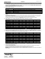
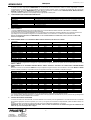
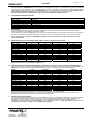
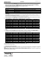
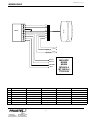
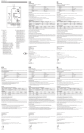
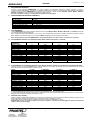
1.
ISMRMAGINOXEU_11_06.doc
ITALIANO
MRMAGINOX
INFORMAZIONI GENERALI
Il lettore di carte magnetiche MRMAGINOX è in grado di leggere le informazioni codificate su banda magnetica in traccia 2,
conformemente agli standard ISO, e di tradurle nei segnali CLOCK e DATA secondo un protocollo largamente impiegato nei sistemi di
controllo accessi. Il lettore MRMAGINOX si interfaccia alle centrali di controllo accessi M2000PE, M3000, M5000, MT4000-2,
MT10000-4, TTD3000 e a tutte le centrali che accettano questo protocollo.
Può essere installato in esterno, se adeguatamente protetto contro la pioggia.
2.
CARATTERISTICHE TECNICHE PRINCIPALI
Standard badge
Metodo di lettura
Alimentazione
Distanza massima di collegamento
Consumo
Velocità di inserimento carta
Vita media
Dimensioni e peso
3.
ISO 7811 traccia 2
F2F (FM)
5÷12 VDC ± 5% (senza convertitore MW30) / 12 VDC ± 5% (con convertitore MW30)
100 m
< 10 mA
125 - 1250 mm/s
> 1.000.000 letture
49 x 82 x 35 (WxHxD) - 336g
COLLEGAMENTI
Il lettore MRMAGINOX può essere collegato direttamente alle centrali M3000, M5000, MT4000-2, MT10000-4 e TTD3000 configurate
con protocollo di lettura di tipo Dataclock.
Per il collegamento alla centrale M2000PE, o nel caso in cui la configurazione dell’impianto richieda di utilizzare il protocollo di lettura
di tipo Wiegand, è necessario interporre il convertitore MW30, collegandolo alla minima distanza dal lettore
Per il collegamento del lettore all’MRMAGINOX è consigliabile utilizzare cavo STP classe 5 o FTP classe 5 o superiore.
3.1 COLLEGAMENTO DIRETTO ALLE CENTRALI M3000, M5000, MT4000-2, MT10000-4 e TTD3000
LETTORE
MRMAGINOX
M3000 – Porta 1
M3000 – Porta 2
M5000 – Porta 1
M5000 – Porta 2
M5000 – Porta 3
M5000 – Porta 4
MT4000-2 – Porta 1
MT4000-2 – Porta 2
MT10000-4 – Porta 1
MT10000-4 – Porta 2
MT10000-4 – Porta 3
MT10000-4 – Porta 4
TTD3000 – Porta 1
TTD3000 – Porta 2
VERDE (5÷12 VDC)
MARRONE (GROUND)
BIANCO (CLOCK)
ROSA (DATA)
+12
+12
+12
+12
+12
+12
+9
+9
+9
+9
+9
+9
+9
+9
GND
GND
GND
GND
GND
GND
GND
GND
GND
GND
GND
GND
GND
GND
D0.1
D0.2
D0.1
D0.2
D0.3
D0.4
D0.1
D0.2
D0.1
D0.2
D0.3
D0.4
D0.1
D0.2
D1.1
D1.2
D1.1
D1.2
D1.3
D1.4
D1.1
D1.2
D1.1
D1.2
D1.3
D1.4
D1.1
D1.2
La centrale deve essere programmata assegnando alla porta il lettore di tipo Dataclock. Consultare il manuale d’uso della centrale.
3.2 COLLEGAMENTO ALLE CENTRALI M2000PE, M3000, M5000, MT4000-2, MT10000-4 E TTD3000 CON CONVERTITORE MW30
Collegare il lettore al convertitore MW30 come in Figura. Collegare il convertitore alla centrale secondo la tabella seguente. La prima
riga è riferita alle uscite del convertitore riportate in Figura.
MW30
M2000PE – Porta 1
M2000PE – Porta 2
M3000 – Porta 1
M3000 – Porta 2
M5000 – Porta 1
M5000 – Porta 2
M5000 – Porta 3
M5000 – Porta 4
MT4000-2 – Porta 1
MT4000-2 – Porta 2
MT10000-4 – Porta 1
MT10000-4 – Porta 2
MT10000-4 – Porta 3
MT10000-4 – Porta 4
TTD30000 – Porta 1
TTD30000 – Porta 2
1 (+ VDC)
18
9
+12
+12
+12
+12
+12
+12
+9
+9
+9
+9
+9
+9
+9
+9
2 (GROUND)
15
6
GND
GND
GND
GND
GND
GND
GND
GND
GND
GND
GND
GND
GND
GND
3 (DATA 0)
17
8
D0.1
D0.2
D0.1
D0.2
D0.3
D0.4
D0.1
D0.2
D0.1
D0.2
D0.3
D0.4
D0.1
D0.2
4 (DATA 1)
16
7
D1.1
D1.2
D1.1
D1.2
D1.3
D1.4
D1.1
D1.2
D1.1
D1.2
D1.3
D1.4
D1.1
D1.2
La centrale M2000PE è già predisposta per il riconoscimento del protocollo di tipo Wiegand 30 bit.
Le centrali M3000, M5000, MT4000-2, MT10000-4 o TTD3000 devono essere programmate assegnando alla porta il protocollo di tipo
Wiegand 30 bit. Consultare il manuale d’uso della centrale.
4.
GESTIONE LED E BUZZER
Il lettore è dotato di LED ROSSO e VERDE e di un buzzer per le segnalazioni. I LED devono essere pilotati dall’esterno applicando una
tensione positiva (5-12VDC) alle rispettive linee di comando (fili GIALLO e GRIGIO, v. figura).
Il buzzer deve essere pilotato portando a GROUND la linea di comando (filo AZZURRO, v. figura).
ATTENZIONE: per non danneggiare il lettore è necessario collegare in serie alle linee di pilotaggio dei LED una resistenza da
1 KOhm, come indicato in figura.
1
ISMRMAGINOXEU_11_06.doc
ENGLISH
MRMAGINOX
1.
GENERAL INFORMATION
The MRMAGINOX magnetic card reader has been designed to read information coded on magnetic bands in track 2 in accordance
with ISO Standards and to translate said information into CLOCK and DATA signals according to a protocol largely employed in access
control systems. The MRMAGINOX reader can be interfaced with the access control units M2000PE, M3000, M5000, MT4000-2,
MT10000-4, TTD3000 and with all other compatible systems.
Can be installed outdoors if suitably protected against the rain.
2.
MAIN TECHNICAL FEATURES
Standard cards
Reading mode
Power supply
Maximum wiring distance
Consumption
Card insertion speed
Average working life
Dimensions and weight
3.
ISO 7811 track 2
F2F (FM)
5÷12 VDC ± 5% (without M/W30 converter) / 12 VDC ± 5% (with M/W30 converter)
100 m
< 10 mA
125 - 1250 mm/s
> 1,000,000 readings
49 x 82 x 35 (WxHxD) - 336g
WIRING
The MRMAGINOX reader can be directly connected to M3000, M5000, MT4000-2, MT10000-4 and TTD3000 control units configured
with Dataclock type reading protocol.
For the connection to the M2000PE control unit, or in cases where the configuration of the system requires the use of Wiegand type
reading protocol, the MW30 converter must be inserted, connecting it at the minimum distance from the reader.
The cable recommended for the connection of the MRMAGINOX reader is STP class 5 or FTP class 5 or better.
3.1 DIRECT WIRING TO THE CENTRAL UNITS M3000, M5000, MT4000-2, MT10000-4 and TTD3000
READER MRMAGINOX
M3000 – Gate 1
M3000 – Gate 2
M5000 – Gate 1
M5000 – Gate 2
M5000 – Gate 3
M5000 – Gate 4
MT4000-2 – Gate 1
MT4000-2 – Gate 2
MT10000-4 – Gate 1
MT10000-4 – Gate 2
MT10000-4 – Gate 3
MT10000-4 – Gate 4
TTD3000 – Gate 1
TTD3000 – Gate 2
GREEN (5÷12 VDC)
+12
+12
+12
+12
+12
+12
+9
+9
+9
+9
+9
+9
+9
+9
BROWN (GROUND)
GND
GND
GND
GND
GND
GND
GND
GND
GND
GND
GND
GND
GND
GND
WHITE (CLOCK)
D0.1
D0.2
D0.1
D0.2
D0.3
D0.4
D0.1
D0.2
D0.1
D0.2
D0.3
D0.4
D0.1
D0.2
PINK (DATA)
D1.1
D1.2
D1.1
D1.2
D1.3
D1.4
D1.1
D1.2
D1.1
D1.2
D1.3
D1.4
D1.1
D1.2
The central unit must be programmed assigning the Dataclock reader type to the Door. See the M3000 or M5000 central unit manual.
3.2 WIRING THE CENTRAL UNITS M2000PE, M3000, M5000, MT4000-2 , MT10000-4 AND TTD3000 WITH AN MW30 CONVERTER
Connect the reader to the MW30 converter as shown in Figure. Wire up the converter to the M3000 or M5000 central unit according to
the table below. The first column refers to the converter outputs as shown in Figure.
MW30
M2000PE – Gate 1
M2000PE – Gate 2
M3000 – Gate 1
M3000 – Gate 2
M5000 – Gate 1
M5000 – Gate 2
M5000 – Gate 3
M5000 – Gate 4
MT4000-2 – Gate 1
MT4000-2 – Gate 2
MT10000-4 – Gate 1
MT10000-4 – Gate 2
MT10000-4 – Gate 3
MT10000-4 – Gate 4
TTD30000 – Gate 1
TTD30000 – Gate 2
1 (+ VDC)
18
9
+12
+12
+12
+12
+12
+12
+9
+9
+9
+9
+9
+9
+9
+9
2 (GROUND)
15
6
GND
GND
GND
GND
GND
GND
GND
GND
GND
GND
GND
GND
GND
GND
3 (DATA 0)
17
8
D0.1
D0.2
D0.1
D0.2
D0.3
D0.4
D0.1
D0.2
D0.1
D0.2
D0.3
D0.4
D0.1
D0.2
4 (DATA 1)
16
7
D1.1
D1.2
D1.1
D1.2
D1.3
D1.4
D1.1
D1.2
D1.1
D1.2
D1.3
D1.4
D1.1
D1.2
The M2000PE control unit is already set up for the acknowledgement of the Wiegand type 30 bit protocol.
The M3000, M5000, MT4000-2 or TTD3000 control units must be programmed assigning the Wiegand type 30 bit protocol to the gate.
Please refer to the control unit user manual.
4.
LED AND BUZZER MANAGEMENT
The reader is fitted with RED and GREEN LEDs plus a buzzer for the signals. The LEDs must be controlLED from the outside by
applying positive voltage (5-12VDC) to the respective control lines (YELLOW and GRAY wires, see figure).
The buzzer must be controlLED by connecting the control line to GROUND (CYAN wire, see figure).
WARNING: in order not to damage the reader, connect a 1 KOhm resistance in series to the control lines of the LEDs, as
shown in figure.
2
ISMRMAGINOXEU_11_06.doc
FRANÇAIS
MRMAGINOX
1.
INFORMATIONS GÉNÉRALES
Le lecteur de cartes magnétiques MRMAGINOX est en mesure de lire les informations codées sur bande magnétique in trace 2,
conformément aux normes ISO, et de les traduire en signaux CLOCK et DATA, selon un protocole très utilisé dans les systèmes de
contrôle d'accès. Le lecteur MRMAGINOX peut être relié aux centrales de contrôle d'accès M2000PE, M3000, M5000, MT4000-2,
MT10000-4, TTD3000 et ainsi qu'à tous les systèmes compatibles.
Il peut être installé en extérieur, s'il est protégé de façon appropriée contre la pluie.
2.
CARACTÉRISTIQUES TECHNIQUES PRINCIPALES
Standard cartes
Méthode de lecture
Alimentation
Distance maximum de branchement
Consommation
Vitesse d'introduction carte
Vie moyenne
Dimensions et poids
3.
ISO 7811 trace 2
F2F (FM)
5÷12 VDC ± 5% (sans convertisseur M/W30) / 12 VDC ± 5% (avec convertisseur M/W30)
100 m
< 10 mA
125 - 1250 mm/s
> 1 000 000 lectures
49 x 82 x 35 (WxHxD) - 336g
BRANCHEMENTS
Le lecteur MRMAGINOX peut être branché directement aux centrales M3000, M5000, MT4000-2, MT10000-4 et TTD3000
configurées selon le protocole de lecture de type Dataclock.
Pour le branchement à la centrale M2000PE, ou si la configuration de l'installation nécessité l'utilisation d'un protocole de lecture de
type Wiegand, il est nécessaire d'interposer le convertisseur MW30, en le branchant à une distance minimale du lecteur.
Pour le raccordement du lecteur à l’MRMAGINOX, il est conseillé d'utiliser un câble STP, classe 5, ou bien un câble FTP,
classe 5 ou supérieure.
3.1 BRANCHEMENT DIRECT A LA CENTRALE M3000 / M5000 / MT4000-2, MT10000-4 et TTD3000
LECTEUR
MRMAGINOX
M3000 – Porte 1
M3000 – Porte 2
M5000 – Porte 1
M5000 – Porte 2
M5000 – Porte 3
M5000 – Porte 4
MT4000-2 – Porte 1
MT4000-2 – Porte 2
MT10000-4 – Porte 1
MT10000-4 – Porte 2
MT10000-4 – Porte 3
MT10000-4 – Porte 4
TTD3000 – Porte 1
TTD3000 – Porte 2
VERT (5÷12 VDC)
MARRON (GROUND)
BLANC (CLOCK)
ROSE (DATA)
+12
+12
+12
+12
+12
+12
+9
+9
+9
+9
+9
+9
+9
+9
GND
GND
GND
GND
GND
GND
GND
GND
GND
GND
GND
GND
GND
GND
D0.1
D0.2
D0.1
D0.2
D0.3
D0.4
D0.1
D0.2
D0.1
D0.2
D0.3
D0.4
D0.1
D0.2
D1.1
D1.2
D1.1
D1.2
D1.3
D1.4
D1.1
D1.2
D1.1
D1.2
D1.3
D1.4
D1.1
D1.2
La centrale doit être programmée en assignant à la porte le lecteur de type Dataclock. Se reporter au manuel d'utilisation de la centrale
M3000 ou M5000.
3.2 BRANCHEMENT A LA CENTRALE M2000PE/ M3000 / M5000 / MT4000-2 / MT10000-4 et TTD3000 AVEC CONVERTISSEUR
MW30
Brancher le lecteur au convertisseur MW30 de la façon indiquée à la figure. Brancher le convertisseur à la centrale M3000 ou M5000
d'après le tableau ci-dessous. La première colonne se rapporte aux sorties du convertisseur indiquées à la figure.
MW30
M2000PE – Porte 1
M2000PE – Porte 2
M3000 – Porte 1
M3000 – Porte 2
M5000 – Porte 1
M5000 – Porte 2
M5000 – Porte 3
M5000 – Porte 4
MT4000-2 – Porte 1
MT4000-2 – Porte 2
MT10000-4 – Porte 1
MT10000-4 – Porte 2
MT10000-4 – Porte 3
MT10000-4 – Porte 4
TTD30000 – Porte 1
TTD30000 – Porte 2
1 (+ VDC)
18
9
+12
+12
+12
+12
+12
+12
+9
+9
+9
+9
+9
+9
+9
+9
2 (GROUND)
15
6
GND
GND
GND
GND
GND
GND
GND
GND
GND
GND
GND
GND
GND
GND
3 (DATA 0)
17
8
D0.1
D0.2
D0.1
D0.2
D0.3
D0.4
D0.1
D0.2
D0.1
D0.2
D0.3
D0.4
D0.1
D0.2
4 (DATA 1)
16
7
D1.1
D1.2
D1.1
D1.2
D1.3
D1.4
D1.1
D1.2
D1.1
D1.2
D1.3
D1.4
D1.1
D1.2
La centrale M2000PE est déjà pré-équipée pour la reconnaissance du protocole de type Wiegand 30 bits.
Les centrales M3000, M5000, MT4000-2 ou TTD3000 doivent être programmées en attribuant au port le protocole de type Wiegand 30
bits. Consulter le manuel d'utilisation de la centrale.
4.
GESTION DES LEDS ET DU BUZZER
Le lecteur est doté d'une LED ROUGE, d'une LED VERTE et d'un buzzer pour les signalisations. Les LEDs doivent être commandés
de l'extérieur appliquant une tension positive (5-12 V D.C.) aux lignes de commandes correspondantes (cables JAUNE et GRIS, voir
figure).
Le buzzer doit être commandé en mettant la ligne de commande à GROUND (câble BLEU, voir figure).
ATTENTION : afin de ne pas endommager le lecteur, relier en série une résistance de 1 KOhm aux lignes de commande des
LEDs, tel que cela est indiqué dans la figure.
3
ISMRMAGINOXEU_11_06.doc
DEUTSCH
MRMAGINOX
1.
ALLGEMEINE INFORMATIONEN
Der Magnetkartenleser MRMAGINOX ist dazu geeignet, die auf Magnetband in Spur 2 in Übereinstimmung mit dem ISO-Standard
codierten Informationen abzufragen und in die Signale CLOCK und DATA zu übersetzen. Dabei wird ein in Zugangskontrollsystemen
weit verbreitetes Protokoll verwendet. Der Leser MRMAGINOX kann über Schnittstellen an die Zugangskontrollen M2000PE, M3000,
M5000, MT4000-2, MT10000-4, TTD3000 und sowie an alle mit diesen verträglichen Systeme geschaltet werden.
Kann bei Verwendung eines entsprechenden Regenschutzes im Außenbereich installiert werden.
2.
TECHNISCHE HAUPTEIGENSCHAFTEN
Kartenstandard
Abfragemethode
Stromversorgung
Maximale Anschlusslänge
Stromverbrauch
Karteneingabe-geschwindigkeit
Durchschnittliche lebensdauer
Abmessungen und gewicht
3.
ISO 7811 Spur 2
F2F (FM)
5÷12 V DC ± 5% (ohne Konverter M/W30) / 12 V DC ± 5% (mit Konverter M/W30)
100 m
< 10 mA
125 - 1250 mm/s
> 1.000.000 Abfragen
49 x 82 x 35 (WxHxD) - 336g
ANSCHLÜSSE
Der Leser MRMAGINOX kann direkt an die mit dem Leseprotokoll vom Typ Dataclock konfigurierten Zentralen M3000, M5000,
MT4000-2, MT10000-4 und TTD3000 angeschlossen werden.
Für den Anschluss an die Zentrale M2000PE oder für den Fall, dass die Konfiguration der Anlage das Leseprotokoll vom Typ Wiegand
erfordert, ist es notwendig, den Wandler MW30 zwischenzuschalten, indem er im Minimalabstand zum Leser angeschlossen wird.
Für den Anschluss des Lesegeräts an MRMAGINOX empfehlt sich die Verwendung eines Kabels STP Klasse 5 oder FTP
Klasse 5 oder darüber.
3.1 DIREKTANSCHLUSS AN DIE ZENTRALE M3000 / M5000 / MT4000-2 / MT10000-4 UND TTD3000
LESER MRMAGINOX
M3000 – Port 1
M3000 – Port 2
M5000 – Port 1
M5000 – Port 2
M5000 – Port 3
M5000 – Port 4
MT4000-2 – Port 1
MT4000-2 – Port 2
MT10000-4 – Port 1
MT10000-4 – Port 2
MT10000-4 – Port 3
MT10000-4 – Port 4
TTD3000 – Port 1
TTD3000 – Port 2
GRUN (5÷12 VDC)
+12
+12
+12
+12
+12
+12
+9
+9
+9
+9
+9
+9
+9
+9
BRAUN (GROUND)
GND
GND
GND
GND
GND
GND
GND
GND
GND
GND
GND
GND
GND
GND
WEISS (CLOCK)
D0.1
D0.2
D0.1
D0.2
D0.3
D0.4
D0.1
D0.2
D0.1
D0.2
D0.3
D0.4
D0.1
D0.2
PINK (DATA)
D1.1
D1.2
D1.1
D1.2
D1.3
D1.4
D1.1
D1.2
D1.1
D1.2
D1.3
D1.4
D1.1
D1.2
Bei der Programmierung der Zentrale muss dem Port der Leser vom Typ Dataclock zugeordnet werden. Schlagen Sie dazu im
Bedienungshandbuch zur Zentrale M3000 oder M5000 nach.
3.2 ANSCHLUSS AN DIE ZENTRALE M2000PE / M3000 / M5000 MT4000-2 / MT10000-4 UND TTD3000 MIT KONVERTER MW30
Verbinden Sie den Leser mit dem Konverter MW30 gemäß der Abbildung. Verbinden Sie den Konverter mit der Zentrale M3000 oder
M5000 gemäß der folgenden Tabelle. Die erste Spalte bezieht sich auf die Ausgänge des Konverters gemäß Abbildung.
MW30
M2000PE – Port 1
M2000PE – Port 2
M3000 – Port 1
M3000 – Port 2
M5000 – Port 1
M5000 – Port 2
M5000 – Port 3
M5000 – Port 4
MT4000-2 – Port 1
MT4000-2 – Port 2
MT10000-4 – Port 1
MT10000-4 – Port 2
MT10000-4 – Port 3
MT10000-4 – Port 4
TTD30000 – Port 1
TTD30000 – Port 2
1 (+ VDC)
18
9
+12
+12
+12
+12
+12
+12
+9
+9
+9
+9
+9
+9
+9
+9
2 (GROUND)
15
6
GND
GND
GND
GND
GND
GND
GND
GND
GND
GND
GND
GND
GND
GND
3 (DATA 0)
17
8
D0.1
D0.2
D0.1
D0.2
D0.3
D0.4
D0.1
D0.2
D0.1
D0.2
D0.3
D0.4
D0.1
D0.2
4 (DATA 1)
16
7
D1.1
D1.2
D1.1
D1.2
D1.3
D1.4
D1.1
D1.2
D1.1
D1.2
D1.3
D1.4
D1.1
D1.2
Die Zentrale M2000PE ist bereits ausgelegt zur Erkennung des Protokolls vom Typ Wiegand 30 Bit.
Die Zentralen M3000, M5000, MT4000-2 oder TTD3000 müssen programmiert werden, indem dem Port das Protokoll vom Typ
Wiegand 30 Bit zugewiesen wird. Schlagen Sie im Handbuch zur Zentrale nach .
4.
VERWALTUNG LED UND BUZZER
Der Leser ist ausgestattet mit einer ROTEN und einer GRÜNEN Led sowie mit einem Buzzer für Meldungen. Led müssen von außen
gesteuert werden. Dazu wird eine positive Spannung (5 –12 V DC) an die zugehörigen Steuerleitungen (siehe Abbildung ) gelegt.
Der Buzzer muß gesteuert werden, indem man die Steuerlinie an GROUND anschließt (BLAU Leitung, siehe Abbildung).
ACHTUNG: Um den Leser nicht zu beschädigen, ist es notwendig, einen 1 KOhm Widerstand in Reihe mit den
Steuerleitungen der LED zu schalten, wie in der Abbildung angegeben.
4
ISMRMAGINOXEU_11_06.doc
ESPAÑOL
MRMAGINOX
1.
INFORMACIONES GENERALES
El lector de tarjetas magnéticas MRMAGINOX está en condiciones de leer las informaciones codificadas sobre banda magnética en
traza 2 conforme a las normas ISO, y de traducirlas en señales CLOCK y DATA según un protocolo ampliamente utilizado en
sistemas de control de accesos. El lector MRMAGINOX puede ser conectado con las centrales de control de accesos M2000PE,
M3000, M5000, MT4000-2, MT10000-4, TTD3000, y así como con todos los sistemas compatibles con éste.
Puede ser instalado en el exterior, si está adecuadamente protegido de la lluvia.
2.
CARACTERÍSTICAS TÉCNICAS PRINCIPALES
Standard tarjetas
Método de lectura
Alimentación
Distancia máxima de Conexión
Consumo
Velocidad de introducción tarjeta
Vida media
Dimensiones y peso
3.
ISO 7811 traza 2
F2F (FM)
5÷12 VDC ± 5% (sin convertidor M/W30) / 12 VDC ± 5% (con convertidor M/W30)
100 m
< 10 mA
125 – 1250 mm/s.
> 1.000.000 lecturas
49 x 82 x 35 (WxHxD) - 336g
CONEXIONES
El lector MRMAGINOX puede ser conectado directamente a las centrales M3000, M5000, MT4000-2, MT10000-4 y TTD3000,
configuradas con protocolo de lectura tipo Dataclock.
Para la conexión a la central M2000PE, o si la configuración de la instalación requiere utilizar el protocolo de lectura tipo Wiegand, es
necesario interponer el convertidor MW30, conectándolo a la distancia mínima del lector.
Para la conexión del lector al MRMAGINOX se recomienda utilizar el cable STP clase 5 o bien un cable FTP clase 5 o superior.
3.1 CONEXIÓN DIRECTA A LA CENTRAL M3000 / M5000 / MT4000-2 / MT10000-4 Y TTD3000
LECTOR MRMAGINOX
M3000 – Puerta 1
M3000 – Puerta 2
M5000 – Puerta 1
M5000 – Puerta 2
M5000 – Puerta 3
M5000 – Puerta 4
MT4000-2 – Puerta 1
MT4000-2 – Puerta 2
MT10000-4 – Puerta 1
MT10000-4 – Puerta 2
MT10000-4 – Puerta 3
MT10000-4 – Puerta 4
TTD3000 – Puerta 1
TTD3000 – Puerta 2
VERDE (5÷12 VDC)
+12
+12
+12
+12
+12
+12
+9
+9
+9
+9
+9
+9
+9
+9
MARRON (GROUND)
GND
GND
GND
GND
GND
GND
GND
GND
GND
GND
GND
GND
GND
GND
BLANCO (CLOCK)
D0.1
D0.2
D0.1
D0.2
D0.3
D0.4
D0.1
D0.2
D0.1
D0.2
D0.3
D0.4
D0.1
D0.2
ROSA (DATA)
D1.1
D1.2
D1.1
D1.2
D1.3
D1.4
D1.1
D1.2
D1.1
D1.2
D1.3
D1.4
D1.1
D1.2
La central debe ser programada asignando a la puerta el lector de tipo Dataclock. Consultar el manual de uso de la central M3000 o
M5000.
3.2 CONEXIÓN A LA CENTRAL M2000PE / M3000 / M5000 / MT4000-2 / MT10000-4 Y TTD3000 CON CONVERTIDOR MW30
Conectar el lector al convertidor MW30 como se muestra en la Figura. Conectar el convertidor a la central M3000 o M5000 según la
tabla siguiente. La primera columna se refiere a las salidas del convertidor reportadas en la Figura.
MW30
M2000PE – Puerta 1
M2000PE – Puerta 2
M3000 – Puerta 1
M3000 – Puerta 2
M5000 – Puerta 1
M5000 – Puerta 2
M5000 – Puerta 3
M5000 – Puerta 4
MT4000-2 – Puerta 1
MT4000-2 – Puerta 2
MT10000-4 – Puerta 1
MT10000-4 – Puerta 2
MT10000-4 – Port 3
MT10000-4 – Port 4
TTD30000 – Port 1
TTD30000 – Port 2
1 (+ VDC)
18
9
+12
+12
+12
+12
+12
+12
+9
+9
+9
+9
+9
+9
+9
+9
2 (GROUND)
15
6
GND
GND
GND
GND
GND
GND
GND
GND
GND
GND
GND
GND
GND
GND
3 (DATA 0)
17
8
D0.1
D0.2
D0.1
D0.2
D0.3
D0.4
D0.1
D0.2
D0.1
D0.2
D0.3
D0.4
D0.1
D0.2
4 (DATA 1)
16
7
D1.1
D1.2
D1.1
D1.2
D1.3
D1.4
D1.1
D1.2
D1.1
D1.2
D1.3
D1.4
D1.1
D1.2
La central M2000PE está preparada para reconocer el protocolo tipo Wiegand de 30 bits.
Las centrales M3000, M5000, MT4000-2 y TD3000 deben ser programadas, asignando al puerto el protocolo tipo Wiegand de 30 bits.
Consulte el manual de uso de la central.
4. GESTION DE LOS LEDS Y DEL BUZZER
El lector está provisto de un LED ROJO, de un LED VERDE y de un buzzer para las señalizaciones. Los LEDs deben ser comandados
desde el exterior aplicando una tensión positiva (5-12V DC) a las líneas de comando correspondientes (hilos AMARILLO y GRIGIO, ver
figura).
El buzzer debe ser controlado conectando la línea del control con GROUND (hilo AZUL, ver figura).
ATENCION: para no dañar el lector es necesario conectar en serie una resistencia de 1 KOhm a las líneas de comando de los
LEDs, de la manera indicada en la figura.
5
ISMRMAGINOXEU_11_06.doc
MRMAGINOX
A
B
C
MW30
D
E
F
G
1 KOhm
1 KOhm
DATA 1
DATA 0
GROUND
+VDC
A
M2000PE
M3000
M5000
MT4000-2
MT10000-4
TTD30000
Italiano
English
Français
Deutsch
Español
ROSA
PINK
ROSE
PINK
ROSA
B
BIANCO
WHITE
BLANC
WEISS
BLANCO
C
MARRONE
BROWN
MARRON
BRAUN
MARRÓN
D
VERDE
GREEN
VERT
GRÜN
VERDE
E
GIALLO (LED ROSSO)
YELLOW (RED LED)
JAUNE (LED ROUGE)
GELB (ROT LED)
AMARILLO (LED ROJO)
F
GRIGIO (LED VERDE)
GRAY (GREEN LED)
GRIS (LED VERT)
GRAU (GRUN LED)
GRIGIO (LED VERDE)
G
AZZURRO (BUZZER)
CYAN (BUZZER)
BLEU (BUZZER)
AZURBLAU (BUZZER)
AZUL (BUZZER)
6
AVVERTENZE PER LA
SICUREZZA
SAFETY WARNINGS
CONSIGNES DE SECURITE
Le presenti avvertenze sono parti integranti ed
essenziali del prodotto e devono essere
consegnate all’utilizzatore. Leggerle attentamente
in quanto forniscono importanti indicazioni
riguardanti l’installazione, l’uso e la manutenzione.
E’ necessario conservare il presente modulo e
trasmetterlo ad eventuali subentranti nell’uso
dell’impianto. L’errata installazione o l’utilizzo
improprio del prodotto può essere fonte di grave
pericolo.
These warnings are an integral and essential
part of the product, and must be delivered to the
user. Read them carefully: they provide
important
installation,
operating,
and
maintenance instructions. Keep this form and
give it to any persons who may use the system
in the future. Incorrect installation or improper
use of the product may cause serious danger.
Les présentes consignes sont une partie intégrante et
essentielle du produit et doivent être remis à
l’utilisateur. Il faut les lire attentivement car elles
fournissent des indications importantes concernant
l’installation, l’utilisation et l’entretien. Cette notice doit
être conservée et remise, éventuellement, à tout autre
utilisateur. Une mauvaise installation et une utilisation
inappropriée du produit peuvent être à l’origine de
graves dangers.
ISTRUZIONI PER L’INSTALLAZIONE
• L’installazione
deve essere eseguita da
personale professionalmente competente e in
osservanza della legislazione locale, statale,
nazionale ed europee vigente.
• Prima di iniziare l’installazione verificare l’integrità
del prodotto.
• La posa in opera, i collegamenti elettrici e le
regolazioni devono essere effettuati a “Regola
d’arte”.
• I
materiali d’imballaggio (cartone, plastica,
polistirolo, ecc.) non vanno dispersi nell’ambiente
e non devono essere lasciati alla portata dei
bambini in quanto potenziali fonti di pericolo.
• Non installare il prodotto in ambienti a pericolo di
esplosione o disturbati da campi elettromagnetici.
La presenza di gas o fumi infiammabili costituisce
un grave pericolo per la sicurezza.
• Prevedere sulla rete di alimentazione una
protezione
per
extratensioni,
un
interruttore/sezionatore e/o differenziale adeguati
al prodotto e in conformità alle normative vigenti.
• Il
costruttore declina ogni e qualsiasi
responsabilità qualora vengano installati dei
dispositivi e/o componenti incompatibili ai fini
dell’integrità del prodotto, della sicurezza e del
funzionamento.
• Per la riparazione o sostituzione delle parti
dovranno essere utilizzati esclusivamente ricambi
originali.
• L’installatore deve fornire tutte le informazioni
relative al funzionamento, alla manutenzione e
all’utilizzo delle singole parti componenti e del
sistema nella sua globalità.
INSTRUCTIONS POUR L’INSTALLATION
INSTALLATION INSTRUCTIONS
• Installation must be performed by a qualified • L’installation doit être effectuée par du personnel
qualifié, conformément aux normes locales,
professional and must observe all local, state,
régionales, nationales et européennes en vigueur.
national and European regulations.
• Avant de procéder à l’installation, vérifier
• Before starting installation, make sure that the
l’intégrité du produit.
product is in perfect condition.
• La
mise en oeuvre, les raccordements
• Laying,
electrical
connections,
and
électriques et les réglages doivent être effectués
adjustments must be done to “Industry
selon les “règles de l’art“.
Standards”.
• Les matériaux d’emballage (carton, plastique,
• Packing
materials
(cardboard,
plastic,
polystyrène, etc...) ne doivent pas être jetés dans
polystyrene, etc.) are potentially dangerous.
la nature et ne doivent pas être laissés à la portée
They must be disposed of properly and kept
des enfants car ils peuvent être à l’origine de
out of the reach of children
graves dangers.
• Do not install the product in an explosive • Ne pas installer le produit dans des locaux
présentant des risques d’explosion ou perturbés
environment or in an area disturbed by
par des champs électromagnétiques.
electromagnetic fields.
• The presence of gas or inflammable fumes is • La présence de gaz ou de fumées inflammables
constitue un grave danger pour la sécurité.
a serious safety hazard.
• Provide an overvoltage protection, mains/knife • Prévoir, sur le réseau d’alimentation, une
protection
contre
les
surtensions,
un
switch and/or differential on the power network
interrupteur/sectionneur et/ou un différentiel
that is suitable for the product and conforming
adaptés au produit, conformément aux normes en
to current standards.
vigueur.
• The manufacturer declines any and all liability
• Le fabricant décline toute responsabilité en cas
if any incompatible devices and/or components
d’installation de dispositifs et/ou de composants
are installed that compromise the integrity,
compromettant l’intégrité du produit, la sécurité et
safety, and operation of the product.
le fonctionnement.
• Only original spares must be used for repair or • Pour la réparation ou le remplacement des
replacement of parts.
pièces, utiliser exclusivement des pièces
• The installer must supply all information
détachées d’origine.
regarding the operation, maintenance, and use • L’installateur doit fournir toutes les informations
relatives au fonctionnement, à l’entretien et à
of individual components and of the system as
l’utilisation de chaque élément constitutif et de
a whole.
l’ensemble du système.
MAINTENANCE
• To guarantee the efficiency of the product, it is ENTRETIEN
MANUTENZIONE
essential that qualified professionals perform • Pour garantir le bon fonctionnement du produit, il
• Per
garantire l’efficienza del prodotto è
est indispensable que l’entretien soit effectué par
maintenance at the times and intervals
indispensabile che personale professionalmente
du personnel qualifié, dans les délais indiqués par
required by the installer, by the manufacturer,
competente effettui la manutenzione nei tempi
l’installateur, par le fabricant et par les normes en
and by current law.
prestabiliti dall’installatore, dal produttore e dalla
vigueur.
legislazione vigente.
• All
installation, maintenance, repair and • Les interventions d’installation, d’entretien, les
• Gli interventi di installazione, manutenzione,
cleaning operations must be documented. The
réparations et le nettoyage doivent être
riparazione e pulizia devono essere documentati.
user must store all such documentation and
documentés. Cette documentation doit être
Tale documentazione deve essere conservata
make it available to competent personnel.
conservée par l’utilisateur et mise à la disposition
dall’utilizzatore, a disposizione del personale
competente preposto.
AVVERTENZE PER L’UTENTE
• Leggere
attentamente le istruzioni e la
documentazione allegata.
• Il prodotto dovrà essere destinato all’uso per il
quale è stato espressamente concepito. Ogni
altro utilizzo è da considerarsi improprio e quindi
pericoloso. Inoltre, le informazioni contenute nel
presente documento e nella documentazione
allegata, potranno essere oggetto di modifiche
senza alcun preavviso. Sono infatti fornite a titolo
indicativo per l’applicazione del prodotto. La
società Prastel S.p.A. declina ogni ed eventuale
responsabilità.
• Tenere i prodotti, i dispositivi, la documentazione
e quant’altro fuori dalla portata dei bambini.
• In caso di manutenzione, pulizia, guasto o cattivo
funzionamento
del
prodotto,
togliere
l’alimentazione, astenendosi da qualsiasi tentativo
d’intervento. Rivolgersi solo al personale
professionalmente competente e preposto allo
scopo. Il mancato rispetto di quanto sopra può
causare situazioni di grave pericolo.
•
du personnel qualifié préposé à ces tâches.
WARNING FOR THE USER
•
• Carefully read the enclosed instructions and AVERTISSEMENTS POUR L’UTILISATEUR
• Lire
attentivement les instructions et la
documentation.
documentation ci-jointe.
• This product must be used for its intended
purpose only. Any other use is improper and • Le produit doit être destiné à l’usage pour lequel
il a été expressément conçu. Toute autre
therefore
dangerous.
The
information
utilisation est considérée comme inappropriée et,
contained herein and in the enclosed
par conséquent, dangereuse. En outre, les
documentation may be changed without
informations contenues dans cette notice et dans
notice, and are in fact provided in an
la documentation ci-jointe pourront faire l’objet de
approximate manner for application of the
modifications sans préavis. En effet, elles sont
product. Prastel S.p.A. declines any and all
fournies à titre indicatif, pour l’application du
liability in this regard.
produit. La société Prastel S.p.A. décline toute
• Keep this product, devices, documentation
responsabilité éventuelle.
and all other items out of the reach of children. • Garder les produits, les dispositifs, la
• In case of maintenance, cleaning, breakdown
documentation et autre hors de la portée des
or malfunction of this product, turn off the unit
enfants.
and DO NOT try to repair it yourself. Call a • En cas d’entretien, de nettoyage, de panne ou de
qualified professional only. Disregard of this
mauvais fonctionnement du produit, couper
l’alimentation, en s’abstenant de toute tentative
instruction may cause extremely dangerous
d’intervention. S’adresser uniquement à du
situations.
personnel qualifié et préposé à ces tâches. Le
non-respect des consignes ci-dessus peut causer
des situations de grave danger.
SICHEITSHINWEISE
ADVERTENCIAS
PARA LA SEGURIDAD
Dieses Hinweisblatt stellt einen wichtigen und
unverzichtbaren Bestandteil des Produkts dar und muß
dem Anwender ausgehändigt werden. Lesen Sie den
Inhalt bitte aufmerksam durch, da hier wichtige
Informationen betreffend Installation, Bedienung und
Wartung geliefert werden. Das Hinweisblatt muß
sorgfältig aufbewahrt und auch späteren Benutzern
übergeben werden. Fehlerhafte Installation und
unsachgemäßer Gebrauch können schwere Gefahren
hervorrufen.
Las presentes advertencias son partes integrantes
y esenciales del producto y tienen que ser
entregadas al usuario. Hay que leerlas
atentamente ya que ofrecen indicaciones
importantes que se refieren a la instalación, el uso
y la manutención. Es necesario conservar este
módulo y entregarlo a eventuales nuevos usuarios
de la instalación. La instalación errónea o la
utilización indebida del producto puede ser fuente
de grave peligro.
ANLEITUNG ZUR INSTALLATION
•
•
•
•
•
•
•
•
•
Die Installation muß von qualifiziertem und
kompententem Fachpersonal durchgeführt werden.
Dabei sind die geltenden örtlichen Vorschriften sowie
die staatlichen Gesetze auf nationaler und
europäischer Ebene zu befolgen.
Überzeugen Sie sich vor dem Beginn mit der
Installation von der Unversehrtheit des Produkts.
Die Inbetriebsetzung, die elektrischen Anschlüsse
sowie die Einstellungen müssen nach „den Regeln
der Kunst“ durchgeführt werden.
Die
Verpackungsmaterialien (Karton, Plastik,
Polystyrol usw.) dürfen nicht in umweltschädigender
Weise entsorgt werden und sind von Kindern
fernzuhalten, da diese durch die Materialien
gefährdet werden können.
Installieren
Sie
das
Produkt
nicht
in
explosionsgefährdeten Umgebungen oder dort, wo
elektromagnetische
Störfelder
wirken.
Das
Vorhandensein von Gas oder entzündlichen
Dämpfen stellt eine große Gefahr für die Sicherheit
dar.
Das
Versorgungsnetz
muß
mit
einem
Überspannungsschutz ausgestattet werden. Dazu ist
die Installation eines passenden, den geltenden
Vorschriften
genügenden
(Trenn-)
Schalters
und/oder Differentialschalters vorzusehen.
Der Hersteller übernimmt keinerlei Verantwortung für
Schäden, die entstehen aufgrund der Installation mit
dem Produkt nicht verträglicher, das heißt, dieses
schädigender
beziehungsweise
dessen
Betriebssicherheit
gefährdender
Vorrichtungen
und/oder Komponenten.
Für Reparaturen und Auswechselungen dürfen
ausschließlich Originalersatzteile verwendet werden.
Der Installateur muß alle Informationen zur
Funktionsweise, zur Wartung und zur Bedienung der
einzelnen Komponenten sowie des Systems
insgesamt zur Verfügung stellen.
WARTUNG
•
•
Zur Gewährleistung der Effizienz des Produkts ist es
unverzichtbar, daß die Instandhaltungsarbeiten von
kompetentem Fachpersonal innerhalb der vom
Installateur, dem Hersteller sowie von der geltenden
Gesetzgebung vorgesehenen Zeiten durchgeführt
werden.
Die Eingriffe betreffend Installation, Wartung,
Reparatur und Reinigung müssen dokumentiert
werden. Diese Unterlagen müssen vom Verwender
aufbewahrt und dem zuständigen Personal zur
Verfügung gestellt werden.
HINWEISE AN DEN BENUTZER
•
•
•
•
Lesen Sie die beigefügten Anleitungen und
Unterlagen sorgfältig durch.
Das Produkt muß für diejenigen Bereiche eingesetzt
werden, für welche es konzipiert wurde. Jede davon
abweichende Verwendung ist als unzulässig und
somit gefährlich zu betrachten. Die in diesem
Dokument sowie in den beigefügten Unterlagen
enthaltenen Informationen können daher jederzeit
ohne Vorankündigung Änderungen unterzogen
werden. Sämtliche Angaben verstehen sich mithin
als Richtwerte für die Anwendung des Produkts. Die
Firma Prastel lehnt jede weitere Verantwortung ab.
Das Produkt, die Vorrichtungen, die Unterlagen und
alles weitere sind von Kindern fernzuhalten.
Bei Instandhaltungs-oder Reinigungsarbeiten, Defekten
oder
Betriebsstörungen
des
Produkts
die
Energieversorgung abtrennen und in keiner Weise
versuchen, Eingriffe vorzunehmen. Für diese Fälle ist
ausschließlich kompetentes Fachpersonal zuständig.
Die Nichteinhaltung dieser Vorschriften kann zu
Situationen großer Gefahr führen.
INSTRUCCIONES PARA LA INSTALACIÓN
• La instalación debe ser llevada a cabo por
personal profesional competente y que tenga en
cuenta la legislación local, estatal, nacional y
europea vigente.
• Antes de iniciar la instalación comprobar la
integridad del producto.
• El emplazamiento, las conexiones eléctricas y las
regulaciones tienen que ser llevadas a cabo a
“Regla de arte”.
• Los materiales de embalaje (cartón, plástico,
poliestireno, etc.) no deben ser arrojados en el
ambiente y no deben estar al alcance de los
niños ya que pueden ser fuente de peligro.
• No instalar el producto en ambientes con peligro
de explosión o afectados por campos
electromagnéticos. La presencia de gas o humos
inflamables constituye un grave peligro para la
seguridad.
• Prever en la red de alimentación una protección
para extratensiones, un interruptor / seccionador
y/o diferencial adecuados al producto y conforme
con la normativa vigente.
• El constructor declina toda responsabilidad en el
caso de que se instalen dispositivos y/o piezas
incompatibles que afecten a la integridad, la
seguridad y el funcionamiento del producto.
• Para la reparación o sustitución de las piezas
será necesario utilizar sólo recambios originales.
• El instalador debe facilitar toda la información
relativa al funcionamiento, al mantenimiento y a la
utilización de cada una de las piezas de que se
compone, y del sistema en su totalidad.
MANTENIMIENTO
• Para garantizar la eficacia del producto, es
indispensable que personal profesional y
competente lleve a cabo el mantenimiento en los
periodos indicados por el instalador, por el
productor y por la legislación vigente.
• Las
intervenciones
de
instalación,
mantenimiento, reparación y limpieza tienen que
estar ratificadas por documentos. Estos
documentos deben ser conservados por el
usuario y estar siempre a disposición del personal
competente encargado.
ADVERTENCIAS PARA EL USUARIO
• Leer
atentamente las instrucciones y la
documentación adjunta.
• El producto tiene que ser destinado al uso para el
que ha sido concebido. Otro uso será
considerado impropio y por tanto peligroso.
Además, las informaciones que contiene el
presente documento y la documentación adjunta,
podrán ser objeto de modificaciones sin previo
aviso. Se entregan, de hecho, como información
para la aplicación del producto. La sociedad
Prastel S.p.A. declina cualquier responsabilidad.
• Mantener los productos, los dispositivos, la
documentación y todo lo demás fuera del alcance
de los niños. En caso de mantenimiento,
limpieza, avería o mal funcionamiento del
producto, quitar la alimentación y no llevar a cabo
ninguna intervención. Dirigirse sólo al personal
profesional y competente encargado para tal fin.
La no observancia de lo anterior puede causar
situaciones de grave peligro.
LIMITI DELLA GARANZIA
La garanzia è di 24 mesi decorrenti dalla data stampata sul
prodotto ed è valida solo per il primo acquirente.
Essa decade in caso di: negligenza, errore o cattivo uso del
prodotto, uso di accessori non conformi alle specifiche del
costruttore, manomissioni operate dal cliente o da terzi, cause
naturali (fulmini, alluvioni, incendi, ecc.), sommosse, atti
vandalici, modifiche delle condizioni ambientali del luogo
d’installazione. Non comprende inoltre, le parti soggette ad
usura (batterie, ecc..).La restituzione alla PRASTEL S.p.A. del
prodotto da riparare deve avvenire in porto franco destinatario.
La Prastel S.p.A. restituirà il prodotto riparato al mittente in
porto assegnato. In caso contrario la merce verrà respinta al
ricevimento o trattenuta alla spedizione. L’acquisto del prodotto
implica la piena accettazione di tutte le condizioni della
garanzia. Per eventuali controversi il foro competente è quello
di Bologna. - Italia.
TERMS AND LIMITS OF WARRANTY
This product has a warranty of 24 months starting on the date
printed on the product itself, and is valid for the first purchaser
only.
The warranty will expire in the event of: negligence, incorrect or
improper use of the product, use of accessories not conforming
to the manufacturer’s specifications, tampering by the customer
or by third parties, natural causes (lightning, flood, fire, etc.),
insurrection, acts of vandalism, changes in environmental
conditions of the installation site. In addition, it does not cover
parts subject to wear (batteries, etc.). If the product has to be
returned to PRASTEL S.p.A. for repair, it must be sent postage
paid. Prastel S.p.A. will return the repaired product to the
sender COD. Under any other circumstances, the product will
be refused upon receipt or held at the time of shipment.
Purchase of this product implies full acceptance of all of the
terms of this warranty. In the event of dispute, the competent
forum will be that of Bologna, Italy.
LIMITES DE GARANTIE
L’appareil est garanti 24 mois à compter de la date gravée sur
le produit et n’est valable que pour le premier acheteur.
La garantie cesse en cas de: négligence, erreur ou mauvaise
utilisation du produit, utilisation d’accessoires non conformes
aux spécifications du fabricant, altérations effectuées par le
client ou par des tiers, causes naturelles (foudre, inondations,
incendies, etc...), émeutes, actes de vandalisme. Sont
également exclues de la garantie les pièces susceptibles
d’usure (piles, etc...). Le produit à réparer doit être expédié
franco de port à PRASTEL S.p.A.. Prastel S.p.A. retournera le
produit réparé à l’expéditeur en port dû. Sinon, la marchandise
sera refusée ou retenue à l’expédition. L’achat du produit
implique l’acceptation totale de toutes les conditions de
garantie.
En cas de litige, la seule juridiction compétente est le Tribunal
de Bologne - Italie.
GARANTIELEISTUNG
Die Garantie hat eine Dauer von 24 Monaten mit Ablauf des auf
dem Produkt eingestempelten Datums und gilt nur für den
Erstkäufer. Die Garantie verfällt unter den folgenden
Bedingungen: Einsatz von Zubehör, welches nicht den
Spezifikationen des Herstellers entspricht, Manipulationen
(Beschädigungen) durch den Kunden oder Dritte, natürliche
Ursachen (Blitzeinschläge, Überschwemmungen, Brände usw),
Aufruhr,
Vandalismen
sowie
Änderungen
der
Umweltbedingungen am Installationsort. Darüber hinaus sind
Verschleißteile (Batterien usw.) von der Garantieleistung
ausgeschlossen. Zu reparierende Produkte sind portofrei an die
PRASTEL S.p.A. einzusenden. Die Firma Prastel S.p.A. schickt
das reparierte Produkt gegen Erstattung des Portos an den
Sender zurück. In gegenteiligem Fall wird die Ware nicht
angenommen beziehungsweise vom Versand zurückgehalten.
Mit dem Erwerb des Produkts akzeptiert der Käufer alle
Garantiebedingungen. Im Falle von Rechtsstreitigkeiten ist der
Gerichtsstand Bologna - Italien zuständig.
LIMITES DE LA GARANTÍA
La garantía es de 24 meses a partir de la fecha impresa en el
producto y es válida sólo para el primer comprador.
La misma pierde valor en caso de: negligencia, error o mal uso
del producto, uso de accesorios no conformes con las
especificaciones del constructor, daños producidos por el
cliente o por terceros, causas naturales ( rayos, aluviones,
incendios, etc.), movimientos bruscos, actos vandálicos,
modificaciones de las condiciones ambientales del lugar de
instalación. Además no comprende las piezas sujetas a
desgaste ( pilas, etc.). La restitución a la PRASTEL S.p.A. del
producto por reparar tiene que llevarse a cabo en puerto franco
del destinatario. La Prastel S.p.A. restituirá el producto
arreglado al remitente con porte a franquear en su destino. En
caso contrario la mercancía será rechazada cuando se reciba o
retenida cuando se envíe. La adquisición del producto conlleva
que se aceptan completamente todas las condiciones de
garantía. Para eventuales controversias el tribunal competente
es el de Bolonia - Italia.