1
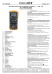
ELCART ART. 09/10000-00 PAGINA 1 DI 6 Manuale di istruzioni/Scheda tecnica MULTIMETRO DIGITALE CON DISPLAY 3 1/2 DIGIT LCD A NORME IEC61010-1 ART. 09/10000-00 NI 10000 MANUALE DI ISTRUZIONI 1. GENERALITÁ: Strumento di misura multifunzione pratico e compatto, resistente ai rischi di rottura dovuti a eventuali cadute. Progettato per seguire le direttive IEC61010-1 e CAT III 600V, sovratensione e doppio isolamento. Per ottenere prestazioni ottimali, la preghiamo di leggere con attenzione questo manuale di istruzioni prima del collegamento, dell’installazione e della messa in funzione di questo prodotto. Conservi il manuale per future consultazioni. Questo strumento di misura è adatto all’uso nelle scuole, nei laboratori o per misurazioni hobbistiche. TAVOLA DEI CONTENUTI: 1. Introduzione 2. Nota di sicurezza 3. Spiegazione dei controlli e degli indicatori 3.1 Illustrazione Prodotto 3.2 Funzionalità dei pulsanti 3.3 Display LCD 6SHFL¿FKH 6SHFL¿FKHJHQHUDOL 6SHFL¿FKHHOHWWULFKH 5. Operazioni di misura 5.1 Misurazione in corrente continua e alternata 5.2 Misurazione di resistenza 5.3 Diodi e controllo di continuità 5.4 Misurazione di capacità 5.5 Prova Transistor 5.6 Misurazione Frequenza 5.7 Misurazioni CC/CA mA / 10A 5.8 Misurazione Induttanza 5.9 Misurazione Temperatura 6. Manutenzione 6.1 Sostituzione Batteria 6.2 Sostituzione Fusibile 6.3 Pulizia 3. SPIEGAZIONE DEI CONTROLLI E DEGLI INDICATORI: 3.1 Illustrazione del prodotto: 1. Display LCD 2. Pulsante "MAX" 3. Pulsante "HOLD" 4. Selettore rotativo 7HUPLQDOLGLLQJUHVVR9ȍ+] 6. Terminale "COM" 7. Terminale "μA mA/Cx Lx hFE" 8. Terminale "10A" 9. Tasto di accensione (ON-OFF) 10. Tasto "FUNC" 11. Tasto "BACKLIGHT" 1 11 10 2 3 9 4 8 5 7 6 3-2 Funzionalità dei pulsanti: PULSANTE FUNZIONE Interruttore di accensione ON / OFF FUNC Utilizzate questo pulsante come selettore per selezionare una funzione tensione CC/CA, corrente CC/CA, resistenza, continuità, temperatura °C/°F HOLD Premendo in sequenza questo pulsante si attiva e disattiva la modalità memoria MAX / MIN Premendo una volta questo pulsante il valore massimo verrà visualizzato (apparirà la scritta MAX sul display) Continuando la misurazione il multimetro aggiornerà continuamente il valore massimo. NOTA: con questa funzione non si intende il valore di picco. BACKLIGHT Questo pulsante è utilizzato per accendere o spegnere la retroilluminazione. Tenendo premuto per più di 2 secondi la luce verrà accesa. Premendo di nuovo, verrà spenta. Ɓ 3.3 Indicatori Display: 2. NOTA DI SICUREZZA: Attenzione Per evitare possibili guasti elettrici o infortuni e per evitare possibili danneggiamenti dello strumento o alle apparecchiature testate, seguite le seguenti regole: - Non applicate una tensione superiore a quella indicata sull’apparecchio tra il terminale di controllo e quello di massa. - Non applicate tensione tra il terminale COM e quello OHM nella misurazione delle resistenze. - Non misurate correnti con i puntali inseriti nei terminali di tensione e OHM - Non esponete l’apparecchio alla luce solare, a temperatura e umidità HOHYDWHRDXQÀXVVRG¶DFTXD - Controllate i puntali per evitare malfunzionamenti. - Prima della misurazione della corrente, controllate il fusibile e spegnete il circuito da misurare prima di iniziare la misurazione. - Scollegate il circuito e scaricate i condensatori prima di misurare la continuità, i diodi, le resistenze, i condensatori e la corrente. SIMBOLI ELETTRICI INTERNAZIONALI: Tensione pericolosa Massa CA (corrente alternata) Attenzione, seguire manuale di istruzioni CC (corrente continua) Doppio isolamento CC oppure CA Fusibile NUMERO INDICATORE SIGNIFICATO 1 Tensione o corrente continua 2 Tensione o corrente alternata 3 Diodo 4 MAX Valore massimo 5 HOLD Data Hold 7 0.ȍ ȍ.ȍ0ȍ8QLWjGLUHVLVWHQ]D 8 °C/°F Unità di temperatura 9 μm VA μV mV V Unità di tensione μA mA A Unità di corrente 10 - Indicatore di letture negative 11 CX Indicatore di capacità 12 LX Indicatore di induttanza 13 mH/H Unità di induttanza 14 nF/μF Unità di capacità 6 Indicatore di batteria scarica ELCART DISTRIBUTION SPA via Michelangelo Buonarroti, 46 - 20093 Cologno Monzese (Milano) ITALY Tel. +39 02.25117310 Fax +39 02.25117610 sito internet: www.elcart.com e-mail: [email protected] La divulgazione dei dati contenuti in questa scheda è da ritenersi un servizio puramente informativo e non costituisce alcun vincolo da parte della Elcart in merito a prestazioni ed utilizzo del prodotto. The divulgation of data contained on this technical sheet are exclusively for informational reasons and establish no link on behalf of Elcart regard to thr performances and the usa of the product. La divulgacion de los datos contenidos en esta ficha son un servicio unicamente informativo y no constituyen ningun vinculo de parte de Elcart respecto a las prestaciones y uso del producto. ELCART ART. 09/10000-00 PAGINA 2 DI 6 Manuale di istruzioni/Scheda tecnica 4. SPECIFICHE 6SHFL¿FKHJHQHUDOL Ɣ'LVSOD\GLJLW/&' YDORUHPDVVLPRYLVXDOL]]DWR Ɣ3URWH]LRQHGDVRYUDFFDULFR XWLOL]]DODSURWH]LRQHGLFLUFXLWR37& per resistenze, condensatori e misurazione di frequenza Ɣ)XQ]LRQH'$7$+2/' Ɣ5HWURLOOXPLQD]LRQH Ɣ$XWRVSHJQLPHQWR Ɣ)XQ]LRQHPHPRUL]]D]LRQHYDORUH0$; Ɣ,QGLFDWRUHEDWWHULDVFDULFDYLVXDOL]]DLOVLPERORGHOODEDWWHULDVXOGLVSOD\ Ɣ7HPSHUDWXUDHXPLGLWjGLODYRUR ·&·)5+ Ɣ7HPSHUDWXUDHXPLGLWjGLFRQVHUYD]·&·)5+ Ɣ$OLPHQWD]LRQH EDWWHULD9WLSR$$[ Ɣ&ODVVHGLVLFXUH]]D ,(&9&$7,,,9&$7,9 Ɣ'LPHQVLRQL/[:[+ [[PP Ɣ3HVR FLUFDJU 4-2 SPECIFICHE ELETTRICHE (a 23±5°C ; <75% RH): 4-2-1 Tensione VCC GAMMA RISOLUZIONE PRECISIONE 200mV 0.1mV GHOODOHWWXUDFLIUH 2V 0.001V GHOODOHWWXUDFLIUH 20V 0.01V GHOODOHWWXUDFLIUH 200V 0.1V GHOODOHWWXUDFLIUH 1000V 1V GHOODOHWWXUDFLIUH ,PSHGHQ]DGLLQJUHVVR -Protezione da sovraccarico: -Tensione Max di ingresso: 0ȍ 250VCC/CA (rms) gamma 200mV 1000VCC 4-2-6 Corrente CC GAMMA RISOLUZIONE PRECISIONE 2mA 1μA GHOODOHWWXUDFLIUH GHOODOHWWXUDFLIUH 20mA 0.01mA 200mA 0.1mA GHOODOHWWXUDFLIUH 10A 0.01A GHOODOHWWXUDFLIUH -Protezione da sovraccarico: -Max corrente di ingresso: fusibile F250mA/1KV per la gamma mA fusibile F10A/1KV per la gamma 10A 200mA ingresso "mA" e 10A ingresso "10A" 4-2-7 Corrente CA GAMMA RISOLUZIONE PRECISIONE 2mA 1μA GHOODOHWWXUDFLIUH 20mA 0.01mA GHOODOHWWXUDFLIUH 200mA 0.1mA GHOODOHWWXUDFLIUH 10A 0.01A GHOODOHWWXUDFLIUH -Protezione da sovraccarico: -Max corrente di ingresso: 5LVSRVWDLQIUHTXHQ]D fusibile F250mA/1KV per la gamma mA fusibile F10A/1KV per la gamma 10A 200mA ingresso "mA" e 10A ingresso "10A" ·+] 4-2-8 Temperatura É possibile selezionare °C oppure °F tramite il tasto "FUNC" GAMMA RISOLUZIONE PRECISIONE ·& 1° ·&GHOODOHWWXUDFLIUH ·&GHOODOHWWXUDFLIUH ·&GHOODOHWWXUDFLIUH ·) 1° ·)GHOODOHWWXUDFLIUH ·)GHOODOHWWXUDFLIUH ·)GHOODOHWWXUDFLIUH 4-2-2 Tensione VCA GAMMA RISOLUZIONE PRECISIONE 200mV 0.1mV GHOODOHWWXUDFLIUH 2V 0.001V GHOODOHWWXUDFLIUH 20V 0.01V GHOODOHWWXUDFLIUH -Protezione da sovraccarico: fusibile F250mA/1KV 200V 0.1V GHOODOHWWXUDFLIUH 4-2-9 Capacità 700V 1V GHOODOHWWXUDFLIUH GAMMA RISOLUZIONE PRECISIONE 2nF 0.001nF GHOODOHWWXUDFLIUH ,PSHGHQ]DGLLQJUHVVR -Protezione da sovraccarico: 5LVSRVWDLQIUHTXHQ]D 5HWWL¿FDWRUHPHGLR -Tensione Max di ingresso: 0ȍ 250VCC/CA (rms) gamma 200mV ·+] 750VCA rms 4-2-3 Resistenza GAMMA RISOLUZIONE PRECISIONE ȍ ȍ GHOODOHWWXUDFLIUH .ȍ .ȍ GHOODOHWWXUDFLIUH .ȍ .ȍ GHOODOHWWXUDFLIUH .ȍ .ȍ GHOODOHWWXUDFLIUH 0ȍ 0ȍ GHOODOHWWXUDFLIUH 0ȍ 0ȍ GHOODOHWWXUDFLIUH -Protezione da sovraccarico: 250VCC/CA rms 4-2-4 Diodi GAMMA RISOLUZIONE FUNZIONE 0.001V visualizza la tensione di caduta del diodo -Protezione da sovraccarico: 250VCC/CA rms 4-2-5 Continuità 20nF 0.01nF GHOODOHWWXUDFLIUH 200nF 0.1nF GHOODOHWWXUDFLIUH GHOODOHWWXUDFLIUH 2μF 0.001μF 20μF 0.01μF GHOODOHWWXUDFLIUH 200μ 0.1μF GHOODOHWWXUDFLIUH -Protezione da sovraccarico: fusibile F250mA/1KV K)( GAMMA FUNZIONE hFE K)(· -Protezione da sovraccarico: fusibile F250mA/1KV 4-2-11 Frequenza GAMMA RISOLUZIONE PRECISIONE 20KHz 1Hz GHOODOHWWXUDFLIUH -Sensibilità: -Protezione da sovraccarico: 200mV - 5VCA rms 250VCC/CA rms 4-2-12 Induttanza GAMMA RISOLUZIONE PRECISIONE 2mH 0.001mH GHOODOHWWXUDFLIUH 20mH 0.01mH GHOODOHWWXUDFLIUH FUNZIONE 200mH 0.1mH GHOODOHWWXUDFLIUH VHODUHVLVWHQ]DPLVXUDWDqLQIHULRUHDLȍLOEX]]HUVXRQD 2H 1mH GHOODOHWWXUDFLIUH 20H 10mH GHOODOHWWXUDFLIUH GAMMA -Protezione da sovraccarico: 250VCC/CA rms -Protezione da sovraccarico: fusibile F250mA/1KV ELCART DISTRIBUTION SPA via Michelangelo Buonarroti, 46 - 20093 Cologno Monzese (Milano) ITALY Tel. +39 02.25117310 Fax +39 02.25117610 sito internet: www.elcart.com e-mail: [email protected] La divulgazione dei dati contenuti in questa scheda è da ritenersi un servizio puramente informativo e non costituisce alcun vincolo da parte della Elcart in merito a prestazioni ed utilizzo del prodotto. The divulgation of data contained on this technical sheet are exclusively for informational reasons and establish no link on behalf of Elcart regard to thr performances and the usa of the product. La divulgacion de los datos contenidos en esta ficha son un servicio unicamente informativo y no constituyen ningun vinculo de parte de Elcart respecto a las prestaciones y uso del producto. ART. 09/10000-00 ELCART Manuale di istruzioni/Scheda tecnica 5. OPERAZIONI DI MISURA: 5-1 Misurazione di tensione VCC e VCA Per evitare possibili guasti elettrici o infortuni dovuti a un non corretto utilizzo dello strumento, non tentate di misurare tensioni più alte di 1000VCC/700VCA Gamme di misurazione della tensione CC: 200mV, 2V, 20V, 200V e 1000V Gamme di misurazione della tensione CA: 2V, 20V, 200V e 750V Per misurazioni in tensione CC e CA collegate lo strumento come segue: ,QVHULWHLOSXQWDOHURVVRQHOWHUPLQDOH9ȍHLOQHURQHOWHUPLQDOH&20 2. Lo strumento ha come funzione di default la misurazione CC, potete selezionare la funzione CA con il tasto ‘FUNC" 5XRWDWHODPDQRSRODVXOODJDPPDGLPLVXUD]LRQH&&&$P9R9 4. Collegate i puntali all’apparecchiatura da misurare; Il valore misurato verrà visualizzato sul display 5. Il display LCD visualizzerà "OL" nel caso di circuito aperto o nel caso in cui il valore misurato sia superiore alla gamma utilizzata 5-2 Misurazione di Resistenza Per evitare possibili guasti, scollegate ogni alimentazione DOO¶DSSDUHFFKLDWXUDGDPLVXUDUHHVFDULFDWHWXWWLL condensatori prima di effettuare misurazioni di resistenza *DPPHGLPLVXUD]LRQH ȍ.ȍ.ȍ.ȍ0ȍ0ȍ Per misurare la resistenza collegate lo strumento come segue: ,QVHULWHLOSXQWDOHURVVRQHOWHUPLQDOH9ȍHLOQHURQHOWHUPLQDOH&20 5XRWDWHODPDQRSRODVXOODJDPPDGLPLVXUD]LRQHGHVLGHUDWD 3. Collegate i puntali all’apparecchiatura da misurare. Il valore misurato verrà visualizzato sul display Note: ,SXQWDOLSRVVRQRDJJLXQJHUHDOODPLVXUDGLUHVLVWHQ]DȍGLHUURUH per la resistenza interna degli stessi. Per ottenere una lettura precisa per valori bassi di resistenza, cortocircuitate i puntali con la manopola sulla JDPPDȍLQTXHVWRPRGRYLVXDOL]]HUHWHODUHVLVWHQ]DLQWHUQDGHL puntali. Sottraendola alla misurazione sul circuito avrete il valore preciso. 3HUPLVXUD]LRQLGLDOWHUHVLVWHQ]H!0ȍYLFRQVLJOLDPRGLHIIHWWXDUH due misure e di confrontare i due risultati. - Il display LCD visualizzerà "OL" nel caso di circuito aperto o nel caso in cui il valore misurato sia superiore alla gamma utilizzata. 5-3 Diodi / Test di Continuità Per evitare possibili guasti, scollegate ogni alimentazione DOO¶DSSDUHFFKLDWXUDGDPLVXUDUHHVFDULFDWHWXWWLLFRQGHQVDWRUL prima di effettuare misurazioni di diodi o test di continuità ,QVHULWHLOSXQWDOHURVVRQHOWHUPLQDOH9ȍHLOQHURQHOWHUPLQDOH&20 5XRWDWHODPDQRSRODVXOODSRVL]LRQH 3. Per una corretta misurazione della tensione di caduta di tutti i semiconduttori, ponete il terminale rosso sull’anodo del componente e quello nero sul catodo. Il valore verrà visualizzato sul display Test di continuità: Premete il tasto "FUNC" per entrare nella funzionalità di continuità. ,OEX]]HUVXRQDVHODUHVLVWHQ]DGHOFLUFXLWRWHVWDWRpLQIHULRUHDLȍ 5-4 Misurazione di Capacità Per evitare possibili guasti, scollegate ogni alimentazione DOO¶DSSDUHFFKLDWXUDGDPLVXUDUHHVFDULFDWHWXWWLL condensatori prima di effettuare misurazioni di capacità Gamme di misurazione: 2nF, 20nF, 200nF, 2μF, 20μF, 200μF Per misurare la capacità, collegate il multimetro come segue: 5XRWDWHODPDQRSRODQHOOD]RQDGHOOHJDPPH)SUHVWDQGRDWWHQ]LRQH al valore del condensatore da misurare. 2. Per una misura corretta utilizzate la presa doppia in dotazione. I due terminali "Cx/Lx/Temp" e "COM" della presa doppia devono essere collegati rispettivamente ai terminali " " e "COM" del multimetro. Inserite il condensatore da misurare nei due fori della presa. Il valore misurato verrà visualizzato sul display. Note: - Per misurare correttamente alte capacità, vi suggeriamo di ripetere più volte la misura e poi fare la media tra i risultati ottenuti. - Per aumentare la precisione della misurazione di condensatori di valore inferiore ai 5nF, collegate un condensatore da 0.15μF in parallelo. 5-5 Prova Transistor Per evitare malfunzionamenti o guasti, la tensione tra i terminali &20HK)(GHYHHVVHUHLQIHULRUHD9&&9&$ 5XRWDWHODPDQRSRODVXOODJDPPDGLPLVXUD]LRQHK)( 2. Collegate la presa doppia in dotazione ai terminali "hFE" e "COM". 3. I transistor (contenitore TO92) a 3 pin devono essere correttamente inseriti ai terminali ‘e’,’b’,’c’. Il valore misurato verrà visualizzato sul display. PAGINA 3 DI 6 5-6 Misurazione Frequenza Per evitare malfunzionamenti o guasti, la tensione tra i terminali &20HK)(GHYHHVVHUHLQIHULRUHD9&&9&$ 5XRWDWHODPDQRSRODVXOODJDPPDGLPLVXUD]LRQH.+] 2. Inserite il puntale rosso nel terminale "Hz" e il nero nel terminale "COM" 3. Collegate i puntali al circuito da misurare; leggete il valore sul display. Note: Il livello del segnale di ingresso deve essere superiore a 0.2V. 5-7 Misurazioni CC/CA mA/10A Se la tensione di alimentazione tra il circuito aperto e la massa è >250V, non tentate di misurare la corrente; se la misurazione dovesse far saltare il fusibile, si potrebbero creare guasti allo strumento e problemi all’utilizzatore. Per evitare guasti al multimetro o al circuito da misurare, controllate bene il fusibile prima di procedure alla misurazione. Seguite bene la procedura indicata in questo manuale per evitare malfunzionamenti o problemi. Gamme di misurazione CC/CA: 2mA, 20mA, 200mA, 10A 1. Togliete l’alimentazione al circuito da misurare e scaricate tutti i condensatori 5XRWDWHODPDQRSRODVXOODJDPPDGLPLVXUD]LRQH&&&$P$GHVLGHUDWD 2. Collegate il multimetro in serie al circuito. 3. Date alimentazione al circuito da misurare; leggete il valore sul display. 4. Se verrà visualizzato il simbolo "OL", dovrete ruotare la manopola su una gamma di misurazione maggiore. 5. Se la corrente del circuito è compresa tra 200mA e 10A , inserite il puntale rosso nel terminale "10A". 6. Seguite il punto precedente per procedere alla misurazione. Note: ,OWHPSRGLPLVXUDSHUDOWHFRUUHQWLGHYHHVVHUHVHFRQGLHO¶LQWHUYDOOR tra una misurazione e l’altra deve essere almeno di 5 minuti. Al termine della misurazione,scollegate i puntali dall’apparecchiatura testata 5-8 Misurazione Induttanza Gamme di misurazione dell’induttanza: 2mH, 20mH, 200mH, 2H, 20H Per misurare l’induttanza, collegate il multimetro come segue: 1. Inserite il puntale rosso nel terminale "Lx" e il nero nel terminale COM. 5XRWDWHODPDQRSRODVXOODJDPPDGLPLVXUD]LRQHGHOO¶LQGXWWDQ]D 3. Collegate i puntali al circuito da misurare; leggete il valore sul display. 5-9 Misurazione Temperatura 1. Selezionate con la manopola la funzione "TEMP". Sul display verrà visualizzata la scritta "OL". 2. Collegate la presa doppia in dotazione ai due terminali "COM" e "TEMP" del multimetro. 3. Inserite la termocoppia nei due fori della presa doppia. Prendete nota di questa polarità. 4. La misurazione della temperatura verrà visualizzata sul display. 6. Manutenzione 6-1 Sostituzione della batteria Quando sul display verrà visualizzato il simbolo della batteria, sarà necessario sostituirla. 1. Scollegate e rimuovete tutti i puntali. 2. Aprite lo sportello della batteria con un cacciavite. 3. Sostituite la vecchia batteria con una nuova; richiudete il coperchio 6-2 Sostituzione fusibile Sostituite il fusibile guasto seguendo le seguenti indicazioni: 1. Per evitare rischi, rimuovete i puntali e qualsiasi segnale di ingresso prima di aprire il coperchio sottostante. 2. Aprite il coperchio, rimuovete il fusibile guasto e inserite quello nuovo con le stesse caratteristiche e dimensioni. 5LFKLXGHWHLOFRSHUFKLRFRQXQFDFFLDYLWH 6-3 Pulizia Utilizzare un panno asciutto senza oli o altre sostanze detergenti. Informazione agli utenti ex art. 26 D.Lgs. 49/2014 Il simbolo riportato sull’apparecchiatura (Allegato IX D.Lgs. 49/2014) LQGLFDFKHLOULÀXWRGHYHHVVHUHRJJHWWRGL´UDFFROWDVHSDUDWDµHFKHqVWDWR immesso sul mercato, in Italia, dopo il 31/12/2010. Pertanto, l’utente GRYUjFRQIHULUHRIDUFRQIHULUHLOULÀXWRDLFHQWULGLUDFFROWDGLͿHUHQ]LDWD SUHGLVSRVWLGDOOHDPPLQLVWUD]LRQLORFDOLRSSXUHFRQVHJQDUORDOULYHQGLWRUH FRQWURDFTXLVWRGLXQDQXRYDDSSDUHFFKLDWXUDGLWLSRHTXLYDOHQWH /·XWHQWHKDGXQTXHXQUXRORDWWLYRODUDFFROWDGLͿHUHQ]LDWDGHOULÀXWRHOH VXFFHVVLYHRSHUD]LRQLGLWUDWWDPHQWRUHFXSHURHVPDOWLPHQWRIDYRULVFRQR OD SURGX]LRQH GL DSSDUHFFKLDWXUH FRQ PDWHULDOL ULFLFODWL H OLPLWDQR JOL HͿHWWL QHJDWLYL VXOO·DPELHQWH H VXOOD VDOXWH HYHQWXDOPHQWH FDXVDWL GD XQD JHVWLRQHLPSURSULDGHOULÀXWR1HOFDVRGL5$((GLSLFFROLVVLPHGLPHQVLRQL FP O·XWHQWH KD GLULWWR DO FRQIHULPHQWR JUDWXLWR VHQ]D REEOLJR GL FRQWHVWXDOHDFTXLVWRDLGLVWULEXWRULDOGHWWDJOLRODFXLVXSHUÀFLHGLYHQGLWD VSHFLDOL]]DWDHFFHGHLPT IMPORTATO E DISTRIBUITO DA ELCART DISTRIBUTION SPA Via Michelangelo Buonarroti, 46 20093 COLOGNO MONZESE (MI) ITALY www.elcart.com - [email protected] Made in China ELCART DISTRIBUTION SPA via Michelangelo Buonarroti, 46 - 20093 Cologno Monzese (Milano) ITALY Tel. +39 02.25117310 Fax +39 02.25117610 sito internet: www.elcart.com e-mail: [email protected] La divulgazione dei dati contenuti in questa scheda è da ritenersi un servizio puramente informativo e non costituisce alcun vincolo da parte della Elcart in merito a prestazioni ed utilizzo del prodotto. The divulgation of data contained on this technical sheet are exclusively for informational reasons and establish no link on behalf of Elcart regard to thr performances and the usa of the product. La divulgacion de los datos contenidos en esta ficha son un servicio unicamente informativo y no constituyen ningun vinculo de parte de Elcart respecto a las prestaciones y uso del producto. ELCART ART. 09/10000-00 PAGINA 4 DI 6 Manuale di istruzioni/Scheda tecnica DIGITAL MULTIMETER WITH DISPLAY 3 1/2 DIGIT LCD ACCORDING TO IEC61010-1 ART. 09/10000-00 NI 10000 USER'S MANUAL 1. INTRODUCTION: This Meter is a handheld and battery operated Digital Multi Meter (DMM) with multi function. This Meter is designed to meet IEC-61010-1 CAT III 1000V over voltage category and double insulation. The entire outer surface of the case has been formed with thermo plastic elastomer, giving the main body, though downsized, high resistance against the shock of a drop. This operating instruction covers information on safety and caution. Please read relevant information carefully and observe all the warnings and note strictly. The DMM as general measurement tool and widely used in the VFKRROODERUDWRU\IDFWRU\HWFVRFLDO¿HOG TABLE OF CONTENTS: 1. Introduction 2. Safety note 3. Explanation of controls and indicators 3.1 Meter illustration 3.2 Functional push button 3.3 Display indicators 6SHFL¿FDWLRQ 4.1 General Feature (OHFWULFDO6SHFL¿FDWLRQD&5+ 5. Measurement operation 5-1 DC & AC voltage measurement 5HVLVWDQFHPHDVXUHPHQW 5-3 Diode/Continuity check 5-4 Capacitance measurement 5-5 Transistor check 5-6 Frequency measurement 5-7 DC/AC mA/10A measurement 5-8 Inductance measurement 5-9 Temperature measurement 6. Maintenance 5HSODFLQJWKHEDWWHU\ 6-2. Fuse replacement 6-3 Cleaning and Decontamination 3. EXPLANATION OF CONTROLS AND INDICATORS 3.1 Meter illustration: 1. LCD Display 2. "MAX" push button 3. "HOLD" push button 5RWDU\6ZLWFK.QRE 9ȍ+]LQSXWWHUPLQDO 6. "COM" input terminal 7. "μA mA/Cx Lx hFE" input terminal 8. "10A" input terminal 9. Power switch (ON-OFF) 10. "FUNC" push button 11. "BACKLIGHT" push button 1 11 10 2 3 9 4 8 5 7 6 )XQFWLRQDOSXVKEXWWRQ PUSH BUTTON FUNCTION Power switch ON / OFF FUNC "FUNC" key is the function select key that acts with trigger. Use the key as switch of AC/DC voltage, AC/DC current, resistance/continuity and °C/°F. HOLD Press "HOLD" to enter and exit the hold mode in any mode. That act with trigger. MAX / MIN This key is act with trigger. Press this key once, the max value is holding (will displays ‘MAX’ symbol in the LCD). After pressing the key, A/D will keep working, and the display value are always up dated and kept the max value. (The actual gained value is not the peak value.). BACKLIGHT Ɓ This key is used to control backlight. This key is act with trigger. :KHQSUHVVWKHNH\ZLOOHQDEOHEDFNOLJKWIRUVHF Press the key again within 15 sec, backlight will disable. 3.3 Display indicators: 2. SAFETY NOTE: Warning To avoid possible electric shock or personal injury and to avoid possible damage to the meter or to the equipment under test, adhere to the following rule: - Do not apply more than the rated voltage of marked on the meter - Do not apply voltage between COM and OHM terminal, in the resistance measuring state. - Do not measure current with test lead inserted into voltage or OHM terminal. - Do not expose the instrument to the direct sun light, extreme temperature and humidity or dew full. - Inspect the test lead for damaged insulation or exposed metal. - Before measuring current, check the Meter’s fuses and turn off power to the circuit before connecting the meter to the circuit. - Disconnect circuit power and discharge all high voltage capacitors before testing continuity, diode, resistance, capacitance or current. NOTE INTERNATIONAL ELECTRICAL SYMBOL. Dangerous Voltage Ground AC (Alternating current) :DUQLQJVHHH[SODLQ in manual DC (Direct current) Double insulation AC or DC Fuse NUMBER INDICATOR MEANING 1 DC voltage or current 2 AC voltage or current 3 Diode 4 MAX 5 HOLD 6 Maximum value Data hold Low battery indicator 7 0.ȍ ȍ.ȍ0ȍLVXQLWRIUHVLVWDQFH 8 °C/°F The unit of temperature 9 μm VA uV mV V is unit of voltage uA mA A is unit of current 10 - Indicate negative reading 11 CX Capacitance Indicator 12 LX Inductance Indicator 13 mH/H Inductance Units 14 nF/μF Capacitance Units ELCART DISTRIBUTION SPA via Michelangelo Buonarroti, 46 - 20093 Cologno Monzese (Milano) ITALY Tel. +39 02.25117310 Fax +39 02.25117610 sito internet: www.elcart.com e-mail: [email protected] La divulgazione dei dati contenuti in questa scheda è da ritenersi un servizio puramente informativo e non costituisce alcun vincolo da parte della Elcart in merito a prestazioni ed utilizzo del prodotto. The divulgation of data contained on this technical sheet are exclusively for informational reasons and establish no link on behalf of Elcart regard to thr performances and the usa of the product. La divulgacion de los datos contenidos en esta ficha son un servicio unicamente informativo y no constituyen ningun vinculo de parte de Elcart respecto a las prestaciones y uso del producto. ELCART ART. 09/10000-00 4. SPECIFICATION 4-1 General Feature: Ɣ'LVSOD\GLJLW/&' PD[YDOXHGLVSOD\HG Ɣ2YHUORDGSURWHFWLRQ 8VHGWKH37&SURWHFWLRQFLUFXLWIRUUHVLVWDQFH capacitance and frequency measurement Ɣ'$7$+2/'IXQFWLRQ Ɣ%DFN/LJKW Ɣ$XWR3RZHU2)) Ɣ0$;YDOXHPHDVXUHPHQWIXQFWLRQ Ɣ/RZEDWWHU\LQGLFDWLRQ EDWWHU\VLPERORQWKHGLVSOD\ Ɣ2SHUDWLQJWHPSHUDWXUH+XPLGLW\ ·&·)DQG5+ Ɣ6WRUDJHWHPSHUDWXUH+XPLGLW\ ·&·)DQG5+ Ɣ3RZHU6XSSO\ 9EDWWHU\$$7\SH[ Ɣ6DIHW\&ODVV ,(&9&$7,,,9&$7,9 Ɣ'LPHQVLRQV/[:[+ [[PP Ɣ:HLJKW DSSUR[JU 4-2 ELECTRICAL SPECIFICATION (AT 23±5°C; <75% RH) 4-2-1 DC Voltage RANGE RESOLUTION ACCURACY 200mV 0.1mV RIUGJGJW 2V 0.001V RIUGJGJW 20V 0.01V RIUGJGJW 200V 0.1V RIUGJGJW 1000V 1V RIUGJGJW ,QSXWLPSHGDQFH - Over load protection: - Max input voltage: 4-2-2 AC Voltage 0ȍ 250V AC/DC (rms) at 200mV range 1000VDC RANGE RESOLUTION ACCURACY 200mV 0.1mV RIUGJGJW 2V 0.001V RIUGJGJW 20V 0.01V RIUGJGJW 200V 0.1V RIUGJGJW 700V 1V RIUGJGJW ,QSXWLPSHGDQFH -Over load protection: )UHTXHQF\UHVSRQVH $YHUDJHUHFWL¿HUW\SH -Max input voltage: 0ȍ 250V AC/DC (rms) at 200mV range ·+] 750VAC rms 4-2-3 Resistance RANGE RESOLUTION ACCURACY ȍ ȍ RIUGJGJW .ȍ .ȍ RIUGJGJW .ȍ .ȍ RIUGJGJW .ȍ .ȍ RIUGJGJW 0ȍ 0ȍ RIUGJGJW 0ȍ 0ȍ RIUGJGJW -Over load protection: 250V AC/DC rms 'LRGHFKHFN RANGE RESOLUTION FUNCTION 0.001V :LOOGLVSOD\WKHIRUZDUGGURSYROWDJH -Over load protection: 250V AC/DC rms 4-2-5 Continuity test RANGE FUNCTION ,IPHDVXUHGUHVLVWDQFHOHVVWKDQȍZLOOEX]]HULVVRXQGHG -Over load protection: PAGINA 5 DI 6 Manuale di istruzioni/Scheda tecnica 250V AC/DC rms 4-2-6 DC current RANGE RESOLUTION ACCURACY 2mA 1μA RIUGJGJW 20mA 0.01mA RIUGJGJW 200mA 0.1mA RIUGJGJW 10A 0.01A RIUGJGJW -Over load protection: fuse (F250mA/1KV) at mA range fuse (F10A/1KV) at 10A range 200mA at ‘mA’ jack and 10A at ‘10A’ jack -Max input current: 4-2-7 AC current RANGE RESOLUTION ACCURACY 2mA 1μA RIUGJGJW 20mA 0.01mA RIUGJGJW 200mA 0.1mA RIUGJGJW 10A 0.01A RIUGJGJW -Over load protection: fuse (F250mA/1KV) at mA range fuse (F10A/1KV) at 10A range 200mA at ‘mA’ jack and 10A at ‘10A’ jack ·+] -Max input current: )UHTXHQF\UHVSRQVH 4-2-8 Temperature You can selecting Centi-degree (°C) or Fahrenheit (°F) by "FUNC" key. RANGE RESOLUTION ACCURACY ·& 1° ·&RIUGJGJW ·&RIUGJGJW ·&RIUGJGJW ·) 1° ·)RIUGJGJW ·)RIUGJGJW ·)RIUGJGJW -Over load protection: fuse F250mA/1KV 4-2-9 Capacitance RANGE RESOLUTION ACCURACY 2nF 0.001nF RIUGJGJW 20nF 0.01nF RIUGJGJW 200nF 0.1nF RIUGJGJW 2μF 0.001μF RIUGJGJW 20μF 0.01μF RIUGJGJW 200μ 0.1μF RIUGJGJW -Over load protection: fuse F250mA/1KV K)( RANGE FUNCTION hFE K)(· -Over load protection: 4-2-11 Frequency fuse F250mA/1KV RANGE RESOLUTION ACCURACY 20KHz 1Hz RIUGJGJW -Sensitivity: -Over load protection: 200mV -5V AC rms 250VAC/DC rms 4-2-12 Inductance RANGE RESOLUTION ACCURACY 2mH 0.001mH RIUGJGJW 20mH 0.01mH RIUGJGJW 200mH 0.1mH RIUGJGJW 2H 1mH RIUGJGJW 20H 10mH RIUGJGJW -Over load protection: fuse F250mA/1KV ELCART DISTRIBUTION SPA via Michelangelo Buonarroti, 46 - 20093 Cologno Monzese (Milano) ITALY Tel. +39 02.25117310 Fax +39 02.25117610 sito internet: www.elcart.com e-mail: [email protected] La divulgazione dei dati contenuti in questa scheda è da ritenersi un servizio puramente informativo e non costituisce alcun vincolo da parte della Elcart in merito a prestazioni ed utilizzo del prodotto. The divulgation of data contained on this technical sheet are exclusively for informational reasons and establish no link on behalf of Elcart regard to thr performances and the usa of the product. La divulgacion de los datos contenidos en esta ficha son un servicio unicamente informativo y no constituyen ningun vinculo de parte de Elcart respecto a las prestaciones y uso del producto. ART. 09/10000-00 ELCART Manuale di istruzioni/Scheda tecnica 5. MEASUREMENT OPERATION: 5-1 AC/DC voltage measurement 7RDYRLGKDUPVWR\RXRUGDPDJHWRWKHPHWHUIURPHOHFWULF VKRFN3OHDVHGRQRWDWWHPSWWRPHDVXUHYROWDJHKLJKHUWKDQ '&9$&9UPVDOWKRXJKUHDGLQJVPD\EHREWDLQHG AC voltage ranges are: 200mV, 2V, 20V, 200V and 750V DC voltage ranges are: 200mV, 2V, 20V, 200V and 1000V ,QVHUWWKHUHGWHVWOHDGLQWRWKH9ȍLQSXWWHUPLQDODQGWKHEODFNWHVW lead into the COM input terminal. 2. First time, default mode is DC measurement mode, you can select the AC voltage mode by "FUNC" key. 3. Set the rotary switch to proper AC/DC mV or V range. 4. Connect the test lead across with the object being measured. 5HDGWKHYDOXHGLVSOD\HGRQWKH/&' 5. If the "OL" symbol is displayed on the display, you must be set the rotary switch to the higher range. 5-2 Resistance measurement 7RDYRLGGDPDJHWRWKHPHWHURUWRWKHHTXLSPHQWXQGHU WHVWGLVFRQQHFWSRZHUDQGGLVFKDUJHDOOKLJKYROWDJH capacitors before resistance measurement. 7KHUHVLVWDQFHUDQJHDUH ȍ.ȍ.ȍ.ȍ0ȍ0ȍ ,QVHUWWKHUHGWHVWOHDGLQWRWKH9ȍWHUPLQDODQGWKHEODFNWHVWOHDG into the COM terminal. 2. Set the rotary switch to proper resistance range. 3. Connect the test lead across with the object being measured. 5HDGWKHYDOXHGLVSOD\HGRQWKH/&' Note: 7KHWHVWOHDGFDQDGGȍWRȍRIHUURUWRUHVLVWDQFHPHDVXUHPHQW To obtain precision reading in low-resistance measurement, that is the UDQJHRIȍVKRUWWKHLQSXWWHUPLQDOEHIRUHPHDVXULQJ In this time, the contact resistance is displayed on the LCD. You can subtract the contact resistance value from the measured value. )RUKLJKUHVLVWDQFHPHDVXUHPHQW!0ȍLWLVQRUPDOWDNLQJVHYHUDO second to obtain stable reading. - The LCD display "OL" indicating open-circuit for the tested resistor or the resistor value is higher than the maximum range of the meter. 'LRGH&RQWLQXLW\FKHFN 7RDYRLGGDPDJHWRWKHPHWHURUWRWKHHTXLSPHQWXQGHUWHVW GLVFRQQHFWSRZHUDQGGLVFKDUJHDOOKLJKYROWDJHFDSDFLWRUV EHIRUH'LRGH&RQWLQXLW\FKHFN ,QVHUWWKHUHGWHVWOHDGLQWRWKH9ȍWHUPLQDODQGWKHEODFNWHVWOHDG into the COM terminal. 2. Set the rotary switch to position. 3. For forward voltage drop reading on any semiconductor component, place the red test lead on the component anode and place the black test lead RQWKHFRPSRQHQWFDWKRGH5HDGWKHYDOXHGLVSOD\HGRQWKH/&' 4. Select the continuity check mode by the "FUNC" key. 7KHEX]]HUPD\EHVRXQGLIWKHUHVLVWDQFHRIDFLUFXLWXQGHUWHVWLVȍ 5-4 Capacitance measurement 7RDYRLGGDPDJHWRWKHPHWHURUWRWKHHTXLSPHQWXQGHU WHVWGLVFRQQHFWSRZHUDQGGLVFKDUJHDOOKLJKYROWDJH capacitors before measuring capacitance. Capacitance ranges are: 2nF, 20nF, 200nF, 2μF, 20μF, 200μF 1. Set the rotary switch to "F" proper position, according to about capacitance value of capacitor under measured. 2. For the convenience of user, provided the multi function socket as accessory First time, insert the socket to the " " input terminal and "COM" terminal, and then insert the capacitor to the two holes on the socket. The pin marked "Cx/Lx/Temp" is pointed to the " " input terminal, and the pin marked "COM" is pointed "COM" input terminal respectively. 5HDGWKHYDOXHGLVSOD\HGRQWKH/&' Note: To measuring large capacitance, stabilize the reading will take some time. To increase the accuracy of capacitance measurement when measuring under 5nF capacitance, you can connecting 0.15μF capacitor in parallel with the capacitor being measured. 7UDQVLVWRUFKHFN 'RQRWDWWHPSWDSSO\$&'&YROWDJHPRUHWKDQ9EHWZHHQ&20 DQGK)(WHUPLQDOWRDYRLGGDPDJHWRWKHPHWHUIURPHOHFWULFVKRFN 1. Set the rotary switch to the hFE position. 2. Use the special multi-function socket, and then it’s hFE pin must be inserted to the hFE input terminal, and COM pin should be inserted to the COM terminal. 3. Transistor (TO92 package type) 3 pins must be correctly inserted to the "e", "b", "c" insert hole of the multi-function socket respectively according to the NPN or PNP type. The hFE value will displayed on the LCD. PAGINA 6 DI 6 5-6 Frequency measurement 7RDYRLGGDPDJHWKHPHWHURUHOHFWULFVKRFNWKHYROWDJHPXVW OHVVWKDQ9'&RU$&UPVEHWZHHQ&20DQGK)( 1. Set the rotary switch to "20KHz" position. 2. Insert the red test lead into the "Hz" input terminal and the black test lead into the "COM" terminal. 3. Connect the test leads across with the circuit under testing. The measured value show on the LCD display. Note: Input signal level must be higher than 0.2V (it is sensitivity). 5-7 AC/DC mA/10A measurement :KHQWKHYROWDJHPRUHWKDQ9EHWZHHQRSHQFLUFXLWDQG JURXQGGRQRWWRWU\WRPHDVXUHWKHFXUUHQW ,IWKHPHDVXUHPHQWVZHUHEORZQIXVHWKLVPD\GDPDJHWKH instrument or injury to yourself. In order to avoid damage instrumentation or test equipment, before measurement curUHQWSOHDVHFKHFNWKHLQVWUXPHQWIXVH7KHLQSXWVRFNHWWKH IXQFWLRQDOSUR¿OHDQGUDQJHVKRXOGEHXVHFRUUHFWO\ZKHQPHDVXUHFXUUHQW:KHQWKHWHVWOHDGHUZDVLQVHUWHGDWWKHFXUUHQW LQSXWVRFNHWGRQRWDWWHPSWWRWKHRWKHUVLGHRIWKHWHVWOHDGHU connect any circuit. AC/DC Current range are: 2mA, 20mA, 200mA, 10A 1. Turn off power to the circuit and discharge all high-voltage capacitors Set the rotary switch to the proper AC/DC mA position. 2. Break the current path to be tested. Connect the red test lead to the more positive side of the break and the black test lead to the more negative side of the break. 3. Turn on power to the circuit, the measured value show on the LCD. 4. If the "OL" symbol displayed on the LCD, you must be set the rotary switch to the higher range. :KHQWKHFXUUHQWLVEHWZHHQP$DQG$LQVHUWWKHUHGWHVWOHDG into the input terminal marked as "10A". 6. The measuring procedure is same as that of 1-4 section. Note: For safety sake, the measuring time for high current should be less than 10 second for each measurement and the interval time between two measurement should be greater than 5 minutes. :KHQFXUUHQWPHDVXUHPHQWKDVEHHQFRPSOHWHGGLVFRQQHFWWKHFRQQHFWLRQ between the testing lead and the circuit under test. 5-8 Inductance measurement Inductance range are: 2mH, 20mH, 200mH, 2H, 20H 1. Insert the red test lead into the "Lx" terminal and the black test lead into the COM terminal. 2. Set the rotary switch to proper inductance range. 3. Connect the test lead across with the inductor being measured. The inductance value will be displayed on the LCD. 5-9 Temperature measurement 1. Set the rotary switch to the "TEMP" range; "OL" displayed on the LCD. 2. Insert the Socket to the two "COM" and "TEMP" terminals. 3. Insert the K-type temperature probe to the two insert holes of socket. User should be take note of it’s polarity. 4. The measured temperature value will be displayed on the LCD. 6 Maintenance 5HSODFLQJWKHEDWWHU\ :KHQPHWHUGLVSOD\WKHEDWWHU\PXVWEHUHSODFHWRPDLQWDLQQRUPDORSHUDWLRQ 1. Disconnect and remove all test probes from any live source and meter 2. Open the battery cover on the bottom case by screwdriver 5HPRYHROGEDWWHU\DQGVQDSQHZRQHLQWREDWWHU\KROGHU 6-2 Fuse replacement 5HSODFLQJWKHGHIHFWLYHIXVHDFFRUGLQJWRWKHIROORZLQJSURFHGXUH 5HPRYHWKHWHVWOHDGDQGWXUQRIISRZHU 2. Open the battery cover on the bottom 5HPRYHWKHGHIHFWLYHIXVHDQGLQVHUWDQHZIXVHRIWKHVDPHVL]HDQGUDWLQJ 5HSODFHWKHERWWRPFDVHDQGUHLQVWDOODOOWKHVFUHZ 6-3 Cleaning and Decontamination Can be cleaned with soft clean cloth to remove any oil, grease or grim. Do not use liquid solvent. User information ex art. 26 D. 49/2014 The symbol labelled on the appliance (Annex IX D. 49/2014) indicates that WKH UXEELVK LV VXEMHFW WR ´VHSDUDWH FROOHFWLRQµ DQG LW KDV EHHQ SODFHG RQ the Italian market after the December 31, 2010. The user must therefore DVVLJQ RU KDYH FROOHFWHG WKH UXEELVK WR D WUHDWPHQW IDFLOLW\ DFFRUGLQJ WR LQGLFDWLRQV E\ WKH ORFDO DGPLQLVWUDWLRQ RU KDQG LW RYHU WR WKH UHVHOOHU LQ H[FKDQJH IRU DQ HTXLYDOHQW QHZ SURGXFW 7KH VHSDUDWH FROOHFWLRQ RI WKH rubbish and the subsequent treatment, recycling and disposal operations encourage the production of appliances made with recycled materials and UHGXFHQHJDWLYHHͿHFWVRQKHDOWKDQGWKHHQYLURQPHQWFDXVHGE\LPSURSHU WUHDWPHQWRIUXEELVK,QWKHFDVHRIYHU\VPDOO:(((QRH[WHUQDOGLPHQVLRQ more than 25 cm), the user is eligible to get free of charge assignation to retail shops with sales areas relating to EEE of at least 400 m². ,03257('$1'',675,%87('%< ELCART DISTRIBUTION SPA Via Michelangelo Buonarroti, 46 20093 COLOGNO MONZESE (MI) - ITALY www.elcart.com - [email protected] Made in China ELCART DISTRIBUTION SPA via Michelangelo Buonarroti, 46 - 20093 Cologno Monzese (Milano) ITALY Tel. +39 02.25117310 Fax +39 02.25117610 sito internet: www.elcart.com e-mail: [email protected] La divulgazione dei dati contenuti in questa scheda è da ritenersi un servizio puramente informativo e non costituisce alcun vincolo da parte della Elcart in merito a prestazioni ed utilizzo del prodotto. The divulgation of data contained on this technical sheet are exclusively for informational reasons and establish no link on behalf of Elcart regard to thr performances and the usa of the product. La divulgacion de los datos contenidos en esta ficha son un servicio unicamente informativo y no constituyen ningun vinculo de parte de Elcart respecto a las prestaciones y uso del producto.