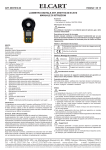
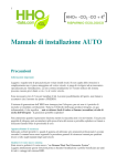
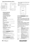
1
ART. 09/09600-00 ELCART Manuale di istruzioni/Scheda tecnica PAGINA 1 DI 12 MULTIMETRO DIGITALE MULTIFUNZIONE NIMEX ART. 09/09600-00 NI-9600 MANUALE D’ISTRUZIONE TAVOLA DEI CONTENUTI 1. INFORMAZIONI DI SICUREZZA 1.1 Preliminari 1.2 Cosa fare e non fare 1.3 Simboli 1.4 Precauzioni 2. DESCRIZIONE 2.1 Nomi delle parti 2.2 Interruttori. Pulsanti e Ingressi 2.3 Display 3. SPECIFICHE 3.1 Generali 3.2 Indice Tecnico 4. ISTRUZIONI OPERATIVE 4.1 Selezione Funzioni 4.2 Selezione Gamme 4.3 Massimo valore misurato 4.4 Lettura holding 4.5 Retroilluminazione 4.6 Uso dei pulsanti 4.7 Preparazione alla misurazione 4.8 Misurazione Tensione CC 4.9 Misurazione Tensione CA 4.10 Test Diodo 4.11 Test Continuità 4.12 Misurazione Resistenza 4.13 Misurazione Corrente CC 4.14 Misurazione Corrente CA 1. INFORMAZIONI DI SICUREZZA ATTENZIONE UTILIZZATE LO STRUMENTO CON ESTREMA CURA. Un uso improprio del multimetro potrebbe provocare il malfunzionamento e il danneggiamento dello strumento. Seguite le normali norme di sicurezza suggerite in questo manuale. Tutti i dispositivi di protezione del multimetro possono essere danneggiati da un uso non FRUUHWWRGDSDUWHGHOO·XWLOL]]DWRUH Questo multimetro digitale auto range rispetta le normative di sicurezza per gli strumenti di misura elettronici IEC-61010-1, grado di inquinamento 2 e standard di sovraccarico CAT III 600V. Seguite tutte le istruzioni di sicurezza indicate in questo manuale per un corretto utilizzo del multimetro. 1.1 Preliminari 3HUXWLOL]]DUHTXHVWRPXOWLPHWURFRUUHWWDPHQWHO·XWHQWH deve seguire le seguenti norme di sicurezza: 1) protezione contro il pericolo di scariche elettriche. 2) protezione contro usi impropri del multimetro. &RQWUROODWHDOPRPHQWRGHOO·DFTXLVWRVHLOPXOWLPHWURq rotto o danneggiato. 1.1.3 In caso di parti danneggiate, comunicatelo immediatamente al vostro rivenditore. 1.1.4 Il perfetto utilizzo del multimetro nel rispetto delle normative di sicurezza si ottiene solo con i puntali in dotazione. Se si rendesse necessario sostituire i puntali, utilizzate puntali dello stesso modello o con le stesse caratteristiche elettriche. 1.1.5 Utilizzate i puntali in dotazione per assicurarvi la massima sicurezza. Se necessario, sostituiteli con puntali delle stesse caratteristiche elettriche. 4.15 Misurazione Frequenza 4.167 Test integrità cavi di rete 4.18 Funzione Non-contact voltage 4.19 Precauzioni operative per il coperchio 4.20 Autospegnimento 5. MANUTENZIONE 5.1 Sostituzione Batteria 5.2 Sostituzione Fusibile 5.3 Sostituzione Puntali 6. ACCESSORI 1.2 Cosa fare e non fare 1.2.1 Utilizzare il giusto ingresso, funzione, gamme. 1.2.2 Non effettuate misurazioni oltre al limite di protezione VSHFLÀFDWR 1.2.3 Non toccate le parti di metallo dei puntali durante le misurazioni. 1.2.4 Mantenete le vostre dita lontane dal circuito durante la misurazione di una tensione superiore a 60VCC o 30VCA. 1.2.5 Non effettuate misurazioni di tensione superiore a 1000V. 1.2.6 Utilizzate la gamma di misurazione più alta se non conoscete il valore da misurare. 1.2.7 Non collegate il multimetro a qualsiasi fonte di tensione mentre state misurando corrente, resistenza, diodi o test continuità. 1.2.8 Scollegate i puntali dal circuito prima di cambiare la gamma di misurazione o la funzione. 1.2.9 Controllate eventuali tensioni di picco che potrebbero generarsi sul circuito e che potrebbero danneggiare lo strumento. 1.2.10 Non misurate resistenza, diodi o continuità su circuiti alimentati. 1.2.11 Non utilizzate lo strumento vicino a gas esplosivi, vapori o sporcizia. 1.2.12 In caso di misurazioni anormali, fate controllare il PXOWLPHWURGDSHUVRQDOHTXDOLÀFDWR 1.2.13 Non utilizzate lo strumento senza il coperchio SRVWHULRUHÀVVDWR 1.2.14 Non conservate il multimetro in un area esposta a luce solare, alta temperature, umidità e condensa. 1.3 Simboli Importante informazione di sicurezza, seguite le ELCART DISTRIBUTION SPA via Michelangelo Buonarroti, 46 - 20093 Cologno Monzese (Milano) ITALY Tel. +39 02.25117310 Fax +39 02.25117610 sito internet: www.elcart.com e-mail: [email protected] La divulgazione dei dati contenuti in questa scheda è da ritenersi un servizio puramente informativo e non costituisce alcun vincolo da parte della Elcart in merito a prestazioni ed utilizzo del prodotto. The divulgation of data contained on this technical sheet are exclusively for informational reasons and establish no link on behalf of Elcart regard to thr performances and the usa of the product. La divulgacion de los datos contenidos en esta ficha son un servicio unicamente informativo y no constituyen ningun vinculo de parte de Elcart respecto a las prestaciones y uso del producto. ART. 09/09600-00 ELCART PAGINA 2 DI 12 Manuale di istruzioni/Scheda tecnica 2.2 Pulsanti, Interruttori e Ingressi Pulsante HOLD Per memorizzare le misurazioni. Potrebbe essere presente una tensione pericolosa Pulsante MAX Per memorizzare il massimo valore misurato. Doppio Isolamento (protezione classe II) Pulsante RANGE Per selezionare la funzione auto e CAT III – over-voltage (installation) category III, pollution manuale degree 2 per IEC61010-1, referring to the level of impulse Pulsante FUNC Per selezionare le diverse funzioni. Pulsante Retroilluminazione Per accendere o spegnere la withstand voltage protection provided. retroilluminazione. Compliance with European Union (EU) directives Pulsante TEST Per la misurazione. Terra (massa) Terminale 10A 7HUPLQDOHP$ѥ$9ї Fusibile Terminale COM 1.4 Precauzioni 1.4.1 Non cercate di riparare lo strumento togliendo il AC (corrente alternata) pannello posteriore mentre il multimetro è alimentato. DC (corrente continua) 1.4.2 Prima di rimuovere il pannello posteriore, assicuratevi AUTO Auto range di aver tolto qualsiasi alimentazione dal multimetro їOhms (Resistenza) 1.4.3 Per evitare scosse elettriche e errate misurazioni, V Volts (Tensione) sostituite la batteria appena apparirà il simbolo “ ” sul A Amperes (Corrente) Hz Hertz (Frequenza) display. 1.4.4 Per evitare rischi di incendi, sostituire il fusibile con uno ѥPN0 Simboli di unità: micro, milli, kilo and million Buzzer per Continuità nuovo delle stesse caratteristiche elettriche. F 10A/500V Misurazione Diodi and F200mA/1000V (rapido). 1.4.5 Non utilizzate panni abrasivi o solventi per pulire lo MAX Misurazione massima H La lettura è memorizzata strumento. Utilizzate un panno umido e un detergente delicato. Batteria scarica 1.4.6 Spegnete il multimetro se non lo utilizzate. Telefono standby 1.4.7 Rimuovete la batteria in caso di lungo inutilizzo. indicazioni del manuale 1.4.8 Utilizzare lo strumento in un ambiente con alte radiazioni a radio frequenza (circa 3V/m) potrebbe LQÁXHQ]DUH OD SUHFLVLRQH GHOOD PLVXUD ,O ULVXOWDWR SRWUHEEH HVVHUHSHVDQWHPHQWHLQÁXHQ]DWRGDOFDPSRPDJQHWLFR 2. DESCRIZIONE - The meter is a portable specialized measuring instrument with a large digital LCD, as well as a backlight source for easy reading. The range selector designed for singlehand operation makes measurement easy. Overload protection and low battery indication are provided. It is an ideal multifunctional instrument with scores of practical applications for professional, factory, school, amateur and home use. - Il multimetro ha entrambe le funzioni auto/manual range. - Il multimetro ha la funzione di autospegnimento. - Il multimetro ha la funzione data hold. - Il multimetro ha la funzione misurazione massimo. ,OPXOWLPHWURKDO·LQGLFDWRUHGLEDWWHULDVFDULFD 2.1 Nomi delle parti. 1)LED indicatore di Non-contact voltage detection 2)LCD (Display a cristalli liquidi) 3)Data hold (HOLD) 4)Maximum measurement (MAX) 5)Pulsante di selezione Range (RANGE) 6)Pulsante di selezione Funzione (FUNC) 7)Pulsante retroilluminazione 8) Pulsante Test 9)Pannello 10) Interruttore Rotativo 7HUPLQDOLP$ȝ$9ȍ 12) Terminale COM 13) Terminale 10A 14) Coperchio di sicurezza. Telefono sta suonando Telefono alzato La linea RING è misurata collegata al puntale rosso. La linea TIP è misurata collegata al puntale rosso. Segnale Audio 1 - 2 Coppia cavi 1-2 3 - 6 Coppia cavi 3-6 4 - 5 Coppia cavi 4-5 7 - 8 Coppia cavi 7-8 SHIELD Cavo schermato OPEN Circuito aperto SHORT Corto circuito REVERSED Connessione rovesciata MISWIRE Miswiring SPLIT PAIRS Split pair 3. SPECIFICHE 3.1 Generali 3.1.1 Opzione funzione autorange e manuale. 3.1.2 Protezione sovraccarico per ogni gamma di misurazione. 3.1.3 Display: LCD. 3.1.4 Massimo valore visualizzato: 1999 digits. ,QGLFD]LRQH 3RODULWj DXWRPDWLFD ¶¶ SHU SRODULWj negativa ,QGLFD]LRQHVRYUDFFDULFR¶/·R¶/· 3.1.7 Indicazione Unità: Unità di misura di funzione e energia. 3.1.8 Giudizio suoneria: standby o telefono alzato. 3.1.9 Valutazione di interruzioni telefoniche e tracciato cavi telefonici. 3.1.10 Valutazione integrità cavi di rete, Circuiti aperti, corto circuiti, miswiring, spit pair, connessione inversa dei cavi di rete e integrità schermatura. 3.1.11 Funzione Non-contact voltage. 3.1.12 Tempo autospegnimento: 15 min 6SHFLÀFD )XVLELOH )$9 )P$9 ELCART DISTRIBUTION SPA via Michelangelo Buonarroti, 46 - 20093 Cologno Monzese (Milano) ITALY Tel. +39 02.25117310 Fax +39 02.25117610 sito internet: www.elcart.com e-mail: [email protected] La divulgazione dei dati contenuti in questa scheda è da ritenersi un servizio puramente informativo e non costituisce alcun vincolo da parte della Elcart in merito a prestazioni ed utilizzo del prodotto. The divulgation of data contained on this technical sheet are exclusively for informational reasons and establish no link on behalf of Elcart regard to thr performances and the usa of the product. La divulgacion de los datos contenidos en esta ficha son un servicio unicamente informativo y no constituyen ningun vinculo de parte de Elcart respecto a las prestaciones y uso del producto. ELCART ART. 09/09600-00 PAGINA 3 DI 12 Manuale di istruzioni/Scheda tecnica (rapido) Range Risoluzione Precisione 3.1.14 Indicazione batteria scarica: verrà visualizzato il 200μA 0.1μA simbolo ” ” 3.1.15 Alimentazione: 6F22 9V batteria 2000μA 1μA ±(1.2% della lettura +5 digits) 3.1.16 Temperatura di utilizzo: 0°C~40°C 20mA 0.01mA 3.1.17 Temperatura di conservazione: -10°C~50°C 200mA 0.1mA 3.1.18 Dimensioni: 195×92×55mm 3.1.19 Peso: circa 400g (batterie incluse) 2A 0.001A ±(2.0% della lettura +5 digits) 3.2 Indice tecnico 20 A 0.01A 3.2.1 Tensione CC 3URWH]LRQHGLVRYUDFFDULFRѥ$P$JDPPDIXVLELOH Range Risoluzione Precisione 200mA/1000V (rapido) 200mV 0.1mV 10A gamma: fusibile 10A/500V (rapido) 0D[FRUUHQWHGLLQJUHVVRѥ$P$MDFNJDPPDѥ$ 2V 1mV ±(0.5% della lettura +5 digits) 2000uA 20V 0.01V ѥ$P$MDFNP$UDQJHP$ 200V 0.1V $MDFN$ 3.2.7 Corrente CA 1000V 1V ±(0.8% della lettura +5 digits) - Max. tensione di ingresso: 1000V DC NOTA: Nelle gamme di misurazioni di bassa tensione, il risultato SRWUHEEH QRQ HVVHUH VWDELOH SHU O·HOHYDWD VHQVLELOLWj GHOOR strumento. 3.2.2 Tensione CA Range Risoluzione 200mV 0.1mV 2V 1mV 20V 0.01V 200V 0.1V 1000V 1V Precisione ±(0.8% della lettura +5 digits) - Max. tensione di ingresso: 750V AC - Risposta in Frequenza: 40~400Hz 5LVSRVWDPHGLDYDORUHHIÀFDFHGLXQ·RQGDVLQXVRLGDOH NOTA: Nelle gamme di misurazioni di bassa tensione, il risultato SRWUHEEHQRQHVVHUHVWDELOHSHUO·HOHYDWDVHQVLELOLWjGHOOR strumento. 3.2.3 Resistenza Range Risoluzione . . . 0 Precisione ±(0.8% della lettura +5 digits) 3.2.4 Test Diodi Range Risoluzione Funzione 1mV 9HUUjYLVXDOL]]DWDO·DSSURVVLPDWLYD caduta di tensione del diodo. 3.2.5 Test corto circuiti Range Risoluzione Funzione Suonerà il buzzer se la resistenza è LQIHULRUHDL 3.2.6 Corrente CC Range Risoluzione 200μA 0.1μA 2000μA 1μA 20mA 0.01mA 200mA 0.1mA 2A 0.001A 20 A 0.01A Precisione ±(1.5% della lettura +5 digits) ±(3.0% della lettura +5 digits) - Protezione di sovraccarico: ѥ$P$JDPPDIXVLELOHP$9UDSLGR 10A gamma: fusibile 10A/500V (rapido) 0D[ FRUUHQWH GL LQJUHVVR ѥ$P$ MDFN ѥ$ JDPPD 2000uA ѥ$P$MDFNP$JDPPDP$ $MDFN$ - Risposta in Frequenza: 40~400Hz 5LVSRVWDPHGLDYDORUHHIÀFDFHGLXQ·RQGDVLQXVRLGDOH 3.2.8 Frequenza Range Risoluzione Precisione 20kHz 10Hz ± (1,5% della lettura + 5 digits) 4. ISTRUZIONI OPERATIVE 4.1 Selezione Funzione 1)Premete il tasto "FUNC" per muovervi tra le funzioni di misurazione di corrente CA e CC. 2) Premete il tasto "FUNC" per muovervi tra le funzioni di test diodi e continuità. 4.2 Selezione Gamma 1) Quando accendete il multimetro, sarà attivata la funzione autorange per tutte le misurazioni. 2) Premendo il tasto "RANGE" per utilizzare la funzione manuale. Ogni volta che premete il tasto, passerete alla gamma di misurazione più alta. 3) Premete il tasto “RANGE” per 2 secondi per tornare alla funzione autorange. 4.3 Massimo Valore Misurato 1)La funzione valore massimo può essere utilizzata per la misurazione di corrente e tensione. 2) Per utilizzare questa funzione durante una misurazione, premete il tasto MAX e il valore più alto misurato apparirà sul display. 3) Premendo di nuovo il tasto “MAX” il multimetro tornerà alla funzione normale di misurazione. ELCART DISTRIBUTION SPA via Michelangelo Buonarroti, 46 - 20093 Cologno Monzese (Milano) ITALY Tel. +39 02.25117310 Fax +39 02.25117610 sito internet: www.elcart.com e-mail: [email protected] La divulgazione dei dati contenuti in questa scheda è da ritenersi un servizio puramente informativo e non costituisce alcun vincolo da parte della Elcart in merito a prestazioni ed utilizzo del prodotto. The divulgation of data contained on this technical sheet are exclusively for informational reasons and establish no link on behalf of Elcart regard to thr performances and the usa of the product. La divulgacion de los datos contenidos en esta ficha son un servicio unicamente informativo y no constituyen ningun vinculo de parte de Elcart respecto a las prestaciones y uso del producto. ART. 09/09600-00 ELCART PAGINA 4 DI 12 Manuale di istruzioni/Scheda tecnica 4.9 Misurazione tensione CA 4.4 Funzione HOLD 1) Durante le operazioni di misura, premendo il tasto ATTENZIONE ”HOLD” il valore misurato in quel momento verrà mantenuto Esiste il rischio di scosse elettriche, prestate attenzione specialmente durante le misure di alta tensione. sul display. 2) Premendo di nuovo il tasto “HOLD” il multimetro tornerà Non tentate di misurare tensioni superiori a 750VCA rms che potrebbero danneggiare il circuito interno alla funzione normale di misurazione. dello strumento. 4.5 Retroilluminazione 1) Tenendo premuto per circa 2 secondi il tasto “ “ si 4.9.1 Inserite il puntale nero nel terminale COM e quello rosso al terminale V. accenderà la lampadina di retroilluminazione del display. 2) Premendo di nuovo per altri 2 secondi il tasto " " si 4.9.2 Selezionate la funzione: 4.9.3 Con il tasto RANGE selezionare la funzione manuale spegnerà la lampadina. 3) Se, per accendere la retroilluminazione non premete il o autorange.(tenendo premuto il tasto per piu di 1 sec) tasto " " per più di 2 sec., la lampadina rimarrà accesa per 4.9.4 Collegate i puntali in parallelo al circuito da misurare. 4.9.5 Sul display verrà visualizzato il risultato della soli 15 sec. misurazione. 4.6 Utilizzare il pulsante TEST 1) Per iniziare la misurazione premete il pulsante "TEST" NOTE: quando lo strumento è nella modalità Telefono (controllo 1) Durante misurazioni a bassa tensione, potrebbero essere linee telefoniche) Toni (giudizio e tracciabilità linee visualizzati dei valori anche se i terminali non sono collegati DO FLUFXLWR 4XHVWR q GRYXWR DOO·HOHYDWD VHQVLELOLWj GHOOR telefoniche), NetCable (controllo integrità cavi di rete). 2) Dopo la misurazione, il risultato lampeggerà sul display. strumento. Quando i puntali verranno collegati al circuito, il Premendo di nuovo il tasto “TEST” il risultato smetterà di valore verrà visualizzato correttamente. 2) Nella funzionalità manuale, se il display visualizzerà “OL” lampeggiare e sarete pronti per una nuova misura. R´2/µVLJQLÀFDFKHODJDPPDGLPLVXUD]LRQHVHOH]LRQDWD 4.7 Preparazione alla misurazione 1) Selezionate la gamma di misura con la manopola e qWURSSREDVVDHGRYUHWHVHOH]LRQDUQHXQDSLDOWDÀQFKp accendete lo strumento. Se la batteria è scarica (circa non risolverete il problema. 3) Nella funzionalità manuale, e non sapete il valore da ", indicandovi misurare, selezionate la gamma di misurazione più alta. 9LOGLVSOD\YLVXDOL]]HUjLOVLPEROR di sostituire la batteria. $EEDVVHUHWHLOOLYHOORÀQRDWURYDUHTXHOORSLDGDWWR 2) Il simbolo “ ” vicino alla linea di ingresso, indica che 4.10 Test Diodi la tensione, o la corrente, di ingresso non deve superare i 4.10.1 Inserite il puntale nero nel terminale COM e quello valori indicati. . rosso al terminale 3) Selezionate con la manopola la funzione e la gamma 4.10.2 Selezionate con la manopola la funzione di misurazione desiderata. Nella funzionalità manuale, e 4.10.3 Premete il tasto "FUNC" per entrare nella modalità non sapete il valore da misurare, selezionate la gamma di test diodi. misurazione più alta. &ROOHJDWHLOSXQWDOHURVVRDOO·DQRGRHTXHOORQHURDO 4) Collegate i puntali al circuito da misurare. catodo del diodo per il test. 4.8 Misurazione tensione CC 4.10.5 Sul display verrà visualizzato il risultato della ATTENZIONE misurazione. Esiste il rischio di scosse elettriche. Prestate particolare NOTE: attenzione durante la misurazione di tensioni elevate. ,O PXOWLPHWUR YLVXDOL]]HUj O·DSSURVVLPDWLYD WHQVLRQH GL Non collegate lo strumento a tensioni superiori a caduta del diodo. 1000VCC che potrebbero danneggiare il circuito 2) Se avete collegato i puntali in maniera inversa, il display elettrico interno allo strumento. YLVXDOL]]HUj¶/· 4.8.1 Inserite il puntale nero nel terminale COM e quello 4.11 Test Continuità rosso al terminale V. Selezionate la gamma di misurazione 4.11.1 Inserite il puntale nero nel terminale COM e quello di tensione CC. URVVRDOWHUPLQDOHї 4.8.2 Con il tasto RANGE selezionare la funzione manuale 4.11.2 Selezionate con la manopola la gamma di misura o autorange.(tenendo premuto il tasto per piu di 1 sec) desiderata. 4.8.3 Collegate i puntali in parallelo alla tensione da 4.11.3 Premete il tasto “FUNC” per entrare nella modalità misurare. test continuità. 4.8.4 Sul display verrà visualizzato il risultato della 4.11.4 Collegate i puntali al circuito da misurare. misurazione. Il multimetro vi indicherà automaticamente la 6H OD UHVLVWHQ]D GHO FLUFXLWR VDUj LQIHULRUH D їLO polarità del risultato. buzzer emetterà un beep. NOTE: 4.11.6 Leggete il valore di resistenza del circuito sul display. 1) Durante misurazioni a bassa tensione, potrebbero essere NOTA: visualizzati dei valori anche se i terminali non sono collegati Se il circuito risulterà aperto, il display visualizzerà il simbolo “0L”. DO FLUFXLWR 4XHVWR q GRYXWR DOO·HOHYDWD VHQVLELOLWj GHOOR 4.12 Misurazione Resistenza strumento. Quando i puntali verranno collegati al circuito, il 4.12.1 Inserite il puntale nero nel terminale COM e quello valore verrà visualizzato correttamente. URVVRDOWHUPLQDOHї 2) Nella funzionalità manuale, se il display visualizzerà “OL” 6HOH]LRQDWHFRQODPDQRSRODODIXQ]LRQHї R´2/µVLJQLÀFDFKHODJDPPDGLPLVXUD]LRQHVHOH]LRQDWD 4.12.3 Con il tasto RANGE selezionare la funzione manuale qWURSSREDVVDHGRYUHWHVHOH]LRQDUQHXQDSLDOWDÀQFKp o autorange.(tenendo premuto il tasto per piu di 1 sec) non risolverete il problema. 4.12.4 Collegate i puntali al circuito da misurare. 3) Nella funzionalità manuale, e non sapete il valore da 4.12.5 Leggete il valore di resistenza visualizzato sul display. misurare, selezionate la gamma di misurazione più alta. $EEDVVHUHWHLOOLYHOORÀQRDWURYDUHTXHOORSLDGDWWR ELCART DISTRIBUTION SPA via Michelangelo Buonarroti, 46 - 20093 Cologno Monzese (Milano) ITALY Tel. +39 02.25117310 Fax +39 02.25117610 sito internet: www.elcart.com e-mail: [email protected] La divulgazione dei dati contenuti in questa scheda è da ritenersi un servizio puramente informativo e non costituisce alcun vincolo da parte della Elcart in merito a prestazioni ed utilizzo del prodotto. The divulgation of data contained on this technical sheet are exclusively for informational reasons and establish no link on behalf of Elcart regard to thr performances and the usa of the product. La divulgacion de los datos contenidos en esta ficha son un servicio unicamente informativo y no constituyen ningun vinculo de parte de Elcart respecto a las prestaciones y uso del producto. ART. 09/09600-00 ELCART PAGINA 5 DI 12 Manuale di istruzioni/Scheda tecnica NOTE: 4.16.1 I cavi di rete standard T568A/T568B possono essere 1) Nella funzionalità manuale, se il display visualizzerà “OL” controllati per circuiti aperti, corto circuiti, miswiring, split R´2/µVLJQLÀFDFKHODJDPPDGLPLVXUD]LRQHVHOH]LRQDWD pair, connessione inversa e integrità di schermatura. qWURSSREDVVDHGRYUHWHVHOH]LRQDUQHXQDSLDOWDÀQFKp 4.16.2 Inserite entrambi i terminali del cavo di rete nella non risolverete il problema. presa superiore e inferiore dello strumento. ,QFDVRGLFLUFXLWRDSHUWRLOGLVSOD\YLVXDOL]]HUj¶/· 4.16.3 Premete il tasto TEST per iniziare la valutazione. 6H OD UHVLVWHQ]D GD PLVXUDUH q VXSHULRUH D 0ї LO 4.16.4 Il pannello superiore può essere staccato dallo multimetro impiegherà qualche secondo per la misura. VWUXPHQWRSHUFRQWUROODUHFDYLGLUHWHÀVVLHWHUPLQDOLUHPRWL 4.13 Misurazione corrente CC 4.13.1 Inserite il puntale nero nel terminale COM. Se la corrente da misurare è inferiore a 200mA, inserite il puntale URVVRQHOWHUPLQDOHX$P$MDFNVHODFRUUHQWHGDPLVXUDUH è compresa tra 200mA e 10A, inserite il puntale rosso nel terminale 10A. 4.13.2 Selezionate con la manopola la gamma di misura di corrente desiderata. 4.13.3Premete il tasto “FUNC” per selezionare la modalità CC e il tasto “RANGE” per selezionare per selezionare la 4.16.5 Inserite un cacciavite o un oggetto piatto nella fessura posteriore e premete forte per rimuovere il pannello modalità auto o manuale. superiore. 4.13.4 Collegate i puntali in serie al circuito da misurare. 4.13.5 Sul display verrà visualizzato il risultato della misurazione. Il multimetro vi indicherà automaticamente la polarità del risultato. NOTE: 1) Nella funzionalità manuale, se il display visualizzerà “OL” R´2/µVLJQLÀFDFKHODJDPPDGLPLVXUD]LRQHVHOH]LRQDWD qWURSSREDVVDHGRYUHWHVHOH]LRQDUQHXQDSLDOWDÀQFKp non risolverete il problema. 2) Nella funzionalità manuale, se non sapete il valore da 4.16.6 Qui sotto sono descritte le più comuni anormalità misurare, selezionate la gamma di misurazione più alta. riscontrabili. $EEDVVHUHWHLOOLYHOORÀQRDWURYDUHTXHOORSLDGDWWR 3) “ µVLJQLÀFDFKHSHULOWHUPLQDOHP$ODFRUUHQWHPDVVLPR è 200mA mentre per il terminale 10A è 10A. Qualsiasi corrente superiore ai 10A non è misurabile e brucerà il fusibile. 4.14 Misurazione corrente CA 4.14.1 Inserite il puntale nero nel terminale COM. Se la corrente da misurare è inferiore a 200mA, inserite il puntale URVVRQHOWHUPLQDOHX$P$MDFNVHODFRUUHQWHGDPLVXUDUH è compresa tra 200mA e 10A, inserite il puntale rosso nel terminale 10A. 4.14.2 Selezionate con la manopola la gamma di misura di corrente desiderata. Note: 4.14.3 Premete il tasto “FUNC” per selezionare la modalità 1) Se il cavo testato non è schermato, apparirà sul display CA e il tasto “RANGE” per selezionare per selezionare la il simbolo di circuito aperto. Potete comunque procedere al modalità auto o manuale. test. 4.14.4 Collegate i puntali in serie al circuito da misurare. 4.17 Rilevazione Non-contact voltage 4.14.5 Sul display verrà visualizzato il risultato della 4.17.1 Con questo strumento potrete rilevare la presenza misurazione. di corrente in prese e cavi senza doverli collegare al NOTE: multimetro. 1) Nella funzionalità manuale, se il display visualizzerà 4.17.2 Posizionate la parte superiore dello strumento vicino ´2/µVLJQLÀFDFKHODJDPPDGLPLVXUD]LRQHVHOH]LRQDWDq a un conduttore. Quando verrà rilevato il passaggio di WURSSREDVVDHGRYUHWHVHOH]LRQDUQHXQDSLDOWDÀQFKpQRQ corrente, il multimetro emetterà un suono di indicazione. risolverete il problema. 2) Nella funzionalità manuale, e non sapete il valore da misurare, selezionate la gamma di misurazione più alta. $EEDVVHUHWHLOOLYHOORÀQRDWURYDUHTXHOORSLDGDWWR 3) “ µVLJQLÀFDFKHSHULOWHUPLQDOHP$ODFRUUHQWHPDVVLPR è 200mA mentre per il terminale 10A è 10A. Qualsiasi corrente superiore ai 10A non è misurabile e brucerà il ATTENZIONE fusibile. Esiste il rischio di scosse elettriche. Un passaggio di 4.15 Misurazione Frequenza corrente potrebbe essere presente ma non rilevato. 4.15.1. Collegate il puntale nero nel terminale COM e quello 1RQ XWLOL]]DWH TXHVWD IXQ]LRQH FRPH SURYD GHÀQLWLYD rosso nel terminale Hz. per il passaggio di corrente nel conduttore. Questa 4.16 Test integrità cavi di rete IXQ]LRQHSXzHVVHUHLQÁXHQ]DWDGDPROWLIDWWRULFRPHOR ELCART DISTRIBUTION SPA via Michelangelo Buonarroti, 46 - 20093 Cologno Monzese (Milano) ITALY Tel. +39 02.25117310 Fax +39 02.25117610 sito internet: www.elcart.com e-mail: [email protected] La divulgazione dei dati contenuti in questa scheda è da ritenersi un servizio puramente informativo e non costituisce alcun vincolo da parte della Elcart in merito a prestazioni ed utilizzo del prodotto. The divulgation of data contained on this technical sheet are exclusively for informational reasons and establish no link on behalf of Elcart regard to thr performances and the usa of the product. La divulgacion de los datos contenidos en esta ficha son un servicio unicamente informativo y no constituyen ningun vinculo de parte de Elcart respecto a las prestaciones y uso del producto. ART. 09/09600-00 ELCART PAGINA 6 DI 12 Manuale di istruzioni/Scheda tecnica VSHVVRUHGHOO·LVRODQWHRLOWLSRGLFDYRPLVXUDWR delle stesse caratteristiche. 4.18 Precauzioni operative per il coperchio. 5.2.4 Dopo aver inserito il nuovo fusibile, richiudete il 4.18.1 Sul fondo dello strumento trovate un coperchio coperchio. protettivo. Durante le normali operazioni di misura il coperchio proteggerà la presa per il test dei cavi di rete. /D ÀJXUD TXL VRWWR YL LOOXVWUHUj FRPH GHYH HVVHUH posizionato il coperchio durante le operazioni di misura. /D ÀJXUD TXL VRWWR YL LOOXVWUHUj FRPH GHYH HVVHUH posizionato il coperchio durante il test dei cavi di rete. 4.19 Autospegnimento 6H O·XWHQWH QRQ XWLOL]]HUj QHVVXQ SXOVDQWH R la manopola per 15 minuti, il multimetro si spegnerà automaticamente e entrerà nella funzione di risparmio energia. 4.19.2 Per disabilitare questa funzione, tenete premuto il WDVWR +2/' SHU PRGLÀFDUH OD IXQ]LRQH VH q LQ ULVSDUPLR energia vi basterà premere il tasto HOLD. 5.3 Sostituzione puntali ATTENZIONE I puntali del multimetro devono essere sostituiti con altri dello stesso modello o classe e devono essere conservati in buone condizioni. Caratteristiche dei puntali: CAT III 600V 10A. 6HO·LVRODPHQWRGHLSXQWDOLqGDQQHJJLDWRGHYRQRHVVHUH sostituiti. 6. ACCESSORI 1) Puntali 1 coppia 2) Coperchio protettivo 3) Unità remota 4) Manuale di istruzioni 5. MANUTENZIONE 5.1 Sostituzione Batteria 5.1.1 Quando verrà visualizzato il simbolo “ ”, la batteria dovrà essere sostituita. 5.1.2 Spegnete lo strumento e rimuovete i puntali dai terminali. 5.1.3 Rimuovete il coperchio posteriore con un cacciavite. 5.1.4 Inserite batterie nuove e richiudete il coperchio. 5.2 Sostituzione Fusibile ATTENZIONE Prima di aprire il coperchio delle batterie, rimuovete i puntali dal circuito da misurare per evitare il rischio di scosse elettriche. Per evitare guasti e malfunzionamenti, assicuratevi di utilizzare il giusto fusibile 5.2.1 Spegnete lo strumento e rimuovete i puntali dai terminali. 5.2.2 Rimuovete il coperchio posteriore con un cacciavite. 5.2.3 Rimuovete il fusibile guasto e inseritene uno nuovo Informazione agli utenti ex art. 26 D.Lgs. 49/2014 Il simbolo riportato sull’apparecchiatura (Allegato IX D.Lgs. 49/2014) LQGLFDFKHLOULÀXWRGHYHHVVHUHRJJHWWRGL´UDFFROWDVHSDUDWDµHFKHqVWDWR immesso sul mercato, in Italia, dopo il 31/12/2010. Pertanto, l’utente GRYUjFRQIHULUHRIDUFRQIHULUHLOULÀXWRDLFHQWULGLUDFFROWDGLͿHUHQ]LDWD SUHGLVSRVWLGDOOHDPPLQLVWUD]LRQLORFDOLRSSXUHFRQVHJQDUORDOULYHQGLWRUH FRQWURDFTXLVWRGLXQDQXRYDDSSDUHFFKLDWXUDGLWLSRHTXLYDOHQWH /·XWHQWHKDGXQTXHXQUXRORDWWLYRODUDFFROWDGLͿHUHQ]LDWDGHOULÀXWRHOH VXFFHVVLYHRSHUD]LRQLGLWUDWWDPHQWRUHFXSHURHVPDOWLPHQWRIDYRULVFRQR ODSURGX]LRQHGLDSSDUHFFKLDWXUHFRQPDWHULDOLULFLFODWLHOLPLWDQRJOLHͿHWWL QHJDWLYLVXOO·DPELHQWHHVXOODVDOXWHHYHQWXDOPHQWHFDXVDWLGDXQDJHVWLRQH LPSURSULD GHO ULÀXWR 1HO FDVR GL 5$(( GL SLFFROLVVLPH GLPHQVLRQL FP O·XWHQWH KD GLULWWR DO FRQIHULPHQWR JUDWXLWR VHQ]D REEOLJR GL FRQWHVWXDOHDFTXLVWRDLGLVWULEXWRULDOGHWWDJOLRODFXLVXSHUÀFLHGLYHQGLWD VSHFLDOL]]DWDHFFHGHLPT IMPORTATO E DISTRIBUITO DA ELCART DISTRIBUTION SPA Via Michelangelo Buonarroti, 46 20093 COLOGNO MONZESE (MI) ITALY www.elcart.com - [email protected] Made in China ELCART DISTRIBUTION SPA via Michelangelo Buonarroti, 46 - 20093 Cologno Monzese (Milano) ITALY Tel. +39 02.25117310 Fax +39 02.25117610 sito internet: www.elcart.com e-mail: [email protected] La divulgazione dei dati contenuti in questa scheda è da ritenersi un servizio puramente informativo e non costituisce alcun vincolo da parte della Elcart in merito a prestazioni ed utilizzo del prodotto. The divulgation of data contained on this technical sheet are exclusively for informational reasons and establish no link on behalf of Elcart regard to thr performances and the usa of the product. La divulgacion de los datos contenidos en esta ficha son un servicio unicamente informativo y no constituyen ningun vinculo de parte de Elcart respecto a las prestaciones y uso del producto. ART. 09/09600-00 ELCART Manuale di istruzioni/Scheda tecnica PAGINA 7 DI 12 MULTIFUNCTION DIGITAL ART. 09/09600-00 MULTIMETER NIMEX NI-9600 INSTRUCTION MANUAL 1. SAFETY INFORMATION 1.1 Preliminary 'RVDQGGRQ·WV 1.3 Symbols 1.4 Precautions 2. DESCRIPTION 2.1 Names of parts 2.2 Switches, buttons and LQSXWMDFNV 2.3 Display 3. SPECIFICATIONS 3.1 General 3.2 Technical index 4. OPERATING INSTRUCTIONS 4.1 Function switching 4.2 Range switching 4.3 Maximum value measurement 4.4 Reading holding 4.5 Backlight source 4.6 Use of the test key 4.7 Preparation for measurement 4.8 Measurement of DC voltage 4.9 Measurement of AC voltage 4.10 Diode test 4.11 Circuit continuity test 4.12 Resistance measurement 1. SAFETY INFORMATION Warning BE EXTREMELY CAREFUL WHEN USING THE METER. ,PSURSHUXVHRIWKLVGHYLFHFDQUHVXOWLQHOHFWULFVKRFN RU GHVWUXFWLRQ RI WKH PHWHU 7DNH DOO QRUPDO VDIHW\ precautions and follow the safeguards suggested in WKLV PDQXDO 7R H[SORLW IXOO IXQFWLRQDOLW\ RI WKH PHWHU DQGHQVXUHVDIHRSHUDWLRQ3URWHFWLRQSURYLGHGE\WKH instrument will be impaired if used in a manner not VSHFLÀHGE\WKHPDQXIDFWXUHU The Auto Range Digital Multimeter (hereinafter referred to as “the meter”) complies with the safety requirements for electronic measuring instruments in IEC-61010-1, falls into pollution degree 2 and meets the over-voltage standard of CAT III 600V. Follow all safety and operation instructions to ensure safe use of the meter. With proper use and care, the meter will give you years of satisfactory service. 3UHOLPLQDU\ 1.1.1 To operate the meter, the user must observe the following normal safety rules: 1) General protection against electric shock; and 2) Protection of the meter against misuse 1.1.2 When the meter is received, please check whether it has been damaged during transport. 1.1.3 After being stored and delivered under harsh FRQGLWLRQVWKHPHWHUVKRXOGEHFKHFNHGDQGFRQÀUPHGIRU damage. 1.1.4 The test probes must be kept in good condition. Check whether the insulation of the test probes has been damaged and whether any wire has been exposed. 4.13 Measurement of DC current 4.14 Measurement of AC current 4.15 Frequency Measurement 4.16 Network cable integrity test 4.17 Non-contact voltage detection 4.18 Operating precautions of protective cover 4.20 Automatic power off 5. MAINTENANCE 5.1 Replacement of batteries 5.2 Replacement of fuse 5.3 Replacement of test probes 6. ACCESSORIES 1.1.5 Using the test probes supplied can ensure safety. If required, they must be replaced with those of the same model or class. 'RVDQGGRQ·WV 8VHWKHULJKWLQSXWMDFNIXQFWLRQDQGUDQJH 1.2.2 Do not take measurements beyond the protection OLPLWVLQGLFDWHGLQWKHVSHFLÀFDWLRQV 1.2.3 Do not touch the metal tips of the test probes when connecting the meter to the circuit to be measured. .HHS \RXU ÀQJHUV EHKLQG WKH SUREH EDUULHUV ZKHQ taking a measurement with an effective voltage of above 60V DC or 30V AC. 1.2.5 Do not take any voltage measurement if the value between the measuring terminal and the ground exceeds 1000V. 1.2.6 Select the highest range if the value to be measured in the manual range is unknown. 1.2.7 Do not connect the meter to any voltage source while the meter is in the current, resistance, diode or continuity test range. 1.2.8 Disconnect the test probes from the circuit under test before turning the range selector to change functions. 1.2.9 Be careful that high voltage pulses at the test point may damage the meter when measurements are being taken on the switching power circuit of a TV set. 1.2.10 Do not measure the resistance, diode or continuity of live circuits. 1.2.11 Do not use the meter near explosive gases, steam or dirt. 1.2.12 Stop using the meter if any abnormalities or faults are noticed. 1.2.13 Do not use the meter unless its rear case is securely ELCART DISTRIBUTION SPA via Michelangelo Buonarroti, 46 - 20093 Cologno Monzese (Milano) ITALY Tel. +39 02.25117310 Fax +39 02.25117610 sito internet: www.elcart.com e-mail: [email protected] La divulgazione dei dati contenuti in questa scheda è da ritenersi un servizio puramente informativo e non costituisce alcun vincolo da parte della Elcart in merito a prestazioni ed utilizzo del prodotto. The divulgation of data contained on this technical sheet are exclusively for informational reasons and establish no link on behalf of Elcart regard to thr performances and the usa of the product. La divulgacion de los datos contenidos en esta ficha son un servicio unicamente informativo y no constituyen ningun vinculo de parte de Elcart respecto a las prestaciones y uso del producto. ART. 09/09600-00 ELCART Manuale di istruzioni/Scheda tecnica 2.1 Names of parts fastened in its original position. 1.2.14 Do not store or use the meter in areas exposed to direct sunlight, high temperatures or high humidity. 6\PEROV Important safety information; refer to the operation manual. Dangerous voltage may be present. Double insulation (protection class II) CAT III – overvoltage (installation) category III, pollution degree 2 per IEC61010-1, referring to the level of impulse withstand voltage protection provided. Compliance with European Union (EU) directives Ground Fuse 1.4 Precautions 'R QRW DGMXVW RU UHSDLU WKH PHWHU E\ DWWHPSWLQJ WR remove the rear case. Such operation should only be performed by a technician who fully understands the meter and the electric shock risk involved. 1.4.2 Remove the test probes from the circuit under test before opening the battery cover of the meter. 1.4.3 To avoid any electric shock caused by erroneous ” readings, replace the batteries immediately when the “ symbol appears on the LCD. 7RDYRLGÀUHKD]DUGVWKHUHSODFHPHQWIXVHPXVWPHHW WKHVSHFLÀHGYROWDJHDQGFXUUHQWUDWLQJVRI)$9DQG F200mA/1000V (quick acting). 1.4.5 Use wet cloth and mild detergent to clean the meter; do not use abrasives or solvents. 1.4.6 Turn to OFF switch off the power when is not in use. 1.4.7 Remove the batteries to avoid damages to the meter if it will idle for a long time. 1.4.8 Using this appliance in an environment with a VWURQJ UDGLDWHG UDGLRIUHTXHQF\ HOHFWURPDJQHWLF ÀHOG DSSUR[LPDWHO\ 9P PD\ LQÁXHQFH LWV PHDVXULQJ accuracy .The measuring result can be strongly deviating from the actual value. 2. DESCRIPTION - The meter is a portable specialized measuring instrument with a large digital LCD, as well as a backlight source for easy reading. The range selector designed for singlehand operation makes measurement easy. Overload protection and low battery indication are provided. It is an ideal multifunctional instrument with scores of practical applications for professional, factory, school, amateur and home use. - The meter can be used to measure DC and AC voltages and currents, and resistances, test circuit continuity and GLRGHVGHWHFWSKRQHOLQHPRGHMXGJHEUHDNSRLQWVLQFDEOH lines, track the routing of cable lines, and detect network cable integrity and non-contact voltage. - The meter is provided with both automatic/manual ranges. - The meter is provided with the automatic shutdown function. - The meter is provided with the reading hold function. - The meter is provided with the maximum measurement - The meter is provided with low battery voltage indication. PAGINA 8 DI 12 1)Non-contact voltage detection indicator light 2)LCD (liquid crystal display) 3)Data hold (HOLD) 4)Maximum measurement (MAX) 5)Range switch button (RANGE) 6)Function switch button (FUNC) 7)Backlight key 8)Test key 9)Panel 10) Rotary selector P$ȝ$9ȍMDFN &20MDFN $MDFN 14) Guard plate 6ZLWFKHVEXWWRQVDQGLQSXWMDFNV HOLD key For reading holding MAX key For maximum measurement RANGE key For switching between auto and manual ranges FUNC key For switching among measuring functions Backlight key For switching on/off the backlight TEST key For measurement $MDFN,QSXWMDFNIRU$FXUUHQWUDQJH P$ѥ$9ї MDFN )RUP$ѥ$FXUUHQWYROWDJHUHVLVWDQFHDQGGLRGH measurement &20MDFN&RPPRQWHUPLQDO AC (alternating current) DC (direct current) AUTO Auto range ї Ohms (Resistance) V Volts (Voltage) A Amperes (Current) Hz Hertz (Frequency) ѥPN0 Symbols of units: micro, milli, kilo and million Continuity buzzer Diode measurement MAX Maximum measurement H Reading being held Low battery Phone standby Phone ringing Phone pick-up The RING line is clamped by the red clip The TIP line is clamped by the red clip Audio signal ELCART DISTRIBUTION SPA via Michelangelo Buonarroti, 46 - 20093 Cologno Monzese (Milano) ITALY Tel. +39 02.25117310 Fax +39 02.25117610 sito internet: www.elcart.com e-mail: [email protected] La divulgazione dei dati contenuti in questa scheda è da ritenersi un servizio puramente informativo e non costituisce alcun vincolo da parte della Elcart in merito a prestazioni ed utilizzo del prodotto. The divulgation of data contained on this technical sheet are exclusively for informational reasons and establish no link on behalf of Elcart regard to thr performances and the usa of the product. La divulgacion de los datos contenidos en esta ficha son un servicio unicamente informativo y no constituyen ningun vinculo de parte de Elcart respecto a las prestaciones y uso del producto. ELCART ART. 09/09600-00 1 - 2 Cable pair 1-2 3 - 6 Cable pair 3-6 4 - 5 Cable pair 4-5 7 - 8 Cable pair 7-8 SHIELD Cable shield OPEN Open circuit SHORT Short circuit REVERSED Reverse connection MISWIRE Miswiring SPLIT PAIRS Split pair 3. SPECIFICATIONS 3.1 General 3.1.1 Auto range and manual range options are available. 3.1.2 Overload protection is available for all ranges. 3.1.3 Display: LCD. 3.1.4 Maximum value display: 1999 digits. 3RODULW\LQGLFDWLRQDXWRPDWLF¶¶IRUQHJDWLYHSRODULW\ 2YHUUDQJHLQGLFDWLRQ¶/·RU¶/· 3.1.7 Unit indication: function and energy unit indication. 3.1.8 Judging the ringing, standby or pick-up mode of the phone line. 3.1.9 Judging any breakpoint in the cable line, and tracking the routing of the cable line. 'HWHFWLQJQHWZRUNFDEOHLQWHJULW\MXGJLQJRSHQFLUFXLW short circuit, miswiring, split pair and reverse connection of the network cable, and shield integrity, and displaying abnormity symbols. 3.1.11Non-contact voltage detection. 3.1.12Automatic power off time: 15 min )XVH VSHFLÀFDWLRQ )$9 )P$9 (quick acting) 3.1.14Battery under-voltage indication: The LCD displays the " " symbol. 3.1.15Operating power: 6F22 9V batteries 3.1.16 Operating temperature: 0°C ÷ 40°C 3.1.17 Storage temperature: -10°C ÷ 50°C 3.1.18Dimensions: 195×92×55mm 3.1.19Weight: about 400g (including batteries) 3.2 Technical index 3.2.1 DC Voltage Range Resolution 200mV 0.1mV 2V 1mV 20V 0.01V 200V 0.1V 1000V 1V PAGINA 9 DI 12 Manuale di istruzioni/Scheda tecnica Accuracy ± (0.5% of reading +5digits) ± (0.8% of reading +5digits) - Max. input voltage: 1000V DC NOTE: At the low voltage range, unsteady readings will appear before the test probes contact the circuit. This is normal because the meter is highly sensitive. When the test probes contact the circuit, the true reading will be displayed. 3.2.2 AC Voltage - Max. input voltage: 750V AC - Frequency range: 40~400Hz - Response: average (rms of sine wave) Range 200mV Resolution 0.1mV 2V 1mV 20V 0.01V 200V 750V 0.1V 1V Accuracy ± (0.8% of reading +5digits) NOTE: At the low voltage range, unsteady readings will appear before the test probes contact the circuit. This is normal because the meter is highly sensitive. When the test probes contact the circuit, the true reading will be displayed. 3.2.3 Resistance Range Resolution . . . 0 0 . . . 0 0 Accuracy ± (1.0% of reading +5digits) 3.2.4 Diode test Range Resolution 1mV Function Displaying approximate forward voltage of diode 3.2.5 Short-circuit test Range Resolution Function Giving an alarm if the resistance is OHVVWKDQ 3.2.6 DC Current Range 200μA 2000μA 20mA 200mA 2A Resolution 0.1μA 1μA 0.01mA 0.1mA 0.001A 20A 0.01A Accuracy ± (1.2% of reading +5digits) ± (2.0% of reading +5digits) - Overload protection: ѥ$P$UDQ2YHUORDGSURWHFWLRQ ѥ$P$UDQJHIXVHP$9TXLFNDFWLQJ 10A range: fuse 10A/500V (quick acting) 0D[LQSXWFXUUHQWѥ$P$MDFNѥ$UDQJHX$ ѥ$P$MDFNP$UDQJHP$ $MDFN$ - Frequency range: 40~400Hz Range 200μA Resolution 0.1μA 2000μA 1μA 20mA 0.01mA 200mA 0.1mA 2A 0.001A 20A 0.01A Accuracy ± (1.5% of reading +5digits) ± (3.0% of reading +5digits) - Overload protection: ѥ$P$UDQJHIXVHP$9TXLFNDFWLQJ 10A range: fuse 10A/500V (quick acting) 0D[LQSXWFXUUHQWѥ$P$MDFNѥ$UDQJHX$ ѥ$P$MDFNP$UDQJHP$ ELCART DISTRIBUTION SPA via Michelangelo Buonarroti, 46 - 20093 Cologno Monzese (Milano) ITALY Tel. +39 02.25117310 Fax +39 02.25117610 sito internet: www.elcart.com e-mail: [email protected] La divulgazione dei dati contenuti in questa scheda è da ritenersi un servizio puramente informativo e non costituisce alcun vincolo da parte della Elcart in merito a prestazioni ed utilizzo del prodotto. The divulgation of data contained on this technical sheet are exclusively for informational reasons and establish no link on behalf of Elcart regard to thr performances and the usa of the product. La divulgacion de los datos contenidos en esta ficha son un servicio unicamente informativo y no constituyen ningun vinculo de parte de Elcart respecto a las prestaciones y uso del producto. ART. 09/09600-00 ELCART PAGINA 10 DI 12 Manuale di istruzioni/Scheda tecnica of the measured value is unknown beforehand, the highest range should be set. 4) Connect the common test wire and then the live test wire GXULQJ FRQQHFWLRQ 5HPRYH WKH OLYH WHVW ZLUH ÀUVW GXULQJ disconnection. Range Resolution Accuracy 4.8 Measurement of DC voltage 20KHz 10Hz ± (1.5% of reading +5digits) 3OXJWKHEODFNSUREHLQWRWKH&20MDFNDQGWKHUHG SUREHLQWRWKH9MDFN 4. OPERATING INSTRUCTIONS 4.8.2 press the “RANGE” key to select the auto or manual. 4.1 Function switching 1)Press the "FUNC" key to switch between AC and DC 4.8.3 Connect the test probes to the voltage source or load in parallel for measurement. measurement at the current ranges. 2)Press the "FUNC" key to switch between the diode and 4.8.4 Take a reading in the main display area of the LCD. The polarity indication will show the polarity of the terminal continuity ranges. connected by the red probe. 4.2 Range switching 1) When the meter is turned on, it is at the auto range for NOTE: 1) At the low voltage range, unsteady readings will appear measuring current, voltage and resistance. 2) Press the "RANGE" key to enter the manual range mode. before the test probes contact the circuit. This is normal The range will go one level up with each press and return to because the meter is highly sensitive. When the test probes contact the circuit, the true reading will be displayed. the lowest level when the highest level is reached. 3) Hold the “RANGE” key for more than 2 seconds to return 2) In the manual range mode, if the LCD displays “OL” or “-OL” only, it means the measurement has exceeded the to the auto range. range and a higher range should be selected. 4.3 Maximum value measurement 1) The maximum value measurement function can be used 3) In the manual range mode, if the scale of the measured value is unknown beforehand, the highest range should be when the meter is measuring current and voltage. 2) To display the measured maximum value during set and then lowered down gradually. measurement, press the “MAX” key, and the measured 4.9 Measurement of AC voltage 3OXJWKHEODFNSUREHLQWRWKH&20MDFNDQGWKHUHG maximum value will appear on the LCD. 3) Press the “MAX” key again to release the maximum value SUREHLQWRWKH9MDFN 4.9.2 Set the range selector to the V range position. measurement function. 4.9.3 Press the “RANGE” key to select the auto or manual mode. 4.4 Reading holding 1) To hold the reading during measurement, press the “HOLD” 4.9.4 Connect the test probes to the voltage source or load in parallel for measurement. key, and the displayed value on the LCD will be locked. 2) Press the “HOLD” key again to release the reading 4.9.5 Take a reading in the main display area of the LCD. NOTE: holding mode. 1) At the low voltage range, unsteady readings will appear %DFNOLJKWVRXUFH 1) If the environment is too dark for reading during before the test probes contact the circuit. This is normal measurement, hold on to the " " key for more than 2 because the meter is highly sensitive. When the test probes contact the circuit, the true reading will be displayed. seconds to turn on the backlight source. 2) Hold on to the " " key again for more than 2 seconds to ,QWKHPDQXDOUDQJHPRGHLIWKH/&'GLVSOD\V¶2/·RQO\ it means the measurement has exceeded the range and a turn off the backlight source. 3) After the backlight source is turned on, if the " " key is higher range should be selected. not held down for more than 2 seconds, the backlight source 3) In the manual range mode, if the scale of the measured value is unknown beforehand, the highest range should be will shut down automatically 15 seconds later. set and then lowered down gradually. 8VHRIWKHWHVWNH\ 1) Press "TEST" to start detection when the meter is at the 4.10 Diode test 3KRQH SKRQH OLQH PRGH GHWHFWLRQ 7RQH MXGJPHQW DQG 3OXJWKHEODFNSUREHLQWRWKH&20MDFNDQGWKHUHG tracking of cable line), Net Cable (network cable integrity SUREHLQWRWKHMDFN 4.10.2 Set the range selector to the range position. detection) range. $IWHUWKHGHWHFWLRQWKHGHWHFWLRQUHVXOWLQGLFDWRUZLOOÁDsh. 4.10.3 Press the "FUNC" key to switch to the test mode. 4.10.4 Connect the red probe to the anode and the black 3UHVVWKH7(67NH\WRVWRSÁDVKLQJDQGJHWUHDG\IRU probe to the cathode of the diode for testing. the next detection. 4.10.5 Take a reading in the main display area of the LCD. 4.7 Preparation for measurement 1) Turn the range selector and turn on the power. If the battery NOTE: YROWDJHLVORZDERXW9WKH/&'ZLOOGLVSOD\WKH " 1) The meter indicates the approximate forward voltage drop of the diode. symbol, when the batteries must be replaced. 2) The “ ” symbol beside the input line indicates that the 2) If the test probes are reversed or open, the LCD will input voltage or current should not exceed the indicated value. GLVSOD\¶/· &LUFXLWFRQWLQXLW\WHVW This is intended to protect the internal circuit from damage. 3) Set the range selector to the desired measurement 3OXJWKHEODFNSUREHLQWRWKH&20MDFNDQGWKHUHG function and range. In the manual range mode, if the scale SUREHLQWRWKHїMDFN $MDFN$ - Frequency range: 40~400Hz - Response: average (rms of sine wave) 3.2.8 Frequency ELCART DISTRIBUTION SPA via Michelangelo Buonarroti, 46 - 20093 Cologno Monzese (Milano) ITALY Tel. +39 02.25117310 Fax +39 02.25117610 sito internet: www.elcart.com e-mail: [email protected] La divulgazione dei dati contenuti in questa scheda è da ritenersi un servizio puramente informativo e non costituisce alcun vincolo da parte della Elcart in merito a prestazioni ed utilizzo del prodotto. The divulgation of data contained on this technical sheet are exclusively for informational reasons and establish no link on behalf of Elcart regard to thr performances and the usa of the product. La divulgacion de los datos contenidos en esta ficha son un servicio unicamente informativo y no constituyen ningun vinculo de parte de Elcart respecto a las prestaciones y uso del producto. ART. 09/09600-00 ELCART PAGINA 11 DI 12 Manuale di istruzioni/Scheda tecnica measurement mode, and press the “RANGE” key to select 4.11.2 Set the range selector to the range position. 4.11.3 Press the “FUNC” key to switch to the circuit continuity the auto or manual mode. 4.14.4 Connect the test probes to the circuit under test in test mode. 4.11.4 Connect the test probes to the circuit for measurement. series for measurement. 4.11.5 If the resistance of the circuit under test is less than 4.14.5 Take a reading in the main display area of the LCD. NOTE: їWKHEX]]HULQWKHPHWHUZLOOEHHS 4.11.6 Read the resistance of the circuit in the main display ,QWKHPDQXDOUDQJHPRGHLIWKH/&'GLVSOD\V¶2/·RQO\ it means the measurement has exceeded the range and area of the LCD. a higher range should be selected. NOTE: If the test probes are open or the resistance of the circuit 2) In the manual range mode, if the scale of the measured value is unknown beforehand, the highest range should XQGHUWHVWLVRYHUї´/µZLOOEHGLVSOD\HGRQWKH/&' be set. 4.12 Resistance measurement 3OXJWKHEODFNSUREHLQWRWKH&20MDFNDQGWKHUHG 3) “ µPHDQVWKHPD[LPXPLQSXWFXUUHQWRIWKHP$MDFN LVP$DQGWKDWRIWKH$MDFNLV$$WWKH$MDFN SUREHLQWRWKHїMDFN excess current will blow the fuse. 6HWWKHUDQJHVHOHFWRUWRWKHїUDQJHSRVLWLRQ 4.12.3 Press the “RANGE” key to select auto/manual range. 0HDVXUHPHQWRI)UHTXHQF\ 4.12.4 Connect the test probes to the resistor or circuit 3OXJWKHEODFNSUREHLQWRWKH&20MDFNSOXJWKHUHG SUREHLQWRKH+=MDFN under test for measurement. 1HWZRUNFDEOHLQWHJULW\WHVW 4.12.5Take a reading in the main display area of the LCD. 5HJXODU7$7%FDEOHVFDQEHMXGJHGIRURSHQ NOTE: ,QWKHPDQXDOUDQJHPRGHLIWKH/&'GLVSOD\V¶2/·RQO\ circuit, short circuit, miswiring, split pair, reverse connection it means the measurement has exceeded the range and a DQGVKLHOGLQWHJULW\DQGDQ\DEQRUPDOLW\FDQEHVSHFLÀHG ,QVHUWERWKHQGVRIWKHFDEOHLQWRWKHMDFNVLQWKHIURQW higher range should be selected. ,Q FDVH RI RSHQ LQSXW WKH /&' ZLOO GLVSOD\ WKH ¶/· and lower part of the meter. 4.16.3Press the "TEST" key for testing. If the abnormality overrange mode. ,IWKHUHVLVWDQFHWREHPHDVXUHGLVKLJKHUWKDQ0їWKH UHPDLQVDIWHUWKHWHVWWKH´$EQRUPDOµV\PEROZLOOÁDVK meter may take a few seconds to get a steady reading. This 7KH IURQW MDFN ER[ FDQ EH VHSDUDWHG WR GHWHFW DQ\ À[HGFDEOHDVWKHUHPRWHWHUPLQDOFRQYHQLHQWO\ is normal for high resistance reading. ,QVHUW D VORWWHG VFUHZGULYHU RU DQ\ RWKHU ÁDW REMHFW 4.13 Measurement of DC current 3OXJ WKH EODFN SUREH LQWR WKH &20 MDFN :KHQ WKH into the notch and push up hard to remove the front cable current to be measured is below 200mA, plug the red probe Interface. LQWRWKHX$P$MDFNZKHQWKHFXUUHQWWREHPHDVXUHGLVRYHU P$EXWEHORZ$SOXJWKHUHGSUREHLQWRWKH$MDFN 4.13.2 Set the range selector to the desired current range position. 4.13.3 Press the “FUNC” key to switch to DC measurement mode, and press the “RANGE” key to select the auto or manual mode. 4.13.4 Connect the test probes to the circuit under test in series for measurement. 4.13.5 Take a reading in the main display area of the LCD The polarity indication will show the polarity of the terminal connected by the red probe. NOTE: ,QWKHPDQXDOUDQJHPRGHLIWKH/&'GLVSOD\V¶2/·RQO\ it means the measurement has exceeded the range and a 4.16.6 Below is a detailed description of different higher range should be selected. 2) In the manual range mode, if the scale of the measured abnormalities: value is unknown beforehand, the highest range should be set. 3) “ µPHDQVWKHPD[LPXPLQSXWFXUUHQWRIWKHP$MDFN LVP$DQGWKDWRIWKH$MDFNLV$$WWKH$MDFN excess current will blow the fuse. 4.14 Measurement of AC current 43OXJ WKH EODFN SUREH LQWR WKH &20 MDFN :KHQ WKH current to be measured is below 200mA, plug the red probe LQWRWKHX$P$MDFNZKHQWKHFXUUHQWWREHPHDVXUHGLVRYHU P$EXWEHORZ$SOXJWKHUHGSUREHLQWRWKH$MDFN 4.14.2 Set the range selector to the desired current range position. 4.14.3 Press the “FUNC” key to switch to the DC ELCART DISTRIBUTION SPA via Michelangelo Buonarroti, 46 - 20093 Cologno Monzese (Milano) ITALY Tel. +39 02.25117310 Fax +39 02.25117610 sito internet: www.elcart.com e-mail: [email protected] La divulgazione dei dati contenuti in questa scheda è da ritenersi un servizio puramente informativo e non costituisce alcun vincolo da parte della Elcart in merito a prestazioni ed utilizzo del prodotto. The divulgation of data contained on this technical sheet are exclusively for informational reasons and establish no link on behalf of Elcart regard to thr performances and the usa of the product. La divulgacion de los datos contenidos en esta ficha son un servicio unicamente informativo y no constituyen ningun vinculo de parte de Elcart respecto a las prestaciones y uso del producto. ART. 09/09600-00 ELCART PAGINA 12 DI 12 Manuale di istruzioni/Scheda tecnica NOTE: wires from the input terminals. 1) If the cable under test has no shield, the shield symbol 5.1.3 Unfasten the screws and remove the battery cover. ZLOOÁDVKWRLQGLFDWHRSHQFLUFXLWZKLFKLVQRUPDO 5.1.4 Mount new batteries, replace the battery cover and 4.17 Non-contact voltage detection fasten the screws. 4.17.1 Sockets and power cords can be detected for the presence of AC voltage. 4.17.2 Bring the upper part of the meter close to a conductor. When a voltage is detected, the meter will give a sound and provide visual indication. Front detection area of the meter. WARNING 7KHUHLVWKHULVNRIHOHFWULFVKRFN$YROWDJHPD\VWLOOEH SUHVHQWHYHQLIWKHUHLVQRLQGLFDWLRQ'RQRWUHO\RQWKH non-contact voltage detection function to judge whether a voltage is present RQ D VKLHOGHG ZLUH 7KH GHWHFWLRQ RSHUDWLRQ PD\ EH DIIHFWHG E\ VXFK IDFWRUV DV VRFNHW GHVLJQ LQVXODWLRQ WKLFNQHVVDQGW\SHRIZLUHV 4.18 Operating precautions of protective cover 7KHUHLVWKHULVNRIHOHFWULFVKRFN$IWHUWKHSURWHFWLYH cover is lost, the voltage and current measurement function of the meter should be disabled for fear of HOHFWULFVKRFN 4.18.1 There is a protective cover at the tail of the meter. To avoid the risk of electric shock, the cable interface must be protected by the protective cover when the cable detection function is not used. 7KHÀJXUHEHORZVKRZVKRZWKHSURWHFWLYHFRYHULV used when the cable detection function is used. 7KHÀJXUHEHORZVKRZVKRZWKHSURWHFWLYHFRYHULV used when the cable detection function is not used 4.19 Automatic power off 4.19.1 If the FUNC key or the range selector is not operated within 15 minutes during measurement, the meter will be shut down and enter the sleeping mode to save electricity. 4.19.2 To disable the automatic power off function, hold on to the HOLD key to start up the meter or press the HOLD key in the sleeping mode to wake it up. 5. MAINTENANCE 5.1 Replacement of batteries 5.1.1 When the “ ” symbol is displayed, the batteries should be replaced immediately. 5.1.2 Turn the range selector to OFF and remove the test 5.2 Replacement of fuse WARNING %HIRUH RSHQLQJ WKH EDWWHU\ FRYHU UHPRYH WKH WHVW SUREHV IURP WKH FLUFXLW XQGHU WHVW WR DYRLG WKH ULVN RI HOHFWULFVKRFN 7R DYRLG ÀUH KD]DUGV EH VXUH WR XVH WKH GHVLJQDWHG fuse (at rated voltage, amperage and blow rate). 5.2.1 Turn the range selector to OFF and remove the test leads from the input terminals. 5.2.2 Remove the protective cover and unfasten the screws. 5.2.3 Remove the rear case, pry up one end of the fuse gently and then remove the fuse from the clip. 5.2.4 After a new fuse is mounted, replace the rear case and fasten the screws. 5.3 Replacement of test probes WARNING The test probes must be replaced with those of the same PRGHO RU FODVV DQG PXVW EH NHSW LQ JRRG FRQGLWLRQ Ratings of test probes: CAT III 600V 10A. If the insulation of any test probe is damaged, e.g., a wire is exposed, the test probe must be replaced. 6. ACCESSORIES 1) Test probes 1 pair 2) Protective cover 3) Remote unit 4) Operation manual User information ex art. 26 D. 49/2014 The symbol labelled on the appliance (Annex IX D. 49/2014) indicates that WKHUXEELVKLVVXEMHFWWR´VHSDUDWHFROOHFWLRQµDQGLWKDVEHHQSODFHGRQWKH Italian market after the December 31, 2010. 7KH XVHU PXVW WKHUHIRUH DVVLJQ RU KDYH FROOHFWHG WKH UXEELVK WR D treatment facility according to indications by the local administration, or KDQGLWRYHUWRWKHUHVHOOHULQH[FKDQJHIRUDQHTXLYDOHQWQHZSURGXFW7KH separate collection of the rubbish and the subsequent treatment, recycling and disposal operations encourage the production of appliances made ZLWK UHF\FOHG PDWHULDOV DQG UHGXFH QHJDWLYH HͿHFWV RQ KHDOWK DQG WKH HQYLURQPHQWFDXVHGE\LPSURSHUWUHDWPHQWRIUXEELVK ,QWKHFDVHRIYHU\VPDOO:(((QRH[WHUQDOGLPHQVLRQPRUHWKDQFP the user is eligible to get free of charge assignation to retail shops with sales areas relating to EEE of at least 400 m². ,03257('$1'',675,%87('%< ELCART DISTRIBUTION SPA Via Michelangelo Buonarroti, 46 20093 COLOGNO MONZESE (MI) ITALY www.elcart.com - [email protected] Made in China ELCART DISTRIBUTION SPA via Michelangelo Buonarroti, 46 - 20093 Cologno Monzese (Milano) ITALY Tel. +39 02.25117310 Fax +39 02.25117610 sito internet: www.elcart.com e-mail: [email protected] La divulgazione dei dati contenuti in questa scheda è da ritenersi un servizio puramente informativo e non costituisce alcun vincolo da parte della Elcart in merito a prestazioni ed utilizzo del prodotto. The divulgation of data contained on this technical sheet are exclusively for informational reasons and establish no link on behalf of Elcart regard to thr performances and the usa of the product. La divulgacion de los datos contenidos en esta ficha son un servicio unicamente informativo y no constituyen ningun vinculo de parte de Elcart respecto a las prestaciones y uso del producto.