1
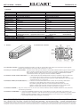
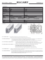
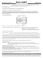
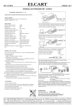
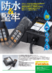
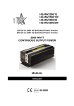
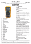
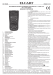
ART. 13/16600 - 13/16610
ELCART
PAGINA 1 DI 12
Manuale di istruzioni/Scheda tecnica
Manuale di istruzioni
ART. 13/16600 (12 VCC)
ART. 13/16610 (24 VCC)
2500W
INVERTER DI CORRENTE
DA CC A CA
Leggere attentamente questo manuale di istruzioni, prima di usare l’inverter
Contenuto
1. Specifiche
2. Struttura
2.1. Pannello Output e istruzioni
2.1.1. Interruttore ON/OFF
2.1.2 Presa per controllo a distanza ON/OFF
2.1.3. Indicatore VOLTS (tensione della batteria)
2.1.4. Indicatore AMPS (corrente della batteria)
2.1.5. Indicatore POWER (potenza)
2.1.6. Indicatore OVER TEMP (surriscaldamento)
2.1.7. Indicatore OVER LOAD (sovraccarico)
2.1.8. Indicatore Allarme
2.1.9. Presa AC
2.2. Utilizzo Input e istruzioni
2.2.1. Ventola
2.2.2. Connettore terminali / polo positivo(rosso,+) & polo negativo(nero,-)
2.2.3. Capocorda di terra del telaio
3. Istruzioni per l’utilizzo
3.1. Utilizzo
3.2. Carico
4. Installazione permanente
4.1. Dove installarlo
4.2. Come installarlo
4.3. Batteria consigliata
4.4. Cavi CC consigliati
5. Manutenzione
6. Guida alla ricerca ed eliminazione guasti
7. Attenzione
7.1. Non usate l’inverter 2500W con I seguenti dispositivi ricaricabili
7.2. Utilizzate il tipo e il formato di batteria corretti
7.3. Ricordatevi che l’invertitore deve essere installato in un ambiente adatto
Tensione uscita:
230 VA
2
3
3
3
3
3
3
3
3
4
4
4
4
4
4
5
5
5
6
6
6
6
6
6
7
7
8
8
8
9
Frequenza uscita: 50 HZ
ELCART DISTRIBUTION SPA via Michelangelo Buonarroti, 46 - 20093 Cologno Monzese (Milano) ITALY
Tel. +39 02.25117310 Fax +39 02.25117610 sito internet: www.elcart.com e-mail: [email protected]
La divulgazione dei dati contenuti in questa scheda è da ritenersi un servizio puramente informativo e non costituisce alcun vincolo da parte della Elcart in merito a prestazioni ed utilizzo del prodotto.
The divulgation of data contained on this technical sheet are exclusively for informational reasons and establish no link on behalf of Elcart regard to thr performances and the usa of the product.
La divulgacion de los datos contenidos en esta ficha son un servicio unicamente informativo y no constituyen ningun vinculo de parte de Elcart respecto a las prestaciones y uso del producto.
ART. 13/16600 - 13/16610
ELCART
Manuale di istruzioni/Scheda tecnica
PAGINA 2 DI 12
1. Specifiche
Spec.
DC12V ART. 13/16600
5000W di picco
Potenza in uscita
2500W continui
Tensione in ingresso
DC10 ~ 16V
Tensione in uscita
AC230V
Forma d’onda in uscita Onda sinusoidale modificata
Frequenza uscita
50 HZ
Corrente stand-by
<0.7A
Rendimento
85% ~ 90%
Protezione tensione
DC16V±0.5V
ingresso
Allarme batteria scarica DC10.5V±0.5V
Arresto per batteria
DC10±0.5V
scarica
Protezione
+60°C±5°C
surriscaldamento
Raffreddamento
La ventola s’avvia quando la temperatura raggiunge 40°C
Protezioni
Fusibile
Prese CA
Dimensioni (LxWxH)
Peso
2. Struttura:
ART. 13/16610
DC24V
5000W di picco
2500W continui
DC20 ~ 30V
AC230V
Onda sinusoidale modificata
50 HZ
<0.6A
85% ~ 90%
DC31V±0.8V
DC21±0.8V
DC20±0.8V
+60°C±5°C
La ventola s’avvia quando la temperatura raggiunge 40°C
* Alta tensione CC ingresso
* Cortocircuito
* Polarità invertita (con fusibile)
* Allarme batteria scarica * Spegnimento batteria scarica
* Sovraccarico
* Surriscaldamento
30A x 12 pezzi
15A x 12 pezzi
2
2
430x210x159mm
430x210x159mm
8,700 kg
8,700 kg
2.1. Pannello uscite e istruzioni:
2.1.1 Interruttore ON/OFF.... L’interruttore ON/OFF attiva/disattiva il circuito di controllo dell'inverter. Quando non usate l'inverter, potete spegnerlo
premendo questo interruttore, senza bisogno di disconnettere il cavo di rete.
2.1.2 Presa per controllo a distanza ON/OFF... L’inverter è dotato di una presa che interfaccia un interruttore ON/OFF a distanza (optional ART.13/15900).
Questo consente di collocare l'inverter fuori dalla vista e di accenderlo e spegnerlo mediante un pannello
per il controllo a distanza, montato in un posto comodo. Sul pannello, oltre all’interruttore ON/OFF,
c’è un indicatore luminoso che segnala se l'inverter è ACCESO o SPENTO.
2.1.3 Indicatore VOLTS (tensione della batteria)......... L’indicatore della tensione della batteria indica la tensione al terminale in ingresso dell'inverter.
Con correnti in ingresso basse, la tensione si avvicina molto alla tensione della batteria.
Con correnti in ingresso elevate, la tensione è inferiore a quella della batteria a causa della caduta
di tensione attraverso cavi e connessioni.
2.1.4 Indicatore AMPS (corrente della batteria)......... L’indicatore di corrente della batteria indica la corrente che l'inverter attinge dalla batteria.
Non indica la corrente attinta da altri carichi pur sempre connessi alla batteria.
Per un utilizzo prolungato dell'inverter, la corrente dovrebbe rimanere nella zona verde.
Quando la corrente è nella zona gialla, l'inverter può funzionare ancora per qualche minuto.
Quando la corrente è nella zona rossa, l'inverter va in protezione e si spegne.
2.1.5 Indicatore POWER........ Dopo aver connesso i cavi CC, uno aver acceso l'inverter, l'indicatore luminoso POWER si illumina in verde, ad indicare
che l'inverter è pronto all'uso.
2.1.6 Indicatore OVER TEMP........ L’indicatore OVER TEMP si illumina in giallo e suona l'allarme se l'inverter si surriscalda, va in protezione e poi
si spegne. L'inverter si surriscalda se viene fatto funzionare sopra il livello di potenza di 2500W, che è la potenza continua
dichiarata per l'utilizzo prolungato, oppure se è stato posto in un luogo dove il calore non riesce a disperdersi bene.
L’inverter riparte automaticamente non appena si è raffreddato.
ELCART DISTRIBUTION SPA via Michelangelo Buonarroti, 46 - 20093 Cologno Monzese (Milano) ITALY
Tel. +39 02.25117310 Fax +39 02.25117610 sito internet: www.elcart.com e-mail: [email protected]
La divulgazione dei dati contenuti in questa scheda è da ritenersi un servizio puramente informativo e non costituisce alcun vincolo da parte della Elcart in merito a prestazioni ed utilizzo del prodotto.
The divulgation of data contained on this technical sheet are exclusively for informational reasons and establish no link on behalf of Elcart regard to thr performances and the usa of the product.
La divulgacion de los datos contenidos en esta ficha son un servicio unicamente informativo y no constituyen ningun vinculo de parte de Elcart respecto a las prestaciones y uso del producto.
ART. 13/16600 - 13/16610
ELCART
Manuale di istruzioni/Scheda tecnica
PAGINA 3 DI 12
2.1.7.Indicatore OVER LOAD........L'indicatore OVER LOAD si illumina in rosso quando l'inverter si spegne in conseguenza di un pesante sovraccarico.
Per riavviare l'inverter, premete l'interruttore ON/OFF (oppure l'interruttore ON/OFF del telecomando), dopo aver
provveduto ad eliminare la causa del problema (riducendo o eliminando il carico).
2.1.8. Indicatore allarme........Un segnale sonoro si attiva col verificarsi di una delle seguenti circostanze:
a. Superamento temperatura
b. Allarme di batteria scarica (<10,5V per l'inverter da 2500W/12V, <21V per quello da 2500W/24V).
c. Spegnimento per esaurimento batteria (<10V per l'inverter da 2500W/12V, <20V per quello da 2500W/24V).
2.1.9. Presa CA........Potete connettere i vostri carichi CA direttamente a questa presa.
Attenzione: Quando eseguite una connessione CA permanente con l'inverter, considerate che tensioni di 110V o 220V CA possono essere mortali,
non lavorate su cablaggi CA connessi con l'inverter (nemmeno se l'inverter è spento) a meno che la fonte di corrente CC sia fisicamente
disconnessa dall'inverter. Non lavorate su cablaggi CA connessi a una fonte di energia CA come un generatore o la rete elettrica.
2.2. Pannello ingressi e istruzioni:
2.2.1 Ventola........disperde il calore che si genera all'interno dell'inverter durante il funzionamento.
2.2.2. Connettore terminali / polo positivo (rosso, +) polo negativo (nero, -)........
Il connettore terminali consente di connettere le estremità dei cavi CC con l'inverter, il filo rosso è connesso al polo positivo (rosso,+) il filo nero è connesso
al polo negativo (nero,-).
Mentre le altre estremità del cavo CC sono connesse con la batteria, il filo rosso va sempre con il polo positivo (rosso,+) e il filo nero con il polo negativo (nero,-).
Attenzione: Non invertite la polarità.
2.2.3. Capocorda di terra del telaio..... L’inverter ha un capocorda che si connette al telaio, quindi l'uscita CA dell'inverter è da connettere alla massa a terra
dell'impianto elettrico. Il filo di terra nella scatola di giunzione CA sul pannello uscite dell’inverter è connesso al telaio.
Il capocorda di terra del telaio deve essere connesso alla messa a terra, che è diversamente collocata a seconda di dove l’inverter è installato.
In un veicolo, il capocorda di terra del telaio è da connettere al telaio del veicolo.
In un’imbarcazione è da connettere all’impianto di messa a terra dell’imbarcazione.
Per impianti fissi, connettete la messa a terra a un asta di terra (un asta di metallo conficcata nel terreno), o ad idonei ingressi di terra già predisposti.
Per connettere il capocorda di terra del telaio alla messa a terra, usate un filo di rame #12AWG o di diametro maggiore (di preferenza con isolamento verde/giallo).
Il conduttore neutro (comune) del circuito uscita CA dell’inverter è connesso con la terra del telaio.
Quindi, quando il telaio viene connesso a terra, il conduttore neutro è messo a terra.
In questo modo vengono rispettate le normative nazionali in materia di strumentazione elettrica con fonti di corrente CA derivata separatamente
(come inverter e generatori), che stabiliscono che il conduttore neutro sia allacciato alla terra, come il conduttore neutro della linea elettrica che è allacciato
a terra al salvavita CA.
Attenzione: Non usate l'inverter da 4000W senza connetterlo alla massa a terra. C’è il rischio di prendere la scossa.
3. Istruzioni per l'utilizzo:
3.1. Utilizzo.... Per prima cosa, connettete stabilmente l’inverter alla batteria o ad altra fonte di corrente CC per mezzo di cavi CC dotati di terminali.
Fate attenzione alla polarità, connettete il polo positivo (rosso,+) sul pannello ingresso dell’inverter con il polo positivo (rosso,+) della batteria
o di altra fonte di corrente CC e il polo negativo (nero,-) sul pannello ingresso dell'inverter al polo negativo (nero,-) della batteria o di altra
fonte di corrente CC.
Attenzione: Non invertite la polarità. Se fate una connessione con la polarità invertita (col positivo al posto del negativo), bruciate il fusibile
e rischiate di danneggiare in modo permanente l’inverter. Non usate “coccodrilli” e assicuratevi sempre, prima di connettere la batteria o altra fonte
di corrente CC, che l’interruttore ON/OFF sul pannello uscita dell’inverter sia nella posizione OFF.
Attenzione: Non usate l'inverter collegandolo direttamente ad una fonte di ricarica come un alternatore o un pannello solare.
L’inverter per funzionare bene, deve essere connesso a una batteria o a un alimentatore CC che forniscano un adeguato quantitativo di corrente ben
stabilizzata.
Adesso l’inverter è in grado di fornire corrente CA ai vostri carichi.
Se avete più di un carico connesso, dopo aver acceso l'inverter, avviatene uno alla volta in modo che l'inverter non debba provvedere a soddisfare
contemporaneamente il fabbisogno iniziale di corrente di tutti i carichi.
Si raccomanda di collegare a terra l'inverter al telaio del vostro veicolo, imbarcazione, .....ecc. o al circuito di dispersione di terra di casa vostra
(oppure a un paletto conficcato in terra). Questa procedura consente di prevenire i rischi di scossa elettrica.
ELCART DISTRIBUTION SPA via Michelangelo Buonarroti, 46 - 20093 Cologno Monzese (Milano) ITALY
Tel. +39 02.25117310 Fax +39 02.25117610 sito internet: www.elcart.com e-mail: [email protected]
La divulgazione dei dati contenuti in questa scheda è da ritenersi un servizio puramente informativo e non costituisce alcun vincolo da parte della Elcart in merito a prestazioni ed utilizzo del prodotto.
The divulgation of data contained on this technical sheet are exclusively for informational reasons and establish no link on behalf of Elcart regard to thr performances and the usa of the product.
La divulgacion de los datos contenidos en esta ficha son un servicio unicamente informativo y no constituyen ningun vinculo de parte de Elcart respecto a las prestaciones y uso del producto.
ART. 13/16600 - 13/16610
ELCART
Manuale di istruzioni/Scheda tecnica
PAGINA 4 DI 12
3.2.Carico........Attenzione: Per evitare sovraccarico e surriscaldamento, non fate funzionare l’inverter se il carico connesso supera i 2500W,
e non utilizzatelo a lungo a pieno carico.
4. Installazione permanente:
4.1 Dove installarlo........Il luogo ideale dove installare l'invertitore deve essere:
a. Asciutto: fate attenzione che l'acqua non goccioli o schizzi sull'inverter.
b. Fresco: la temperatura ambiente deve essere compresa tra 0 ~ 25°C (32 ~ 77°F)
c. Ventilato: assicuratevi che l'inverter abbia la ventilazione necessaria, lasciate almeno 2,5cm (1”) di spazio libero attorno
per consentire il ricambio d'aria. Assicuratevi che le aperture per la ventilazione, una sul pannello uscite e l'altra sul
pannello ingressi, non siano ostruite.
Attenzione: Per evitare il surriscaldamento e per prevenire il rischio di incendio, non coprite o ostruite le aperture di ventilazione sull'inverter.
Lasciate sempre, attorno all'inverter un po’ di spazio libero per la ventilazione.
d. Sicuro: non collocate l'inverter in prossimità di sostanze infiammabili come benzina, gas, nitroglicerina, etc.
e. Vicino alla batteria: collocate l'inverter nelle vicinanze della batteria al fine di ridurre al minimo la lunghezza dei cavi CC, ma non accanto ad essa.
E’ preferibile e anche meno costoso avere fili CA che cavi CC più lunghi, perché nei fili CA la corrente è meno elevata.
Attenzione: Alcuni componenti sono soggetti a produrre archi o scintille, per prevenire incendi ed esplosioni, vi raccomandiamo di non collocare
l'inverter accanto a batterie o sostanze infiammabili.
4.2. Come istallarlo.........Montate l'inverter orizzontalmente o verticalmente su una superficie piatta usando le flangie apposite sul pannello uscite e su
quello ingressi. I tasselli utilizzati per il montaggio devono essere robusti e resistenti alla corrosione.
Fate attenzione che l'inverter non vi cada perché è un dispositivo elettrico sensibile e si potrebbe danneggiare.
4.3 Batteria consigliata........La resa dell'inverter dipende in gran parte dalla batteria, quindi è importante scegliere il tipo e le dimensioni di batteria corretti.
4.4. Cavi CC consigliati........Cavi e fili adeguati sono molto importanti per la sicurezza e il buon funzionamento dell'inverter.
Dato che l'inverter da 2500W ha un basso voltaggio e una corrente elevata, il cablaggio a bassa resistenza tra la batteria
e l'invertitore è determinante nel fornire il massimo apporto di energia utilizzabile per il carico connesso.
Non ha senso risparmiare sul cablaggio, dopo aver investito su batterie e inverter ad alto rendimento.
2500W/12V : #38 2Awg
2500W/24V : #22
4Awg
Attenzione: Non stagnare le etremità dei cavi,potrebbe indebolire la connessione.
Spellate 1,25cm ca. (1/2 ") di isolante all'estremità dei cavi CC da connettere all'inverter. Fissate un terminale ad anello (da 5/16") alle estremità dei fili
da collegare ai terminali CC sull'inverter. I terminali ad anello devono essere crimpati (stretti) con un attrezzo apposito.
Le altre estremità dei cavi devono essere saldamente connesse al connettore della batteria mediante terminali ad anello o simili.
Attenzione: Non stagnate le estremità dei cavi con lega di saldatura, non otterrete una buona connessione.
5. Manutenzione... Per mantenere l'inverter sempre in buono stato, pulitelo di tanto in tanto con un panno inumidito di alcool
(o semplicemente un panno umido) per evitare che polvere e sporco si accumulino.
La presa d'aria (ventola/aperture di ventilazione) sul pannello ingressi e le aperture per lo scarico dell'aria sul pannello uscite sono soggette
a sporcarsi. Si raccomanda una manutenzione e un controllo regolari, le viti sul terminale ingresso CC devono essere strette di tanto in tanto.
6. Guida alla ricerca ed eliminazione guasti:
Problemi
1. Bassa tensione in uscita
2. Bassa tensione in uscita e indicatore
AMPS nella zona rossa
3. Nessuna tensione in uscita e indicatore
VOLTS nella zona rossa inferiore
4. Nessuna tensione in uscita
e indicatore POWER spento
5. Nessuna tensione in uscita
e indicatore VOLTS nella
zona rossa superiore
Possibili cause
E’ stato utilizzato un
voltmetro a lettura media
Sovraccarico
Bassa tensione ingresso
Soluzioni
Usate un voltmetro di presisione a lettura reale RMS
Riducete il carico
Ricaricate la batteria, controllate le connessioni e i cavi
a. L’inverter è spento
Accendete l’inverter
b. Nessuna corrente all’
inverter
c. E’ saltato il fusibile
interno
d. Polarità CC invertita
Controllare la connessione tra l’inverter e la batteria
Chiedete ad un elettricista qualificato di controllare e sostituire il fusibile
Rivolgetevi ad un elettricista qualificato per controllare e sostituire il fusibile.
(rispettate la polarità)
Alta tensione in ingresso Assicuratevi che l’inverter sia connesso alla batteria da 12V
(24V per l’inverter da 4000W/24V) e controllate la regolarità del sistema di
ricarica batterie
a. Cavi CC non idonei
6. Allarme batteria scarica suona e
l’indicatore di VOLTS scende al di sotto di
10,5V (di 21V per l’inverter da 2500W/24V)
b. Batteria scarica
Usate cavi adatti e collegateli bene
Caricate la batteria o sostituitela
7. Assente la tensione in uscita, acceso
Spegnimento per
l’indicatore OVER TEMP, carico di
surriscaldamento
corrente in ingresso superiore a 2500W/250A
(a 125A per l’inverter da 2500W/24V)
Lasciate raffreddare l’inverter e riducete il carico in caso di utilizzo prolungato
8. Assente la tensione in uscita, acceso
Spegnimento per
l’indicatore OVER TEMP, carico di
surriscaldamento
corrente in ingresso inferiore a 2500W/250A
(a 125A per l’inverter da 2500W/24V)
Assicuratevi che le aperture per la ventilazione dell’inverter non siano ostruite
e riducete la temperatura ambiente
9. Assente la tensione in uscita, accesso
l’indicatore OVER LOAD
a. Cortocircuito o
Eliminate il cortocircuito, controllate la connessione CA e la polarità
connessione sbagliata
Carico di potenza
Rimuovete o riducete il carico
eccessivo
Attenzione: Se dopo aver eseguito la ricerca guasti di cui sopra, non riuscite a far funzionare l’inverter, inviatecelo per farlo controllare, o
fatelo controllare e riparare da un tecnico specializzato. Non prendete l'iniziativa di aprire da soli la cassa o di scollegare il cavo.
ELCART DISTRIBUTION SPA via Michelangelo Buonarroti, 46 - 20093 Cologno Monzese (Milano) ITALY
Tel. +39 02.25117310 Fax +39 02.25117610 sito internet: www.elcart.com e-mail: [email protected]
La divulgazione dei dati contenuti in questa scheda è da ritenersi un servizio puramente informativo e non costituisce alcun vincolo da parte della Elcart in merito a prestazioni ed utilizzo del prodotto.
The divulgation of data contained on this technical sheet are exclusively for informational reasons and establish no link on behalf of Elcart regard to thr performances and the usa of the product.
La divulgacion de los datos contenidos en esta ficha son un servicio unicamente informativo y no constituyen ningun vinculo de parte de Elcart respecto a las prestaciones y uso del producto.
ELCART
ART. 13/16600 - 13/16610
Manuale di istruzioni/Scheda tecnica
PAGINA 5 DI 12
7. Attenzione:
7.1. Non usate l'invertitore con i seguenti dispositivi ricaricabili........
Alcuni dispositivi ricaricabili contenenti piccole batterie al nichel cadmio possono subire danni se connessi all'inverter.
Due categorie in particolare sono soggette a questo inconveniente:
a. Piccoli dispositivi che funzionano a batteria come torce, rasoi e luci notturne che si caricano inserendoli direttamente nella presa CA.
b. Alcuni carica batterie per batterie che si montano su dispositivi portatili.
Su questi carica-batterie c'è un'etichetta che avverte della presenza di tensione pericolosa a livello dei terminali. Questo problema non si presenta con la
maggior parte dei dispositivi funzionanti a batteria, che in genere hanno un caricatore separato o un trasformatore da inserire nella presa CA.
Se sull'adattatore CA o sul caricatore è presente un etichetta che dichiara che l'uscita di tensione CA o CC è bassa (inferiore a 30V), si potrà connetterlo senza
problemi e in tutta sicurezza all'inverter.
7.2. Utilizzate il tipo e il formato di batteria corretti........ L’inverter da 12V può essere connesso solo a batterie con tensione nominale di 12V.
L’inverter da 12V non funziona con una batteria da 6V, e viene danneggiato se connesso a una batteria da 24V.
L’inverter da 24V deve necessariamente essere connesso solo a una batteria da 24V e non funziona con batterie da 6V o 12V.
Per la maggior parte degli impieghi dell'inverter da 4000W, vi consigliamo di usare una o più batterie a lunga durata in parallelo, per disporre di più
capacità e per non scaricare troppo le batterie.
7.3. Ricordatevi che l'inverter deve essere istallato in un ambiente:
a. Ben ventilato e con temperatura ambiente compresa tra 0 ~ 40°C (32 ~ 77°F)
b. Lontano da acqua, umidità, olio, benzina, gas e sostanze infiammabili.
c. Non esposto ai raggi solari o in prossimità di fonti di calore.
d. Fuori dalla portata dei bambini.
N.B.: Si declina ogni tipo di responsabilità per ogni uso improprio dell’apparecchio.
Pertanto, si esclude ogni forma di garanzia nel caso di: Utilizzi non conformi a quanto descritto nel manuale e/o specifiche del produttore ed in
particolare per ogni utilizzo che preveda una modifica della struttura e/o circuito dell’apparecchio.
Disegni e specifiche tecniche possono essere variati a discrezione del produttore senza alcun avviso.
Certificazione
L’apparecchio è certificato e13.
e13
Versioni, modifiche tecniche ed opzioni di consegna sono riservate.
Questo apparecchio è conforme a quanto stabilito dai seguenti Regolamenti CE:
“Direttiva sulla Bassa Tensione delle Apparecchiature Elettriche” 2006/95/EC.
“Direttiva sulla Compatibilità Elettromagnetica” 2004/108/EC.
ELCART DISTRIBUTION SPA via Michelangelo Buonarroti, 46 - 20093 Cologno Monzese (Milano) ITALY
Tel. +39 02.25117310 Fax +39 02.25117610 sito internet: www.elcart.com e-mail: [email protected]
La divulgazione dei dati contenuti in questa scheda è da ritenersi un servizio puramente informativo e non costituisce alcun vincolo da parte della Elcart in merito a prestazioni ed utilizzo del prodotto.
The divulgation of data contained on this technical sheet are exclusively for informational reasons and establish no link on behalf of Elcart regard to thr performances and the usa of the product.
La divulgacion de los datos contenidos en esta ficha son un servicio unicamente informativo y no constituyen ningun vinculo de parte de Elcart respecto a las prestaciones y uso del producto.
ART. 13/16600 - 13/16610
ELCART
PAGINA 6 DI 12
Manuale di istruzioni/Scheda tecnica
INVERTER AD ONDA SINUSOIDALE PURA O MODIFICATA?
L’inverter giusto dipende dalla potenza assorbita e dal tipo di utenze connesse.
*OL LQYHUWHU GHOOD JDPPD 9,&725< RIIURQR XQD WHQVLRQH G·XVFLWD PRGLÀFDWD
VXIÀFLHQWHSHUODPDJJLRUSDUWHGHOOHXWHQ]HFRQXQDPSLRFDPSRGLWHQVLRQHGL
LQJUHVVRDVFLXJDFDSHOOLWUDSDQRIRUQREROOLWRUH
'LVSRVLWLYL SL HYROXWL HVWUHPDPHQWH VHQVLELOL FRQ UHTXLVLWL GL DYYLDPHQWR
SDUWLFRODULDGHVDSSDUHFFKLDXGLRYLGHR79UDGLR/&'PRWRULHOHWWULFLVSHVVR
reagiscono agli sbalzi di tensione con interferenze o guasti.
,QTXHVWRFDVRODVFHOWDQHFHVVDULDqODVHULHDGRQGDVLQXVXRLGDOHSXUD
OOPDVVLPRGHOO·DIÀGDELOLWjHGHOOHSUHVWD]LRQLqUDSSUHVHQWDWDGDOODVHULHGLLQYHUWHU
FKHSUHVHQWDQRXQDWHQVLRQHGLXVFLWDVLQXVRLGDOHSXUDSHUIHWWDPHQWH
adatta all’utilizzo in applicazioni professionali.
6ROLWDPHQWHqO·DVVRUELPHQWRDGHWHUPLQDUHODVFHOWDGHOWLSRGLLQYHUWHU
7XWWDYLDXQVRORGLVSRVLWLYRFKHQHFHVVLWDGLXQDWHQVLRQHVLQXVRLGDOHDRQGDSXUD
qXQDUDJLRQHVXIÀFLHQWHSHUVFHJOLHUHXQLQYHUWHUDRQGDSXUD
Nella scelta si dovrebbe tenere in considerazione l’assorbimento maggiore derivato
dallo spunto di accensione.
)ULJRULIHULFRPSUHVVRULHODPSDGHDOQHRQSRVVRQRFRQVXPDUHÀQRDYROWHLQ
più del loro assorbimento medio.
Un aiuto nella scelta
Utenza
Potenza nominale
Qualità della tensione d’uscita
0DFFKLQDGDFDIIpÀOWUR
:DWW
2QGDVLQXVRLGDOHPRGLÀFDWD
0DFFKLQDGDFDIIpFLDOGH
:DWW
Onda sinusoidale pura
Macchina da caffé
:DWW
Onda sinusoidale pura
)RUQRDPLFURRQGH
:DWW
2QGDVLQXVRLGDOHPRGLÀFDWD
7RVWDSDQH
:DWW
2QGDVLQXVRLGDOHPRGLÀFDWD
%ROOLWRUH
:DWW
2QGDVLQXVRLGDOHPRGLÀFDWD
/DPSDGDGLOHWWXUD
:DWW
2QGDVLQXVRLGDOHPRGLÀFDWD
/DPSDGDDEDVVRFRQVXPR
:DWW
Onda sinusoidale pura
/DPSDGDDOQHRQ
:DWW
Onda sinusoidale pura
$SSDUHFFKLRDXGLRYLGHR
:DWW
Onda sinusoidale pura
&RPSXWHUSRUWDWLOH
:DWW
2QGDVLQXVRLGDOHPRGLÀFDWD
7UDSDQRVHJDFLUFRODUH
:DWW
2QGDVLQXVRLGDOHPRGLÀFDWD
$VSLURSROYHUH
:DWW
2QGDVLQXVRLGDOHPRGLÀFDWD
6SD]]ROLQRHOHWWULFR
:DWW
Onda sinusoidale pura
1RQqVHPSUHFRQVLJOLDELOHLQFDVRGLXWHQ]HVHQVLELOL
3HUDOFXQLGLVSRVLWLYLqFRQVLJOLDELOHXQDWHQVLRQHVLQXVRLGDOHSXUD
9ROWDJJLRDRQGDVLQXVRLGDOHPRGLÀFDWDRSXUD
2QGDVLQXVRLGDOHPRGLÀFDWD
/DFXUYDGHOODWHQVLRQHDGRQGDPRGLÀFDWDqFDUDWWHUL]]DWDGDXQRQGDTXDGUDWDVLPLOHDGXQRQGDVLQXVRLGDOH
5LVXOWDWRXQDWHQVLRQHG·XVFLWDVWDELOHSHUIUHTXHQ]DHDPSLH]]D
2QGDVLQXVRLGDOHSXUD
/DFXUYDGHOODWHQVLRQHqFDUDWWHUL]]DWDGDXQ·RQGDVLQXVRLGDOHSHUIHWWD
5LVXOWDWRXQDFXUYDVLQXVRLGDOHSXUDFRPHTXHOODGHOODUHWHGRPHVWLFD
Informazioni agli utenti
Il simbolo riportato sull’apparecchiatura indica che il rifiuto deve essere oggetto di
“raccolta separata”.
Pertanto, l’utente dovrà conferire (o far conferire) il rifiuto ai centri di raccolta differenziata
predisposti dalle amministrazioni comunali, oppure consegnarlo al rivenditore contro
acquisto di una nuova apparecchiatura di tipo equivalente.
La raccolta differenziata del rifiuto e le successive operazioni di trattamento, recupero
e smaltimento favoriscono la produzione di apparecchiature con materiali riciclati e
limitano gli effetti negativi sull’ambiente e sulla salute eventualmente causati da una
gestione impropria del rifiuto.
Lo smaltimento abusivo del prodotto da parte dell’utente comporta l’applicazione delle
sanzioni amministrative di cui l’articolo 50 e seguenti del D. Lgs. N° 22/1997.
IMPORTATO E DISTRIBUITO DA
ELCART DISTRIBUTION SPA
Via Michelangelo Buonarroti, 46
20093 COLOGNO MONZESE (MI)
ITALY
www.elcart.com - [email protected]
Made in Taiwan
ELCART DISTRIBUTION SPA via Michelangelo Buonarroti, 46 - 20093 Cologno Monzese (Milano) ITALY
Tel. +39 02.25117310 Fax +39 02.25117610 sito internet: www.elcart.com e-mail: [email protected]
La divulgazione dei dati contenuti in questa scheda è da ritenersi un servizio puramente informativo e non costituisce alcun vincolo da parte della Elcart in merito a prestazioni ed utilizzo del prodotto.
The divulgation of data contained on this technical sheet are exclusively for informational reasons and establish no link on behalf of Elcart regard to thr performances and the usa of the product.
La divulgacion de los datos contenidos en esta ficha son un servicio unicamente informativo y no constituyen ningun vinculo de parte de Elcart respecto a las prestaciones y uso del producto.
ELCART
ART. 13/16600 - 13/16610
PAGINA 7 DI 12
Manuale di istruzioni/Scheda tecnica
Instruction
Manual
ART. 13/16600 (12 VDC)
ART. 13/16610 (24 VDC)
2500 W
DC to AC POWER INVERTER
Please read this user manual in detail before use
Table of contents
1. Specification
2. Structure
2.1. Output panel and instruction
2.1.1. ON/OFF switch
2.1.2 Remote ON/OFF jack
2.1.3. VOLTS (battery voltage) indicator
2.1.4. AMPS(battery current) indicator
2.1.5. POWER indicator
2.1.6. OVER TEMP indicator
2.1.7. OVER LOAD indicator
2.1.8. Alarm indicator
2.1.9. AC outlet
2.2. Input panel and instruction
2.2.1. Fan
2.2.2. Terminal connector / positive pole(red,+) & negative pole(black,-)
2.2.3. Chassis ground lug
3. Operating instruction
3.1. Operating
3.2. Load
4. Permanent installation
4.1. Where to install
4.2. How to install
4.3. Battery recommended
4.4. DC cable recommended
5. Maintenance
6. Trouble shooting guide
7. Caution
7.1. Don’t use the 4000W inverter with the following rechargeable appliances
7.2. Use the correct size and type of battery
7.3. Always place this inverter in an environment as following
AC output voltage :
230 V
Output frequency :
50 HZ
7
7
7
7
7
7
7
7
7
8
8
8
8
8
8
8
8
8
9
9
9
9
9
9
9
9
10
10
10
10
ELCART DISTRIBUTION SPA via Michelangelo Buonarroti, 46 - 20093 Cologno Monzese (Milano) ITALY
Tel. +39 02.25117310 Fax +39 02.25117610 sito internet: www.elcart.com e-mail: [email protected]
La divulgazione dei dati contenuti in questa scheda è da ritenersi un servizio puramente informativo e non costituisce alcun vincolo da parte della Elcart in merito a prestazioni ed utilizzo del prodotto.
The divulgation of data contained on this technical sheet are exclusively for informational reasons and establish no link on behalf of Elcart regard to thr performances and the usa of the product.
La divulgacion de los datos contenidos en esta ficha son un servicio unicamente informativo y no constituyen ningun vinculo de parte de Elcart respecto a las prestaciones y uso del producto.
ART. 13/16600 - 13/16610
ELCART
PAGINA 8 DI 12
Manuale di istruzioni/Scheda tecnica
1. Specification
Spec.
Output power
Input voltage
Output voltage
Output waveform
Output frequency
Stand by current
Efficiency
High voltage input
shutdown
Battery low alarm
Battery low shutdown
Thermal protect
Cooling
Protections
Fuse
AC outlet
Size ( L*W*H )
Weight
2. Structure :
DC12V ART. 13/16600
2500W continue 5000W surge output
DC10 ~ 16V
AC230V
Modified sine wave
50 HZ
<0.7A
85% ~ 90%
DC16V±0.5V
DC24V ART. 13/16610
2500W continue 5000W surge output
DC20 ~ 30V
AC230V
Modified sine wave
50 HZ
<0.6A
85% ~ 90%
DC31V±0.8V
DC10.5V±0.5V
DC10±0.5V
+60°C±5°C
Fan start when the temperature reach 40°C
DC21±0.8V
DC20±0.8V
+60°C±5°C
Fan start when the temperature teach 40°C
* output short
* battery low alarm
30A * 12pcs
Two
430*210*159mm
8.700 kgs
* input polarity reverse(by fuse)
* battery low shutdown
* high DC input voltage
* over load
15A * 12pcs
Two
430*210*159mm
8.700 kgs
* over temperature
2.1. Output panel :
2..1.1. ON/OFF switch …….. The ON/OFF switch turns the control circuit in the inverter on, off.
It doesn’t need to be disconnected power from the inverter when you don’t use.
2.1.2. Remote ON/OFF jack …….. The inverter has a jack which interfaces with the optional remote ON/OFF switch, it allows you to mount the inverter
out of sight and turn ON or OFF from a conveniently located panel (remote control panel).
It also has ON/OFF switch and indicator light showing that the inverter is ON or OFF on the remote control panel.
2.1.3. VOLTS (battery voltage) indicator …….. The battery voltage indicator displays the voltage at the input terminal of the inverter.
At low currents input, the voltage is very close to the battery voltage. At high current input, the voltage
will be lower than the battery voltage because of the voltage drop across the cables and connections.
2.1.4. AMPS ( battery current ) indicator …….. The battery current indicator displays the current drawn from the battery by the inverter.
It won’t indicate current drawn by other load also connected to the battery.
Current should be in the green zone for continuous operation.
The inverter will operate for several minutes when current is at the yellow zone.
If the current is at the red zone, it will result in protective to shut down the inverter.
2.1.5. POWER indicator …….. After you connected the DC cables each with the battery and the inverter and switched on the inverter, the power indicator
illuminates w/green color, it indicates ready for use.
2.1.6. OVER TEMP indicator …. The OVER TEMP indicator illuminates w/yellow color and the alarm sound when the inverter overheated and shutdown.
The reason for the inverter overheated that it has been operated with the power levels above its 4000W continuous output
rating, or installed in a location which doesn’t allow it to dissipate heat properly.
The inverter will restart automatically once it has cooled.
ELCART DISTRIBUTION SPA via Michelangelo Buonarroti, 46 - 20093 Cologno Monzese (Milano) ITALY
Tel. +39 02.25117310 Fax +39 02.25117610 sito internet: www.elcart.com e-mail: [email protected]
La divulgazione dei dati contenuti in questa scheda è da ritenersi un servizio puramente informativo e non costituisce alcun vincolo da parte della Elcart in merito a prestazioni ed utilizzo del prodotto.
The divulgation of data contained on this technical sheet are exclusively for informational reasons and establish no link on behalf of Elcart regard to thr performances and the usa of the product.
La divulgacion de los datos contenidos en esta ficha son un servicio unicamente informativo y no constituyen ningun vinculo de parte de Elcart respecto a las prestaciones y uso del producto.
ART. 13/16600 - 13/16610
ELCART
Manuale di istruzioni/Scheda tecnica
PAGINA 9 DI 12
2.1.7. OVER LOAD indicator …….. The OVER LOAD indicator illuminates w/red color when the inverter shutdown because of a severe over load.
For restart the inverter, please switch the ON/OFF switch (or ON/OFF switch on the remote control panel) to OFF,
and correct the fault condition (remove or reduce the load), the switch back to ON.
2.1.8. Alarm indicator …….. An audible alarm will sound when any of the following conditions occurs:
a. Over temperature condition.
b. Low battery alarm (<10.5V for 2500W/12V inverter, <21V for 2500W/24V inverter).
c. Low battery shutdown (<10V for 2500W/12V inverter, <20V for 2500W/24V inverter).
2.1.9. AC outlet …….. You can plug your AC loads directly into this outlet.
Caution: If making a permanent AC connection to the inverter, please attend to 110V or 220V AC power is potentially lethal,
don’t work on AC wiring while the wiring is connected to the inverter (even if it is switched off) unless the DC power source is
physically disconnected from the inverter. Also don’t work on AC wiring if it is connected to another AC power source such as a
generator or the utility line.
2.2. Input panel and instruction:
2.2.1. Fan …….. The fan disperses the inverter internal heat during the inverter operating .
2.2.2. Terminal connector/positive pole (red, +) & negative pole (black , -) … The terminal connector allows you to connect the ends of DC cables
with the inverter, red wire is connected with positive pole (red, +)
and black wire is connected with negative pole (black, -).
And the other ends of DC cables connected with battery, also the red wire
with positive pole (red, +) and the black wire with negative pole (black, -).
Caution: Please don’t reverse the polarity.
2.2.3. Chassis ground lug .... The inverter has a lug which is to connect the chassis of the inverter, therefore, the inverter’s AC output ground to you AC
distribution system ground. The ground wire in the AC junction box on the output panel of the inverter is connected to the chassis.
The chassis ground lug must be connected to a grounding point, which will very depending on where the inverter is installed. In a vehicle, connect the chassis
ground lug to the chassis of the vehicle. In a boat, connect to the boat’s grounding system. In a fixed location, connect to earth ground by a ground rod
(a metal rod pounded into the earth), or other proper service entrance ground. Use a # 12 AWG or larger copper wire (preferably with green/yellow insulation)
to connect the chassis ground lug to the grounding point. The neutral (common) conductor of the inverter’s AC output circuit is connected to chassis ground.
Therefore, when the chassis is connected to ground, the neutral conductor will also be grounded. This conforms to national electrical code requirements that
separately derived AC sources (such as inverters and generators) have their neutral conductors tied to ground in the same way that the neutral conductor from
the utility line is tied to ground at the AC breaker panel.
Caution: Don’t operate the 4000W inverter with out connecting it to ground. Electrical shock hazard may result.
3. Operating instruction:
3.1. Operating …….. Firstly, please connect the inverter tightly to your battery or other DC power source by DC cable with terminals.
Please attend to the polarity, connect the positive pole (red, +) on the input panel of the inverter to the positive pole (red, +)
of the battery or other DC power source and the negative pole (black, -) on the input panel of the inverter to the negative pole (black, -)
of the battery or other DC power source.
Caution: Please don’t reverse the polarity.
If reverse polarity connection (positive to negative), it will blow the fuses in the inverter and may permanently damage the inverter.
Please don’t use “alligator” clips and always ensure the ON/OFF switch on the output panel of the inverter is switched to the OFF position before
connected the battery or other DC power source.
Caution: Please don’t operate the inverter directly from a charging source such as an alternator or a solar panel. It must be connected to a battery
or a well-regulated and high-current DC power supply to work properly.
The inverter is now ready to deliver AC power to your loads. If you are operating several load from the inverter, turn them on separately after the inverter
already turned on. This will ensure that the inverter doesn’t have to deliver the starting currents for all the loads at once.
It is recommended that you earth the inverter to the chassis of your vehicle, boat, etc. or to your earth leakage circuit in a house (or a stake in the ground).
This step will avoid and electrical safety hazard.
ELCART DISTRIBUTION SPA via Michelangelo Buonarroti, 46 - 20093 Cologno Monzese (Milano) ITALY
Tel. +39 02.25117310 Fax +39 02.25117610 sito internet: www.elcart.com e-mail: [email protected]
La divulgazione dei dati contenuti in questa scheda è da ritenersi un servizio puramente informativo e non costituisce alcun vincolo da parte della Elcart in merito a prestazioni ed utilizzo del prodotto.
The divulgation of data contained on this technical sheet are exclusively for informational reasons and establish no link on behalf of Elcart regard to thr performances and the usa of the product.
La divulgacion de los datos contenidos en esta ficha son un servicio unicamente informativo y no constituyen ningun vinculo de parte de Elcart respecto a las prestaciones y uso del producto.
ELCART
ART. 13/16600 - 13/16610
Manuale di istruzioni/Scheda tecnica
PAGINA 10 DI 12
3.2. Load …….. Caution: Please don’t operate this inverter with load in excess of 2500W or full load for extended period of time to avoid overload
or over temperature.
4. Permanent installation:
4.1. Where to install ….. The inverter should be installed in a location that meets the following requirements:
a. Dry: Don’t allow water to drip or splash on the inverter.
b. cool: Ambient air temperature should be kept between 0 ~ 25°C (32 ~ 77°F)
c. Ventilated: ensure that the inverter in a compartment which is ventilated and you need to allow at least 1 inch (2.54 cm)
of clearance around the inverter for air flow. Ensure that ventilation openings one the output panel and input panel aren’t obstructed.
Caution: For reduce the fire hazard and avoid the overheating, please don’t cover or obstruct ventilation openings of the inverter.
And don’t put it in a zero clearance compartment.
d. Safe: Don’t install the inverter in the same compartment of storing flammable matters such as gasoline, gas, nitroglycerin, ………. etc.
e. Close to battery: install the inverter as close to battery as possible in order to minimize the length of DC cables, but don’t put in the same compartment.
It is better and cheaper to run loner AC wires than longer DC cables, because of the much lower current is the AC wires.
Caution: Some components of the inverter tend to produce arcs or sparks, for reduce risk of fire and explosion, please don’t install the in verter in
the compartment containing batteries and flammable matters and flammable matters.
4.2. How to install ….. Mount the inverter horizontally or vertically on a flat surface using the mounting flanges on the output panel and input panel.
Mounting hardware should be corrosion resistance and larger. Never drop the inverter as it is a sensitive electrical product and
damage will occurs.
4.3. Battery recommended …….. The battery you use strongly affects the performance you can expect from the inverter, it is very important to correct
size and type of battery.
4.4. DC cable recommended …….. Proper wire and wiring is very important for the safe and proper operating of the inverter.
Because the 2500W inverter has a low voltage, high current input, low resistance wiring between the battery and the inverter
is essential to deliver the maximum amount of usable energy to your load.
Don’t waste the investment you have made in batteries and a highly efficient inverter by using undersized wires.
2500W/12V : #38
2Awg
2500W/24V : #22
4Awg
Caution : Don’t tin the cable ends with solder owing to it will result in a poor connection .
5. Maintenance …….. For always keep the inverter operating normally, please clean the exterior of the unit periodically with a alcoholic cloth
(or damp cloth) to prevent accumulation of dust and dirt. The air intake (fan/ventilation openings) on the input panel and air exhaust
slots on the output panel is especially prone to accumulate dust and dirt.
A regular maintenance check is recommended, and the screws on the DC input terminals shoud be tightened periodically.
6. Trouble shooting guide :
Problems
1. Low voltage output
Possible causes
Solutions
Using an average reading voltmeter Use true RMS reading meter
2. Low voltage output and
AMPS indicator in red zone
Overload
Reduce load
3. No voltage output and VOLTS
indicator in lower red zone
4. No voltage output and
POWER indicator no light
Low voltage input
Recharge battery, check connections and cable
a. Inverter switched off
b. No power to inverter
c. Internal fuse open
Turn inverter on
Check wiring to inverter and battery
Have qualified electrician to check and replace
Have qualified electrician to check replace fuse,
please observe correct polarity
d. Reverse DC polarity
5. No voltage output and VOLTS
indicator in upper red zone
High voltage input
Make sure that inverter is connected to 12V battery
(24V for 2500W/24V inverter) and check regulation of charging system
6. Low battery alarm on all the time
and VOLTS indicator below 10.5V
(21V for 2500W/24V inverter)
a. poor DC wiring
Use proper cable and make solid connections
b Poor battery condition
Change battery or use new battery
7. No voltage output, OVER TEMP
indicator light and load in excess of
2500W/250A current input
(or 125A for 2500W/24V inverter)
Thermal shutdown
Allow inverter cool down and reduce
load if continuous operation required
8. No voltage output, OVER TEMP
indicator light and load less than
2500W/250 A current input
(or 125A for 2500W/24V inverter)
Thermal shutdown
Make sure ventilation openings in
inverter obstructed and reduce ambient temperature.
9. No voltage output and OVER LOAD a. Short circuit or wiring
indicator light
error
Check AC wiring for short circuit or
improper polarity
Caution: If after the above easy troubleshooting, this inverter still doesn’t work, please return it to us or have a qualified electrician to check and replace.
Don’t open the case or cut out the cord br youself.
ELCART DISTRIBUTION SPA via Michelangelo Buonarroti, 46 - 20093 Cologno Monzese (Milano) ITALY
Tel. +39 02.25117310 Fax +39 02.25117610 sito internet: www.elcart.com e-mail: [email protected]
La divulgazione dei dati contenuti in questa scheda è da ritenersi un servizio puramente informativo e non costituisce alcun vincolo da parte della Elcart in merito a prestazioni ed utilizzo del prodotto.
The divulgation of data contained on this technical sheet are exclusively for informational reasons and establish no link on behalf of Elcart regard to thr performances and the usa of the product.
La divulgacion de los datos contenidos en esta ficha son un servicio unicamente informativo y no constituyen ningun vinculo de parte de Elcart respecto a las prestaciones y uso del producto.
ART. 13/16600 - 13/16610
ELCART
Manuale di istruzioni/Scheda tecnica
PAGINA 11 DI 12
7. Caution:
7.1. Don’t use the inverter wiyh the following rechargeable appliance…
Certain recharges for small nickel cadmium batteries can be damaged if
connected to the inverter. Two particular types of equipment are prone to this problem:
a. Small battery operated appliances such as flashlights, razors and nightlights that can be plugged directly into the AC receptacle to recharge.
b. Certain battery chargers for battery packs used in hand power tools.
These chargers will have a warning label starting that dangerous voltages are present at the battery terminals.
This problem doesn’t occur with the vast majority of battery operating equipment.
Most of these equipments use a separate charger or transformer that is plugged into the AC receptacle and produces the lower voltage output.
If the label on the AC adaptor or charger states that produces the low AC or DC voltage output (less than 30 volts), the inverter will power this adaptor or
charger safely without trouble.
7.2. Use the correct size and type of battery ...
The 12V inverter must be connected only to battery with a nominal output voltage of 12V volts.
The 24V inverter won’t operate from a 6 volts battery, and will be damaged if it connected to a 24 volts battery.
The 24V inverter must be connected only to a 24 volts battery, and won’t operate from a 6 or 12 volts battery.
For most applications of 2500W inverter, we recommend that you use on or more deep cycle batteries in parallel.
More capacity is better since you will have more reserve capacity and your battery won’t be discharged as deeply.
7.3. Always place this inverter in an environment as following:
a. Well ventilated and ambient air temperature should be kept between 0 ~ 25°C (32 ~ 77°F)
b. Stay away from water, moisture, oil, gasoline, gas and any flammable matters.
c. Don’t expose directly to sunlight and place near the heat sources.
d. Keep out of reach of children.
The producer disclaims any kind of liability might arise from the improper use of the device.
Therefore, no warranty is provided, for example, in the following circumstances:
-use or employment of the product not consistent with what is set forth in the instruction manual
and or in the data sheetof the producer;
-modification and or tempering of the device.
Technical drawings anddata sheetmay be changed by the producer without any notice.
Approval
e13
The device has e13 approval.
Versions, technical modifications and delivery options reserved.
This device conforms to the following EC guidelines:
* “Low Voltage Electrical Equipment Directive” 2006/95/EC.
* “Electromagnetic Compatibilty Directive” 2004/108/EC.
ELCART DISTRIBUTION SPA via Michelangelo Buonarroti, 46 - 20093 Cologno Monzese (Milano) ITALY
Tel. +39 02.25117310 Fax +39 02.25117610 sito internet: www.elcart.com e-mail: [email protected]
La divulgazione dei dati contenuti in questa scheda è da ritenersi un servizio puramente informativo e non costituisce alcun vincolo da parte della Elcart in merito a prestazioni ed utilizzo del prodotto.
The divulgation of data contained on this technical sheet are exclusively for informational reasons and establish no link on behalf of Elcart regard to thr performances and the usa of the product.
La divulgacion de los datos contenidos en esta ficha son un servicio unicamente informativo y no constituyen ningun vinculo de parte de Elcart respecto a las prestaciones y uso del producto.
ELCART
ART. 13/16600 - 13/16610
PAGINA 12 DI 12
Manuale di istruzioni/Scheda tecnica
PURE SINE WAVE OR MODIFIED SINE WAVE INVERTER?
7KHEHVWFKRLFHIRULQYHUWHULQVWDOODWLRQVGHSHQGVRQSRZHUDEVRUSWLRQDQGWKHW\SH
of connected appliances.
7KH9,&725<UDQJHRILQYHUWHUVRIIHUVHQRXJKPRGLÀHGHQHUJ\RXWSXWFDSDEOHRI
RSHUDWLQJDZLGHYDULHW\RIORDGVHOHFWURQLFDQGKRXVHKROGLWHPVDVKDLUGU\HUV
GULOOV RYHQ ERLOHU HWF 3XUH VLQH ZDYH LQYHUWHUV DUH XVHG WR RSHUDWH VHQVLWLYH
HOHFWURQLF GHYLFHV WKRVH UHTXLUH KLJK TXDOLW\ RI ZDYHIRUP IRU OLWWOH KDUPRQLF
GLVWRUWLRQ VXFK DV DXGLR RU YLGHR HTXLSPHQW79 UDGLR /&' VSHHG PRWRUV ,Q
WKHVHFDVHV\RXQHHGWRVHOHFWWKHSXUHVLQHZDYHVHULHV
3XUH VLQH ZDYH LQYHUWHUV DUH LQGXVWU\ VWDQGDUG LQYHUWHUV WKDW RIIHU FRQWLQXRXV
SRZHUUDWHVWRVXLWHYHQSURIHVVLRQDOGHPDQGV
7KH VSHFLDO HOHFWURQLF GHVLJQ PDNHV WKHP FDSDEOH RI GULYLQJ LQGXFWLYH ORDGV
HOHFWULFWRROVDQGDSSOLDQFHV6SHFLÀFFKDVVLVIRUKDUVKHQYLURQPHQWVLVRQHRIWKH
PDLQIHDWXUHVRIWKHVHUHOLDEOHLQYHUWHUV
,W
VVDIHWRVD\DQ\HOHFWURQLFGHYLFHWKDWUHTXLUHVVHQVLWLYHFDOLEUDWLRQFDQRQO\EH
XVHGZLWKSXUHVLQHZDYHLQYHUWHUV)RUPDQ\HOHFWURQLFGHYLFHVWKDWGRQ
WUHTXLUH
VHQVLWLYHFDOLEUDWLRQPRGLÀHGVLQHZDYHLQYHUWHUVDUHDPRUHFRVWHIIHFWLYHRSWLRQ
7KH PRVW LPSRUWDQW LV FRQVLGHULQJ WKH PD[LPXP SRZHU DEVRUSWLRQ DQG VWDUWXS
5HIULJHUDWRUVFRPSUHVVRUVRUQHRQODPSVDUHDEOHWRH[FHHGWKHLUUDWHGZDWWDJHXS
WRWLPHVGXULQJVWDUWXS
0DNHWKHULJKWFKRLFH
'HYLFHV
3RZHUUDWLQJ
4XDOLW\RIRXWSXWYROWDJH
&RIIHHPDNHUÀOWHU
:DWW
0RGLÀHGVLQHZDYHYROWDJH
&RIIHHPDNHUSDGV
:DWW
3XUHVLQHZDYHYROWDJH
(VSUHVVRPDFKLQH
:DWW
3XUHVLQHZDYHYROWDJH
0LFURZDYHRYHQ
:DWW
0RGLÀHGVLQHZDYHYROWDJH
7RDVWHU
:DWW
0RGLÀHGVLQHZDYHYROWDJH
%RLOHU
:DWW
0RGLÀHGVLQHZDYHYROWDJH
5HDGLQJODPS
:DWW
0RGLÀHGVLQHZDYHYROWDJH
/RZFRQVXPSWLRQOLJKW
:DWW
3XUHVLQHZDYHYROWDJH
1HRQODPS
:DWW
3XUHVLQHZDYHYROWDJH
$XGLRYLGHRGHYLFH
:DWW
3XUHVLQHZDYHYROWDJH
0RELOHODSWRS
:DWW
0RGLÀHGVLQHZDYHYROWDJH
3RZHU'ULOO&LUFXODU6DZ
:DWW
0RGLÀHGVLQHZDYHYROWDJH
9DFXXP&OHDQHU
:DWW
0RGLÀHGVLQHZDYHYROWDJH
(OHFWULF7RRWKEUXVK
:DWW
3XUHVLQHZDYHYROWDJH
1RWDOZD\VVXLWDEOHIRUVHQVLWLYHDSSOLDQFHV
)RUVDPHGHYLFHVDSXUHVLQHZDYHLVVXLWDEOH
3XUHRUPRGLÀHGVLQHZDYH$&RXWSXW
0RGLÀHGVLQHZDYHPRGLÀHGVTXDUHZDYHRUVWHSZDYH
7KHYROWDJHSURGXFHVDVWHSSHGFXUYHGVLPXODWLQJDVLQHZDYH
7KHUHVXOWDQRXWSXWYROWDJHRIVWDEOHDPSOLWXGHDQGIUHTXHQF\
3XUHVLQHZDYH
7KHYROWDJHLVDFFXUDWHO\FRQWUROOHG
7KHUHVXOWDFOHDQVLQHZDYHYROWDJHOLNHWKDWIURPDKRPH
Information for users:
The symbol on the equipment indicates that the waste must be “separately collected”.
Therefore, the user must carry (or have it carried) the waste to the separately collected
waste centers set up by local governments, or deliver it to the dealer against purchase
of a new equivalent-type equipment.
The separate waste collection and the subsequent processing, recovery and disposal
operations favour the production of equipment with recycled materials and limit the
negative effects on the environment and on health which may be possibly caused by
the waste improper management.
The improper product disposal by the user causes the application of administrative
sanctions according to the Art. 50 et. seq. of the Law Decree No. 22/1997.
IMPORTED AND DISTRIBUTED BY:
ELCART DISTRIBUTION SPA
Via Michelangelo Buonarroti, 46
20093 COLOGNO MONZESE (MI)
ITALY
www.elcart.com - [email protected]
Made in Taiwan
ELCART DISTRIBUTION SPA via Michelangelo Buonarroti, 46 - 20093 Cologno Monzese (Milano) ITALY
Tel. +39 02.25117310 Fax +39 02.25117610 sito internet: www.elcart.com e-mail: [email protected]
La divulgazione dei dati contenuti in questa scheda è da ritenersi un servizio puramente informativo e non costituisce alcun vincolo da parte della Elcart in merito a prestazioni ed utilizzo del prodotto.
The divulgation of data contained on this technical sheet are exclusively for informational reasons and establish no link on behalf of Elcart regard to thr performances and the usa of the product.
La divulgacion de los datos contenidos en esta ficha son un servicio unicamente informativo y no constituyen ningun vinculo de parte de Elcart respecto a las prestaciones y uso del producto.