1
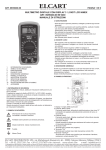
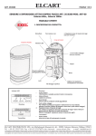
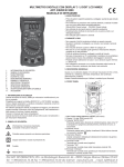
ELCART
ART. 9/9100
Manuale di istruzioni/Scheda tecnica
PAGINA 1 DI 8
MULTIMETRO DIGITALE COMPATTO NIMEX ART. 9/9100 NI 9100
MANUALE DI ISTRUZIONI
1.1 INFORMAZIONI PRELIMINARI
1.1.1 Durante l’utilizzo dello strumento, l’utente deve osservare tutte le
normali regole di sicurezza riguardo:
* Protezione contro i pericoli legati alla corrente elettrica.
* Protezione dello strumento da usi scorretti.
1.1.2 Appena acquistate lo strumento assicuratevi che sia integro.
1.1.3 Se individuate difetti costruttivi sull’apparecchio, segnalatelo im
mediatamente al vostro rivenditore.
1.1.4 I puntali devono essere in buone condizioni.
Prima dell’utilizzo, verificate che i puntali non siano danneggiati
e/o ci siano fili scoperti.
1.1.5 Il rispetto delle normative di sicurezza è garantito solo con i puntali
forniti in dotazione. Se necessario, sostituite i puntali con un modello
con le stesse caratteristiche elettriche.
1.
1.1
1.2
1.3
1.4
2.
2.1
2.2
3.
3.1
3.2
4.
4.1
4.2
4.3
4.4
4.5
4.6
4.7
4.8
4.9
4.10
4.11
4.12
4.13
5.
5.1
5.2
5.3
6.
INFORMAZIONI DI SICUREZZA
INFORMAZIONI PRELIMINARI
DURANTE L’USO
SIMBOLI
MANUTENZIONE
DESCRIZIONE
NOME DEI COMPONENTI
FUNZIONI E SELEZIONE GAMMA
SPECIFICHE TECNICHE
SPECIFICHE GENERALI
SPECIFICHE ELETTRICHE
ISTRUZIONI OPERATIVE
DATA HOLD
MISURAZIONI RELATIVE
FUNZIONE Hz/DUTY
AUTOSPEGNIMENTO
PREPARAZIONE ALLA MISURAZIONE
MISURAZIONE TENSIONE CA
MISURAZIONE TENSIONE CC
MISURAZIONE RESISTENZA
MISURAZIONE CAPACITA’
MISURAZIONE FREQUENZA
MISURAZIONE DUTY
TESTING DIODE
TEST CONTINUITA’
MANUTENZIONE
SOSTITUZIONE BATTERIA
SOSTITUZIONE PUNTALI
POSIZIONAMENTO PUNTALI
ACCESSORI
1. INFORMAZIONI DI SICUREZZA
ATTENZIONE
Per garantire la sicurezza, e al fine di sfruttare appieno
tutte le funzionalità del multimetro, si prega di seguire
le indicazioni in questa sezione con attenzione.
Questo multimetro rispetta le normative IEC-1010 riguardanti
le misurazioni elettroniche.
Seguite tutte le istruzioni operative e di sicurezza per
utilizzare lo strumento al massimo delle sue possibilità e
per mantenerlo in buone condizioni.
1.2 DURANTE L’USO
1.2.1 Non superate mai il valore limite di protezione per ogni gamma di
misurazione.
1.2.2 Quando collegate il multimetro a un circuito, non toccata i terminali
non utilizzati.
1.2.3 Non misurate valori di tensione superiori a 600V.
1.2.4 Prestate attenzione quando operate con valori di tensione superiori
a 60V CC o 30V CA rms, tenete le dita dietro le protezioni sui
puntali.
1.2.5 Non collegate il multimetro a un circuito con una tensione quando
l’interruttore rotativo è sulle posizioni corrente, resistenza, diodo
e continuità.
Cosi facendo non rischierete di danneggiare lo strumento.
1.2.6 Prima di cambiare la posizione dell’interruttore rotativo, scollegate
i puntali dal circuito misurato.
1.2.7 Non misurate la resistenza su circuiti alimentati.
1.2.8 In caso di misurazioni errate o valori anormali, non utilizzate lo
strumento.
1.2.9 Non utilizzate lo strumento senza aver inserito il coperchio posteriore
di sicurezza.
1.2.10 Non conservate lo strumento in aree esposte alla luce solare,
all’alta temperatura e umidità.
1.3 SIMBOLI
Informazione di sicurezza importante.
Consultate il manuale di istruzioni.
Potrebbe essere presente una tensione pericolosa.
Doppio isolamento. Classe di protezione (II).
Terra
1.4 MANUTENZIONE
1.4.1 Non tentate di riparare il multimetro durante la misurazione di
circuiti alimentati.
Solo personale qualificato può effettuare interventi di riparazione.
1.4.2 Prima di aprire il coperchio posteriore, scollegate i puntali dal circuito
da misurare e da qualsiasi fonte elettrica.
1.4.3 Non utilizzate solventi abrasive per pulire lo strumento.
1.4.4 Spegnete sempre lo strumento quando non lo utilizzate,
posizionando l’interruttore rotativo sulla posizione OFF.
1.4.5 Se non utilizzate lo strumento per lungo tempo, rimuovete le
batterie.
ELCART DISTRIBUTION SPA via Michelangelo Buonarroti, 46 - 20093 Cologno Monzese (Milano) ITALY
ELCART
DISTRIBUTION Fax
SPA++39(0)2/25.11.76.10
via Michelangelo Buonarroti,
46 - 20093
Cologno Monzese
ITALY
Tel. ++39(0)2/25.11.73.10
sito internet:
www.elcart.com
e-mail:(Milano)
[email protected]
La divulgazione
dati contenuti in questa scheda
ritenersi un
servizio puramente informativo
non costituisce alcunwww.elcart.com
vincolo da parte della Elcart in meritoe-mail:
a prestazioni ed
utilizzo del prodotto.
Tel.
++39dei02.25117310
Faxè da++39
02.25117610
sitoe internet:
[email protected]
La divulgazione dei dati contenuti in questa scheda è da ritenersi un servizio puramente informativo e non costituisce alcun vincolo da parte della Elcart in merito a prestazioni ed utilizzo del prodotto.
The divulgation of data contained on this technical sheet are exclusively for informational reasons and establish no link on behalf of Elcart regard to thr performances and the usa of the product.
La divulgacion de los datos contenidos en esta ficha son un servicio unicamente informativo y no constituyen ningun vinculo de parte de Elcart respecto a las prestaciones y uso del producto.
ELCART
ART. 9/9100
PAGINA 2 DI 8
Manuale di istruzioni/Scheda tecnica
2. DESCRIZIONE
3.2.1 Tensione VCC
2.1 NOME DEI COMPONENTI
RANGE
RISOLUZIONE
PRECISIONE
400mV
0.1mV
± (0.7% of rdg + 2digits)
4V
1mV
± (0.7% of rdg + 2digits)
40V
10mV
± (0.7% of rdg + 2digits)
400V
100mV
± (0.7% of rdg + 2digits)
600V
1V
± (0.7% of rdg + 2digits)
- Impedenza di ingresso: 10MΩ
- Massima tensione di ingresso: 600VCC o rms CA
NOTE:
In caso di misurazioni di bassa tensione, lo strumento visualizzerà valori
instabili finché non collegherete i puntali al circuito correttamente.
Questo problema è dovuto all’elevata sensibilità dello strumento.
3.2.2 Tensione VCA
1
2
3
4
5
6
7
8
9
LCD Display
Pulsante Data HOLD (H-D)
Pulsante Hz/Duty (H/D)
Pulsante misurazioni relative (REL)
Interruttore rotativo
Puntale Rosso
Puntale Nero
Vano porta puntali
Coperchio
2.2 FUNZIONI E SELEZIONE GAMMA
- Questo strumento è dotato di un display LCD.
- Questo strumento ha le funzioni auto range e data hold.
- Questo multimetro ha la funzione di autospegnimento.
3. SPECIFICHE TECNICHE
La precisione è specificata per un periodo di un anno dopo la calibrazione
e a una temperatura compresa tra 18°C e 28°C (64°F ÷ 82°F) con umidità
relativa del 75%.
3.1
3.1.1
3.1.2
3.1.3
3.1.4
3.1.5
3.1.6
3.1.7
3.1.8
3.1.9
3.1.10
3.1.11
3.1.12
3.1.13
3.1.14
3.1.15
3.1.16
3.1.17
3.1.18
3.1.19
SPECIFICHE GENERALI
11 funzioni con 29 gamme di misurazione
Auto range
Protezione da sovraccarico per tutte le gamme.
Massima tensione tra i terminali e la massa: 600VCC o rms CA
Altitudine di utilizzo:
2000 metri (7000 ft.) max
Display:
LCD
Massimo valore visualizzato:
3999 counts max
Indicatore polarità:
‘-’ indica valori negativi
Indicazione sovraccarico:
Display ‘0L’ o ‘-0L’
Tempo di risposta:
circa 0.4 secondi
Unità visualizzata:
visualizza la funzione e la capacità
Tempo autospegnimento:
15 min.
Alimentazione:
1.5V (batteria LR44)×2
Indicazione batteria scarica:
‘
’
Fattore di temperatura:
< 0.1×Precisione/°C
Temperatura di utilizzo:
0°C ÷ 40°C (32°F ÷ 104°F)
Temperatura di conservazione:
-10°C ÷ 50°C (10°F to 122°F)
Dimensioni:
110×76×11 mm
Peso:
circa 100gr. (batterie incluse)
3.2 SPECIFICHE ELETTRICHE
Temperatura di misurazione: 23±5°C
Umidità relativa: <70%
RANGE
RISOLUZIONE
PRECISIONE
4V
1mV
± (0.8% of rdg + 3digits)
40V
10mV
± (0.8% of rdg + 3digits)
400V
100mV
± (0.8% of rdg + 3digits)
600V
1V
± (0.8% of rdg + 3digits)
-Impedenza di ingresso:
10MΩ
-Max tensione di ingresso: 600VCC oppure rms CA
-Range Frequenza:
40 ÷ 1kHz
-Risposta: valore medio, calibrato sul valore efficace di un’onda sinusoidale
NOTE:
In caso di misurazioni di bassa tensione, lo strumento visualizzerà valori
instabili finché non collegherete i puntali al circuito correttamente.
Questo problema è dovuto all’elevata sensibilità dello strumento.
3.2.3 Resistenza
RANGE
RISOLUZIONE
PRECISIONE
400Ω
0,1Ω
± (1.2% of rdg + 2digits)
4KΩ
1Ω
± (1.2% of rdg + 2digits)
40KΩ
10Ω
± (1.2% of rdg + 2digits)
400KΩ
100Ω
± (1.2% of rdg + 2digits)
4MΩ
1KΩ
± (1.2% of rdg + 2digits)
40MΩ
10KΩ
± (2% of rdg + 5digits)
-Tensione di circuito aperto:
-Protezione sovraccarico:
0.25V
250VCC oppure rms CA
3.2.4 Capacità
RANGE
RISOLUZIONE
PRECISIONE
4nF
1pF
± (3% of rdg + 3digits)
40nF
10pF
± (3% of rdg + 3digits)
400nF
0,1nF
± (3% of rdg + 3digits)
4μF
1nF
± (3% of rdg + 3digits)
40μF
10nF
± (3% of rdg + 3digits)
200μF
100nF
± (3% of rdg + 3digits)
-Protezione sovraccarico: 250VCC oppure rms CA
ELCARTDISTRIBUTION
DISTRIBUTIONSPA
SPA via
via Michelangelo
Michelangelo Buonarroti,
ELCART
Buonarroti, 46
46--20093
20093Cologno
ColognoMonzese
Monzese(Milano)
(Milano)ITALY
ITALY
Tel.
++39(0)2/25.11.73.10
Fax
++39(0)2/25.11.76.10
sito
internet:
www.elcart.com
e-mail:
[email protected]
Tel.
++39
02.25117310
Fax
++39
02.25117610
sito
internet:
www.elcart.com
e-mail:
[email protected]
La divulgazione dei dati contenuti in questa scheda è da ritenersi un servizio puramente informativo e non costituisce alcun vincolo da parte della Elcart in merito a prestazioni ed utilizzo del prodotto.
La divulgazione dei dati contenuti in questa scheda è da ritenersi un servizio puramente informativo e non costituisce alcun vincolo da parte della Elcart in merito a prestazioni ed utilizzo del prodotto.
The divulgation of data contained on this technical sheet are exclusively for informational reasons and establish no link on behalf of Elcart regard to thr performances and the usa of the product.
La divulgacion de los datos contenidos en esta ficha son un servicio unicamente informativo y no constituyen ningun vinculo de parte de Elcart respecto a las prestaciones y uso del producto.
ELCART
ART. 9/9100
Manuale di istruzioni/Scheda tecnica
3.2.5 Frequenza
4. ISTRUZIONI OPERATIVE
RANGE
RISOLUZIONE
PRECISIONE
9.999Hz
0,001Hz
± (2,0% of rdg + 5digits)
99.99Hz
0,01Hz
± (1,5% of rdg + 5digits)
999.9Hz
0,1Hz
± (1,5% of rdg + 5digits)
9.999kHz
1Hz
± (1,5% of rdg + 5digits)
99.99kHz
10Hz
± (2,0% of rdg + 5digits)
199.99kHz
100Hz
± (2,0% of rdg + 5digits)
>200kHz
Risultato solo di riferimento
-Gamma Hz:
Range di tensione di ingresso: 0,5V ÷ 10V rms CA
(La tensione di ingresso deve essere aumentata con la tensione della
frequenza da misurare)
Protezione da sovraccarico: 250VCC oppure rms CA
-Gamma V:
Range di tensione di ingresso: 0.5V ÷ 600V rms CA
(La tensione di ingresso deve essere aumentata con la tensione della
frequenza da misurare)
Impedenza di ingresso: 10MΩ
Max tensione di ingresso: 600VCC oppure rms CA
NOTE:
Quando misurate la frequenza, la gamma di misurazione Hz è piu grande
di quella V.
Il valore misurato è solo di riferimento
3.2.6 Duty cycle
RANGE
RISOLUZIONE
PRECISIONE
0,1÷99,9%
0,1%
± 3,0%
-Con gamma Hz:
Gamma tensione di ingresso: 0,5V ÷ 10V rms CA
(La tensione di ingresso deve essere aumentata con la tensione della
frequenza da misurare)
Protezione da sovraccarico: 250VCC oppure rms CA
Risposta in frequenza:
0 ÷ 200kHz
-Con gamma V:
Gamma tensione di ingresso: 0,5V ÷ 600V rms CA
(La tensione di ingresso deve essere aumentata con la tensione della
frequenza da misurare)
Impedenza di ingresso:
10MΩ
Max tensione di ingresso:
600VCC oppure rms CA
Risposta in frequenza:
0 ÷ 200kHz
NOTE:
Quando misurate la frequenza, la gamma di misurazione del ciclo Hz è
piu grande di quella del ciclo V.
Il valore misurato è solo di riferimento
3.2.7 Diodo
RANGE
RISOLUZIONE
FUNZIONE
1mV
Visualizza il valore approssimativo della
caduta di tensione diretta del diodo
Corrente CC di caduta approssimativa 1mA
Tensione CC inversa approssimativa 1.5V
Protezione da sovraccarico: 250VCC oppure rms CA
3.2.8 Continuità
RANGE
PAGINA 3 DI 8
FUNZIONE
Il cicalino incorporato suona se la resistenza è minore di 40Ω
- Tensione di circuito aperto: 0,5V
- Protezione da sovraccarico: 250VCC oppure rms CA
4.1 DATA HOLD
Per entrare nella funzione data hold, dovete premere il tasto “H-D”.
Per tornare alla funzione normale basterà premerlo di nuovo.
4.2 MISURAZIONI RELATIVE
Per effettuare misurazioni relative, misurate il valore di riferimento poi
premete il tasto "REL.", il display visualizzerà “000” e procedete con la
misurazione; il valore visualizzato sarà relativo alla misura precedente.
Premendo di nuovo il tasto “REL” tornerete alla funzionalità normale.
4.3 FUNZIONE Hz/DUTY
Premete il tasto “H/D” durante la misura nella gamma HZ, lo strumento
passerà alla modalità duty (ciclo); premendo di nuovo il tasto “H/D” lo
strumento tornerà alla misurazione precedente.
Durante la misurazione V, se premete il tasto “H/D” lo strumento passerà alla misurazione frequenza “HZ”, potrete così misurare la frequenza
della tensione di ingresso; premendo di nuovo il tasto “H/D” lo strumento
passerà alla misurazione del ciclo, potrete così misurare il valore del duty
cicle del segnale di ingresso.
Premendo di nuovo il tasto “H/D” tornerete alla misurazione di tensione.
Non potete intervenire sulle gamme di tensione in questo momento, per
poter cambiare la gamma dovrete utilizzare l’interruttore rotativo.
4.4 AUTOSPEGNIMENTO
Se non utilizzate lo strumento per 15 minuti, il multimetro si spegnerà
emettendo cinque suoni brevi e uno lungo. Dopo l’autospegnimento, premendo qualsiasi tasto o effettuando qualsiasi operazione con l’interruttore
rotativo, lo strumento ritornerà alla funzione normale.
4.5 PREPARAZIONE ALLA MISURAZIONE
4.5.1 Ruotate l’interruttore sulla funzione di misura desiderata.
Se la tensione di alimentazione è inferiore a 2,4V, apparirà sullo schermo
il simbolo “ ”, in questo caso, dovrete sostituire la batteria.
4.5.2 Vi apparirà il simbolo “ ” nel caso in cui la tensione o la corrente
del segnale di ingresso sono di valore inferiore al minimo richiesto dallo
strumento.
4.5.3 Posizionate l’interruttore rotativo sulla funzione di misura prescelta
4.6 MISURAZIONE TENSIONE CA
4.6.1 Ruotate l’interruttore sulla posizione VCA.
4.6.2 Collegate i puntali al circuito da misurare.
4.6.3 Leggete il valore misurato sul display.
NOTE:
1. “ ” significa che non potete misurare valori di tensione superiori a
600VCC o 600V rms CA,questi segnali potrebbero distruggere il circuito
interno dello strumento.
2. Prestate attenzione a scariche elettriche dovute a alta tensione.
4.7 MISURAZIONE TENSIONE CC
4.7.1 Ruotate l’interruttore sulla posizione VCC.
4.7.2 Collegate i puntali al circuito da misurare.
4.7.3 Leggete il valore misurato sul display.
Lo strumento indicherà anche la polarità della misura.
NOTE:
1. “ ” significa che non potete misurare valori di tensione superiori a
600VCC o 600V rms CA,questi segnali potrebbero distruggere il circuito
interno dello strumento.
2. Prestate attenzione a scariche elettriche dovute a alta tensione.
4.8 MISURAZIONE RESISTENZA
4.8.1 Ruotate l’interruttore sulla posizione Ω.
4.8.2 Collegate i puntali alla resistenza da misurare.
4.8.3 Leggete il valore misurato sul display.
NOTE:
1. Per misurazioni di valori superiori a 1MΩ, lo strumento impiegherà
qualche secondo per avere una lettura stabile.
2. Se i puntali non sono collegati correttamente, il simbolo “1” verrà
visualizzato sul display.
3. Se tentate di misurare la resistenza interna di un circuito, assicuratevi
che il circuito non sia alimentato e che i condensatori siano completamente
scaricati
ELCARTDISTRIBUTION
DISTRIBUTION SPA
SPA via
ELCART
via Michelangelo
Michelangelo Buonarroti,
Buonarroti,46
46--20093
20093Cologno
ColognoMonzese
Monzese(Milano)
(Milano)ITALY
ITALY
Tel. ++39
++39(0)2/25.11.73.10
Fax++39
++39(0)2/25.11.76.10
internet:www.elcart.com
www.elcart.com e-mail:
Tel.
02.25117310 Fax
02.25117610 sitosito
internet:
e-mail:[email protected]
[email protected]
Ladivulgazione
divulgazionedei
deidati
daticontenuti
contenuti in
in questa
questa scheda
scheda è
è da
da ritenersi
ritenersi un
in in
merito
a prestazioni
eded
utilizzo
deldel
prodotto.
La
un servizio
servizio puramente
puramente informativo
informativoeenon
noncostituisce
costituiscealcun
alcunvincolo
vincolodadaparte
partedella
dellaElcart
Elcart
merito
a prestazioni
utilizzo
prodotto.
The divulgation of data contained on this technical sheet are exclusively for informational reasons and establish no link on behalf of Elcart regard to thr performances and the usa of the product.
La divulgacion de los datos contenidos en esta ficha son un servicio unicamente informativo y no constituyen ningun vinculo de parte de Elcart respecto a las prestaciones y uso del producto.
ELCART
ART. 9/9100
PAGINA 4 DI 8
Manuale di istruzioni/Scheda tecnica
4.9 MISURAZIONE CAPACITÀ
4.9.1 Ruotate l’interruttore sulla posizione
4.9.2 Collegate i puntali al condensatore da misurare
4.9.3 Leggete il valore misurato sul display
ATTENZIONE
Prima di effettuare misurazioni di capacità, assicuratevi di aver
scaricato tutti i condensatori del circuito
NOTE:
1. Per misurazioni di alte capacità, lo strumento avrà bisogno di qualche
secondo per una lettura stabile (200μF range 30 secondi).
2. Per misurazioni di basse capacità, utilizzate la funzione di misurazione
relativa, per avere un valore più preciso.
4.10 MISURAZIONE FREQUENZA
4.10.1 Posizionate l’interruttore rotative nella posizione Hz
(o sulle posizioni VCA e VCC e poi premendo il tasto “H/D” che trasformerà
in misurazione frequenza).
4.10.2 Collegate i puntali al circuito da misurare.
4.10.3 Leggete il valore misurato sul display.
4.11 MISURAZIONE DUTY CYCLE
4.11.1 Posizionate l’interruttore rotative nella posizione Hz
(o sulle posizioni VCA e VCC e poi premendo il tasto “H/D” che trasformerà
in misurazione frequenza)
4.11.2 Premete di nuovo il tasto “H/D” per passare alla misurazione del
duty cicle.
4.11.3 Collegate i puntali al circuito da misurare.
4.11.4 Leggete il valore misurato sul display.
4.12 TEST DEL DIODO
4.12.1 Ruotate l’interruttore sulla posizione
4.12.2 Collegate il puntale rosso all’anodo e quello nero al catodo del
diodo da misurare
4.12.3 Leggete il valore misurato sul display
5. MANUTENZIONE
5.1 SOSTITUZIONE BATTERIA
ATTENZIONE
Prima di rimuovere il coperchio posteriore,
assicuratevi che i puntali siano scollegati dal circuito da misurare
5.1.1 Se apparirà sul display il simbolo "
", dovrete sostituire la batteria
5.1.2 Togliete il coperchio posteriore svitando le viti
5.1.3 Sostituite le batterie esauste con una nuova
5.1.4 Riposizionate il coperchio fissandolo con le viti
5.2 SOSTITUZIONE PUNTALI
ATTENZIONE
Gli standard di sicurezza sono garantiti solo
con l’utilizzo dei puntali in dotazione.
Se necessario, sostituiteli con puntali nuovi
con le stesse caratteristiche elettriche (600V - 1A)
5.2.1 Sostituite i puntali se ci sono fili scoperti o se sono danneggiati.
5.2.2 Togliete il coperchio posteriore svitando le viti.
5.2.3 Sostituite i puntali con una nuova coppia.
5.2.4 Saldate i fili nella posizione originale.
5.2.5 Riposizionate il coperchio fissandolo con le viti.
5.3 MANUTENZIONE PUNTALI
Quando posizionate i terminali nel vano apposito, arrotolate i fili 3 volte e
inseriteli nella posizione corretta.
6. ACCESSORI
Batteria: 2x1.5V, LR44
Manuale di istruzioni
NOTE:
1. Lo strumento visualizzerà l’approssimativa tensione di caduta del diodo
2. Se avrete collegato i puntali in maniera errata, verrà visualizzato il
simbolo ‘OL’.
4.13 TEST CONTINUITÀ
4.13. Ruotate l’interruttore sulla posizione
4.13.2 Collegate i puntali al circuito da misurare
4.13.3 Se c’è continuità, il buzzer emetterà un suono
4.13.4 Leggete il valore misurato sul display
NOTE:
Se non c’è continuità, sul display verrà visualizzato il simbolo ‘0L’.
Informazioni agli utenti
Il simbolo riportato sull’apparecchiatura indica che il rifiuto deve essere oggetto di
“raccolta separata”.
Pertanto, l’utente dovrà conferire (o far conferire) il rifiuto ai centri di raccolta differenziata
predisposti dalle amministrazioni comunali, oppure consegnarlo al rivenditore contro
acquisto di una nuova apparecchiatura di tipo equivalente.
La raccolta differenziata del rifiuto e le successive operazioni di trattamento, recupero
e smaltimento favoriscono la produzione di apparecchiature con materiali riciclati e
limitano gli effetti negativi sull’ambiente e sulla salute eventualmente causati da una
gestione impropria del rifiuto.
Lo smaltimento abusivo del prodotto da parte dell’utente comporta l’applicazione delle
sanzioni amministrative di cui l’articolo 50 e seguenti del D. Lgs. N° 22/1997.
IMPORTATO E DISTRIBUITO DA
ELCART DISTRIBUTION SPA
Via Michelangelo Buonarroti, 46
20093 COLOGNO MONZESE (MI)
ITALY
www.elcart.com - [email protected]
Made in China
ELCART DISTRIBUTION SPA via Michelangelo Buonarroti, 46 - 20093 Cologno Monzese (Milano) ITALY
ELCART DISTRIBUTION SPA via Michelangelo Buonarroti, 46 - 20093 Cologno Monzese (Milano) ITALY
Tel.++39
++39(0)2/25.11.73.10
Fax++39
++39(0)2/25.11.76.10
internet:www.elcart.com
www.elcart.com e-mail:
Tel.
02.25117310 Fax
02.25117610 sitosito
internet:
e-mail:[email protected]
[email protected]
La divulgazione dei dati contenuti in questa scheda è da ritenersi un servizio puramente informativo e non costituisce alcun vincolo da parte della Elcart in merito a prestazioni ed utilizzo del prodotto.
La divulgazione dei dati contenuti in questa scheda è da ritenersi un servizio puramente informativo e non costituisce alcun vincolo da parte della Elcart in merito a prestazioni ed utilizzo del prodotto.
The divulgation of data contained on this technical sheet are exclusively for informational reasons and establish no link on behalf of Elcart regard to thr performances and the usa of the product.
La divulgacion de los datos contenidos en esta ficha son un servicio unicamente informativo y no constituyen ningun vinculo de parte de Elcart respecto a las prestaciones y uso del producto.
ELCART
ART. 9/9100
Manuale di istruzioni/Scheda tecnica
PAGINA 5 DI 8
DIGITAL MULTIMETER NIMEX ART. 9/9100 NI 9100
OPERATION MANUAL
1.
1.1
1.2
1.3
1.4
2.
2.1
2.2
3.
3.1
3.2
4.
4.1
4.2
4.3
4.4
4.5
4.6
4.7
4.8
4.9
4.10
4.11
4.12
4.13
5.
5.1
5.2
5.3
6.
SAFETY INFORMATION
PRELIMINARY
DURING USE
SYMBOLS
MAINTENANCE
DESCRIPTION
NAMES OF COMPONENTS
FUNCTION AND RANGE SELECTOR
SPECIFICATIONS
GENERAL SPECIFICATIONS
ELECTRICAL SPECIFICATIONS
OPERATING INSTRUCTION
DATA HOLD
RELATIVE TRANSFORM
Hz/DUTY TRANSFORM
AUTO POWER OFF
PREPARATION FOR MEASUREMENT
MEASURING AC VOLTAGE
MEASURING DC VOLTAGE
MEASURING RESISTANCE
MEASURING CAPACITANCE
MEASURING FREQUENCY
MEASURING DUTY
TESTING DIODE
CONTINUITY TEST
MAINTENANCE
BATTERY REPLACEMENT
TEST LEADS REPLACEMENT
STORE OF TEST LEADS
ACCESSORIES
1.
SAFETY INFORMATION
WARNING
To ensure safe operation, and in order to exploit to
the full functionality of the meter, please follow the
directions in this section carefully.
This multimeter has been designed according to IEC-1010
concerning electronic measuring instruments with an overvoltage category(CAT II)and pollution 2.
Follow all safety and operating instructions to ensure that the
meter is used safely and is kept in good operating condition.
1.1 PRELIMINARY
1.1.1 When using the meter, the user must observe all normal
safety rules concerning:
* Protection against the dangers of electrical current
* Protection of the meter against misuse
1.1.2 When the meter is delivered, check if it has been damaged in
transit.
1.1.3 When poor condition under harsh preservation or shipping
conditions caused, inspect and confirm this meter without delay.
1.1.4 Test leads must be in good condition. Before using verify that
the insulation on test leads is not damaged and/or the leads
wire is not exposed.
1.1.5 Full compliance with safety standards can be guaranteed only
if used with test leads supplied. If necessary, they must be
replaced with the same model or same electric ratings.
1.2 DURING USE
1.2.1 Never exceed the protection limit values indicated in
specifications for each range of measurement.
1.2.2 When the meter is linked to a measurement circuit, do not
touch unused terminals.
1.2.3 Do not measure voltage if the voltage on the terminals exceeds
600V above earth ground.
1.2.4 Always be careful when working with voltages above 60VDC
or 30VAC rms, keep fingers behind the probe barriers while
measuring.
1.2.5 Never connect the meter leads across a voltage source while
the function switch is in the current, resistance, diode or
continuity mode. Doing so can damage the meter.
1.2.6 Before stir the transform switch to change functions, disconnect
test leads from the circuit under test.
1.2.7 When carrying out measurements on TV or switching power
circuits always remember that there may be high amplitude
voltages pulses at test points, which can damage the meter.
1.2.8 Never perform resistance measurements on live circuits.
1.2.9 If any faults or abnormalities are observed, the meter can not
be used any more and it has to be checked out.
1.2.10Never use the meter unless the rear case is in place and
fastened fully.
1.2.11 Please do not store or use meter in areas exposed to direct
sunlight, high temperature, humidity or condensation.
1.3
SYMBOLS
Important safety information, refer to the operating manual.
Dangerous voltage may be presence.
Double insulation (Protection class II).
Earth ground
1.4
MAINTENANCE
1.4.1 Please do not attempt to adjust or repair the meter by removing
the rear case while voltage is being applied.
A technician who fully understands danger involved should only
carry out such actions.
1.4.2 Before opening the case of the meter, always disconnect test
leads from all sources of electric current.
1.4.3 Do not use abrasives or solvents on the meter, use a damp cloth
and mild detergent only.
1.4.4 ALWAYS set the power switch to the OFF position when the
meter is not in use.
1.4.5 If the meter is to be stored for a long period of time, the batteries
should be removed to prevent damage to the unit.
ELCART DISTRIBUTION SPA via Michelangelo Buonarroti, 46 - 20093 Cologno Monzese (Milano) ITALY
ELCART
DISTRIBUTION Fax
SPA++39(0)2/25.11.76.10
via Michelangelo Buonarroti,
46 - 20093
Cologno Monzese
ITALY
Tel. ++39(0)2/25.11.73.10
sito internet:
www.elcart.com
e-mail:(Milano)
[email protected]
La divulgazione
dati contenuti in questa scheda
ritenersi un
servizio puramente informativo
non costituisce alcunwww.elcart.com
vincolo da parte della Elcart in meritoe-mail:
a prestazioni ed
utilizzo del prodotto.
Tel.
++39dei02.25117310
Faxè da++39
02.25117610
sitoe internet:
[email protected]
La divulgazione dei dati contenuti in questa scheda è da ritenersi un servizio puramente informativo e non costituisce alcun vincolo da parte della Elcart in merito a prestazioni ed utilizzo del prodotto.
The divulgation of data contained on this technical sheet are exclusively for informational reasons and establish no link on behalf of Elcart regard to thr performances and the usa of the product.
La divulgacion de los datos contenidos en esta ficha son un servicio unicamente informativo y no constituyen ningun vinculo de parte de Elcart respecto a las prestaciones y uso del producto.
ELCART
ART. 9/9100
PAGINA 6 DI 8
Manuale di istruzioni/Scheda tecnica
2. DESCRIPTION
3.2.1 DC Voltage
2.1 NAMES OF COMPONENTS
RANGE
RESOLUTION
400mV
0.1mV
± (0.7% of rdg + 2digits)
4V
1mV
± (0.7% of rdg + 2digits)
40V
10mV
± (0.7% of rdg + 2digits)
400V
100mV
± (0.7% of rdg + 2digits)
600V
1V
± (0.7% of rdg + 2digits)
- Input impedance:
- Max input voltage:
ACCURACY
10MΩ
600VDC or rms AC
NOTE:
At the little voltage range, the meter will show unsteady reading when
test leads haven't reach the circuit, it's normal because the meter is very
sensitivity.
When test leads touch the circuit, you can get the true reading.
3.2.2 AC Voltage
1
2
3
4
5
6
7
8
9
LCD Display
Data HOLD Button (H-D)
Hz/Duty Transform Button (H/D)
Relative Transform Button (REL)
Transform Switch
Red Test Lead
Black Test Lead
Test Lead Store Space
Cover
2.2 FUNCTION AND RANGE SELECTOR
- This meter is a portable professional measuring instrument with
perfect LCD.
- This meter has function of auto range and data hold.
- This meter has function of auto power off.
3.3.
SPECIFICATIONS
Accuracy is specified for a period of year after calibration and
18°C÷ 28°C (64°F to 82°F) with relative humidity 75%.
3.1
3.1.1
3.1.2
3.1.3
3.1.4
3.1.5
3.1.6
3.1.7
3.1.8
3.1.9
3.1.10
3.1.11
3.1.12
3.1.13
3.1.14
3.1.15
3.1.16
3.1.17
3.1.18
3.1.19
GENERAL SPECIFICATIONS
It includes 11 function with 29 ranges
Auto ranges
Overrange protection for all ranges
Max voltage between terminals and earth ground: 600VDC or rms AC
Operating altitude:
2000 meters (7000 ft.) maximum
Display:
LCD
Max show value:
3999 counts max
Polarity indication:
‘-’ indicates negative polarity
Overrange indication:
display ‘0L’ or ‘-0L’
Sampling time:
approx. 0.4 second
Unit showing:
showing of function and electrical capacity
Auto power off time:
15 min.
Power Supply:
1.5V (LR44 battery)×2
Low battery indication:
‘
’ displayed
Temperature factor:
< 0.1×Precisione/°C
Operating temperature:
0°C ÷ 40°C (32°F ÷ 104°F)
Storage Temperature:
-10°C ÷ 50°C (10°F to 122°F)
Dimension:
110×76×11mm
Weight:
approximate 100g (including battery)
3.2
ELECTRICAL SPECIFICATIONS
Circumstance Temperature: 23±5°C Relative Humidity: <70%
RANGE
RESOLUTION
ACCURACY
4V
1mV
± (0.8% of rdg + 3digits)
40V
10mV
± (0.8% of rdg + 3digits)
400V
100mV
± (0.8% of rdg + 3digits)
600V
1V
± (0.8% of rdg + 3digits)
- Input impedance:
- Max input voltage:
- Frequency range:
- Response:
10MΩ
600VDC or rms AC
40 to 1kHz
Average, calibrated in rms of sine wave
NOTE:
At the little voltage range, the meter will show unsteady reading when
test leads haven't reach the circuit, it's normal because the meter is very
sensitivity.
When test leads touch the circuit, you can get the true reading.
3.2.3 Resistance
RANGE
RESOLUTION
ACCURACY
400Ω
0,1Ω
± (1.2% of rdg + 2digits)
4KΩ
1Ω
± (1.2% of rdg + 2digits)
± (1.2% of rdg + 2digits)
40KΩ
10Ω
400KΩ
100Ω
± (1.2% of rdg + 2digits)
4MΩ
1KΩ
± (1.2% of rdg + 2digits)
40MΩ
10KΩ
± (2% of rdg + 5digits)
- Open circuit voltage: 0.25V
- Overload protection: 250VDC or rms AC
3.2.4 Capacitance
RANGE
RESOLUTION
ACCURACY
4nF
1pF
± (3% of rdg + 3digits)
± (3% of rdg + 3digits)
40nF
10pF
400nF
0,1nF
± (3% of rdg + 3digits)
4μF
1nF
± (3% of rdg + 3digits)
40μF
10nF
± (3% of rdg + 3digits)
200μF
100nF
± (3% of rdg + 3digits)
- Overload Protection: 250VDC or rms AC
ELCARTDISTRIBUTION
DISTRIBUTIONSPA
SPA via
via Michelangelo
Michelangelo Buonarroti,
ELCART
Buonarroti, 46
46--20093
20093Cologno
ColognoMonzese
Monzese(Milano)
(Milano)ITALY
ITALY
Tel.
++39(0)2/25.11.73.10
Fax
++39(0)2/25.11.76.10
sito
internet:
www.elcart.com
e-mail:
[email protected]
Tel.
++39
02.25117310
Fax
++39
02.25117610
sito
internet:
www.elcart.com
e-mail:
[email protected]
La divulgazione dei dati contenuti in questa scheda è da ritenersi un servizio puramente informativo e non costituisce alcun vincolo da parte della Elcart in merito a prestazioni ed utilizzo del prodotto.
La divulgazione dei dati contenuti in questa scheda è da ritenersi un servizio puramente informativo e non costituisce alcun vincolo da parte della Elcart in merito a prestazioni ed utilizzo del prodotto.
The divulgation of data contained on this technical sheet are exclusively for informational reasons and establish no link on behalf of Elcart regard to thr performances and the usa of the product.
La divulgacion de los datos contenidos en esta ficha son un servicio unicamente informativo y no constituyen ningun vinculo de parte de Elcart respecto a las prestaciones y uso del producto.
ELCART
ART. 9/9100
Manuale di istruzioni/Scheda tecnica
3.2.5 Frequency
4. OPERATING INSTRUCTION
RANGE
RESOLUTION
ACCURACY
9.999Hz
0,001Hz
± (2,0% of rdg + 5digits)
99.99Hz
0,01Hz
± (1,5% of rdg + 5digits)
999.9Hz
0,1Hz
± (1,5% of rdg + 5digits)
9.999kHz
1Hz
± (1,5% of rdg + 5digits)
99.99kHz
10Hz
± (2,0% of rdg + 5digits)
199.99kHz
100Hz
± (2,0% of rdg + 5digits)
>200kHz
Take it only as reference
-By Hz range:
Input Voltage range:
0,5V ÷ 10V rms AC
(Input voltage must be enlarged with increasing frequency under
measurement)
Overload protection: 250VDC or rms AC
-By V range:
Input Voltage range:
0.5V ÷ 600V rms AC
(Input voltage must be enlarged with increasing frequency under
measurement)
Input impedance:
10MΩ
Max input voltage:
600VDC or rms AC
NOTE:
When measuring frequency, the range by Hz range is larger than by Hz
of Voltage range, but the value measured beyond the range is just for
reference
3.2.6 Duty cycle
RANGE
RESOLUTION
ACCURACY
0,1÷99,9%
0,1%
± 3,0%
-By Hz range:
Input Voltage range:
0.5V – 10V rms AC
(Input voltage must be enlarged with increasing frequency under
measurement)
Overload protection: 250VDC or rms AC
Frequency Response: 0 ÷ 200kHz
-By V range:
Input Voltage range:
0,5V ÷ 600V rms AC
(Input voltage must be enlarged with increasing frequency under
measurement)
Input impedance:
10MΩ
Max input voltage:
600VDC or rms AC
Frequency response: 0 ÷ 200kHz
NOTE:
When measuring frequency, the range by DUTY of Hz range is larger
than by DUTY of Voltage range.
3.2.7 Diode
RANGE
RESOLUTION
ACCURACY
1mV
Display: read approximate forward
voltage of diode
Forward DC Current approximate 1mA
Reversed DC Voltage approximates 1.5V
Overload protection: 250VDC or rms AC
3.2.8 Continuity
RANGE
PAGINA 7 DI 8
FUNCTION
Built-in buzzer will sound, if resistance is lower than 40Ω
- Open circuit voltage approximate: 0.5V
- Overload protection: 250V DC or rms AC
4.1 DATA HOLD
If you need data hold when measuring, you can put on “H-D”; it will hold
the reading; if you put the button again, data hold is not continue.
4.2 RELATIVE TRANSFORM
Put down the "REL." when measuring the AC voltage range, DC voltage
range, and capacitance range.
Meter will be transformed at relative measuring, the initial display will
show ”000”.
Press the "REL" again, meter will recover the normal working condition.
4.3 FUNZIONE Hz/DUTY
Put down the "H/D" when measuring the Hz range, meter will be transformed at DUTY range.
Press the "H/D" again, meter will recover the Hz range.
When measuring the voltage range, put down the "H/D" and change to the
Hz range; the frequency of the signal for the voltage is measured now.
Press the "H/D" again and change to the DUTY range.
The DUTY CYCLE of the signal for the voltage is measured now.
Press the "H/D" again, meter will be back to the condition of the voltage
measuring, the range of voltage is locked under this condition.
The locking condition can be cancelled by rotating the transform switch.
4.4 AUTO POWER OFF
If no operation within fifteen minutes after power is on, meter will auto
power off with five short sounds and one long.
After auto power off, if stir the transform switch or put down any button of
"H-D”,“REL”,“H/D”, meter will recover the working condition.
4.5 PREPARATION FOR MEASUREMENT
4.5.1 Stir the transform switch. If the battery voltage is less than 2.4V,
display will show “
”, the battery should be changed at this time.
4.5.2 The “
” besides the input lead shows that the input voltage or
current should be less than specification on the sticker of the meter to
protect the inner circuit from damaging.
4.5.3 Select a transform switch accordingly for the item to be measured.
4.6 MEASURING AC VOLTAGE
4.6.1 Set the transform switch at the AC V range position.
4.6.2 Connect test leads across the source or load under measurement.
4.6.3 You can get reading from LCD.
NOTE:
1. “
” means you can’t input the voltage which more than 600VDC or
600V rms AC, it’s possible to show higher voltage, but it’s may destroy
the inner circuit.
2. Pay attention not to get an electric shock when measuring high voltage
4.7 MEASURING DC VOLTAGE
4.7.1 Set the transform switch at the DC V range position.
4.7.2 Connect test leads across the source or load under measurement.
4.7.3 You can get reading from LCD.
The polarity of the red lead connection will be indicated along with the
voltage value.
NOTE:
1. “
” means you can’t input the voltage which more than 600VDC or
600V rms AC, it’s possible to show higher voltage, but it’s may destroy
the inner circuit.
2. Pay attention not to get an electric shock when measuring high voltage
4.8 MEASURING RESISTANCE
4.8.1 Set the transform switch at the desired Ω range
4.8.2 Connect test leads across the resistance under measurement
4.8.3 You can get reading from LCD
NOTE:
1.For measuring resistance above 1MΩ, the meter may take a few
seconds to get stable reading.
2. When the input is not connected, i.e. at open circuit, the figure ‘1’ will
be displayed for the overrange condition.
3. When checking in-circuit resistance, be sure the circuit under test has
all power removed and that all capacitors have been discharged fully.
ELCARTDISTRIBUTION
DISTRIBUTION SPA
SPA via
ELCART
via Michelangelo
Michelangelo Buonarroti,
Buonarroti,46
46--20093
20093Cologno
ColognoMonzese
Monzese(Milano)
(Milano)ITALY
ITALY
Tel. ++39
++39(0)2/25.11.73.10
Fax++39
++39(0)2/25.11.76.10
internet:www.elcart.com
www.elcart.com e-mail:
Tel.
02.25117310 Fax
02.25117610 sitosito
internet:
e-mail:[email protected]
[email protected]
Ladivulgazione
divulgazionedei
deidati
daticontenuti
contenuti in
in questa
questa scheda
scheda è
è da
da ritenersi
Elcart
in in
merito
a prestazioni
eded
utilizzo
deldel
prodotto.
La
ritenersi un
un servizio
servizio puramente
puramenteinformativo
informativoeenon
noncostituisce
costituiscealcun
alcunvincolo
vincolodadaparte
partedella
della
Elcart
merito
a prestazioni
utilizzo
prodotto.
The divulgation of data contained on this technical sheet are exclusively for informational reasons and establish no link on behalf of Elcart regard to thr performances and the usa of the product.
La divulgacion de los datos contenidos en esta ficha son un servicio unicamente informativo y no constituyen ningun vinculo de parte de Elcart respecto a las prestaciones y uso del producto.
ART. 9/9100
ELCART
PAGINA 8 DI 8
Manuale di istruzioni/Scheda tecnica
4.9 MEASURING CAPACITANCE
4.9.1 Set the transform switch at the "
" range position
4.9.2 Connect test leads across the capacitance under measurement
4.9.3 You can get reading from LCD
WARNING
To avoid electric shock, be sure the capacitors have been discharged
fully before measuring the capacitance of a capacitor.
NOTE:
1. It takes certain time (200μF range 30 seconds) to steady the reading
when measuring high capacity.
2. When measuring low capacity range under the open circuit, put down
the “REL” to make the display show “000”, then you might get reading
from it.
4.10 MEASURING FREQUENCY
4.10.1 Set the transform switch at the Hz range position
(or at the ACV range and the DCV range, put down the “H/D” to transform
to Hz measuring position)
4.10.2 Connect test leads across the source or load under measurement
4.10.3 You can get reading from LCD
4.11 MEASURING DUTY CYCLE
4.11.1 Set the transform switch at the Hz range position
(or at the ACV range and the DCV range, put down the “H/D” to transform
to DUTY measuring position)
4.11.2 Put down the“H/D” Transform the meter to DUTY range.
4.11.3 Connect test leads across the source or load under measurement
4.11.4 You can get reading from LCD
4.12 TESTING DIODE
4.12.1 Set the transform switch at the range position.
4.12.2 Connect the red lead to the anode, the black lead to the cathode
of the diode under testing.
4.12.3 You can get reading from LCD.
NOTE:
1. The meter will show the approximate forward voltage drop of the diode
2. If the lead connection is reversed, only figure ‘0L’ will be displayed
5. MAINTENANCE
5.1 BATTERY REPLACEMENT
WARNING
Before attempting to remove the case, be sure
that test leads have been disconnected from measurement
circuit to avoid electric shock hazard
5.1.1 If the sign ‘
’ appears on the LCD display, it indicates that the
battery (LR44) should be replaced
5.1.2 Open the rear case, loosen the screw and then remove the rear
case
5.1.3 Replace the exhausted battery with a new one
5.1.4 Put the rear case as its origin
5.2 TEST LEADS REPLACEMENT
WARNING
Full in compliance with safety standards can be guaranteed only if
used with test leads supplied. If necessary, they must be replaced
with the same model or same electric ratings.
Electric ratings of the test leads: 600V 1A
5.2.1 You must be replaced the test leads if the lead is exposed
5.2.2 Open the rear case, loosen the screw and then remove the rear
case
5.2.3 Replace the exhausted test leads with a new pair
5.2.4 Then strip the wire and solder it at the position as ab original
5.2.5 Put the rear case as its origin
5.3 STORE OF TEST LEADS
When placing the teat leads in the storing space, first roll its wire 3 times,
then put it into the store space as illustrated (Fig. 3).
6. ACCESSORIES
Battery: 2x1.5V, LR44
Operating manual
4.13 CONTINUITY TEST
4.13.1 Set the transform switch at the range position.
4.13.2 Connect test leads across two points of the circuit under testing.
4.13.3 If continuity exists (i.e., resistance less than about 40Ω), built-in
buzzer will sound.
4.13.4 You can get reading from LCD.
NOTE:
If the input open circuit (or the circuit resistance measured is higher than
400Ω), then the figure ‘0L’ will be displayed
Information for users:
The symbol on the equipment indicates that the waste must be “separately collected”.
Therefore, the user must carry (or have it carried) the waste to the separately collected
waste centers set up by local governments, or deliver it to the dealer against purchase
of a new equivalent-type equipment.
The separate waste collection and the subsequent processing, recovery and disposal
operations favour the production of equipment with recycled materials and limit the
negative effects on the environment and on health which may be possibly caused by
the waste improper management.
The improper product disposal by the user causes the application of administrative
sanctions according to the Art. 50 et. seq. of the Law Decree No. 22/1997.
IMPORTED AND DISTRIBUTED BY:
ELCART DISTRIBUTION SPA
Via Michelangelo Buonarroti, 46
20093 COLOGNO MONZESE (MI)
ITALY
www.elcart.com - [email protected]
Made in China
ELCART DISTRIBUTION SPA via Michelangelo Buonarroti, 46 - 20093 Cologno Monzese (Milano) ITALY
ELCART DISTRIBUTION SPA via Michelangelo Buonarroti, 46 - 20093 Cologno Monzese (Milano) ITALY
Tel.++39
++39(0)2/25.11.73.10
Fax++39
++39(0)2/25.11.76.10
internet:www.elcart.com
www.elcart.com e-mail:
Tel.
02.25117310 Fax
02.25117610 sitosito
internet:
e-mail:[email protected]
[email protected]
La divulgazione dei dati contenuti in questa scheda è da ritenersi un servizio puramente informativo e non costituisce alcun vincolo da parte della Elcart in merito a prestazioni ed utilizzo del prodotto.
La divulgazione dei dati contenuti in questa scheda è da ritenersi un servizio puramente informativo e non costituisce alcun vincolo da parte della Elcart in merito a prestazioni ed utilizzo del prodotto.
The divulgation of data contained on this technical sheet are exclusively for informational reasons and establish no link on behalf of Elcart regard to thr performances and the usa of the product.
La divulgacion de los datos contenidos en esta ficha son un servicio unicamente informativo y no constituyen ningun vinculo de parte de Elcart respecto a las prestaciones y uso del producto.