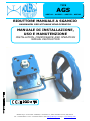
1
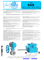
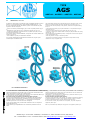
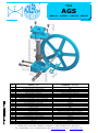
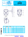
TYPE
AGS
AGS314 – AGS322 - AGS332 - AGS342
RIDUTTORE MANUALE A SGANCIO
HANDWHEEL DECLUTCHABLE GEAR OPERATOR
MANUALE DI INSTALLAZIONE,
USO E MANUTENZIONE
INSTALLATION, MAINTENANCE AND OPERATING
MANUAL INSTRUCTION
ADLER S.p.A. VALVOLE A SFERA, V.le Borletti 14, 20010 S.Stefano Ticino (MI) ITALY
Tel. +39 02974842.11 Fax. +39 0297271698 E-mail [email protected] http:// www.adlerspa.com
TYPE
AGS
AGS314 – AGS322 - AGS332 - AGS342
INDICE / INDEX
1.0
INTRODUZIONE / GENERAL
2.0
ISTRUZIONI PER LA SICUREZZA / WARNING
3.0
CONDIZIONI DI LAVORO E DATI TECNICI / WORKING CONDITIONS AND TECHNICAL DATA
4.0
CARATTERISTICHE FUNZIONALI E SENSO DI ROTAZIONE / OPERATIONG FUNCTION AND ROTATION SENSE
5.0
ISTRUZIONI DI INSTALLAZIONE DEL RIDUTTORE / INSTALLATION INSTRUCTION
6.0
ISTRUZIONI DI MANUTENZIONE (SMONTAGGIO E RIMONTAGGIO) / MAINTENANCE INSTRUCTION (DISASSEMBLY AND
ASSEMBLY)
7.0
STOCCAGGIO A MAGAZZINO / STORAGE
1.0
INTRODUZIONE / GENERAL
Il riduttore manuale a sgancio serie AGS è un modello a quarto di giro con
ingranaggio disinnestabile, utilizzabile su attuatori pneumatici a singolo e doppio
effetto.
Il riduttore AGS è concepito per un azionamento manuale della valvola, in caso
di guasto al sistema di attuazione automatica.
The gearbox model AGS is a quarter turn declutch gearbox, usable on pneumatic
actuators, both for single and for double acting.
The gearbox model AGS is intended and designed for manual operation of the
valve, in case of failure of the automatic actuator system.
Questo manuale di istruzioni contiene importanti informazioni relative
all’installazione, all’utilizzo, alla manutenzione e allo stoccaggio dei riduttori
manuali a sgancio ADLER AGS.
Leggere queste istruzioni attentamente e conservarle in caso di necessità.
È importante che l’assemblaggio e il disassemblaggio dei riduttori manuali
ADLER AGS sia effettuato solo da personale istruito.
This instruction manual contains important information regarding the installation,
operation, maintenance and storage for the ADLER AGS handwheel gearbox.
Please read these instructions carefully and save them for future reference.
It’s important that only properly trained personnel disassemble or assemble the
ADLER AGS handwheel gearboxes.
2.0
ISTRUZIONI PER LA SICUREZZA / WARNING
Per riduttori utilizzati in atmosfera potenzialmente esplosiva, assicurarsi che
le parti interne del riduttore non vengano mai in contatto con l’atmosfera
esterna.
L’utilizzo del riduttore al di fuori del range di temperatura previsto può
danneggiare componenti interni ed esterni.
L’utilizzo del riduttore in ambiente corrosivo senza adeguate protezioni può
danneggiare componenti interni ed esterni.
Prima dell’installazione, assicurarsi che il riduttore non venga sovraccaricato
durante l’uso: questo significa che il riduttore dovrà essere accoppiato a
valvola ed attuatore corretti: per accoppiamento, verificare i dati con la tabella
nell’ultima pagina di questo manuale.
Non smontare il riduttore quando è in movimento.
Prima dell’installazione su una valvola, assicurarsi che la rotazione di valvola
e riduttore sia concorde.
Se il riduttore è incorporato in un impianto, l’acquirente deve assicurarsi che
vengano rispettate le normative di sicurezza vigenti.
3.0
If the gearbox is installed in potentially explosive zone, make sure that the
internal parts of the gearbox cannot come in contact with the external
atmosphere.
Operating the gearbox above temperature limits will damage internal
and external components.
Operating the gearbox in corrosive environment with incorrect protection
may damage external and internal parts.
Before installation, make sure that the gearbox will not be overloaded
during the normal use. This means that the gearbox must be coupled with the
correct valve and actuator. For checking, see the table on the last pagefo this
manual, for the maximum allowable torque.
Do not disassemble the gearbox when in motion .
Before installing on a valve, make sure that the rotation of valve and
gearbox are the same.
If the gearbox is incorporated in a system or in a plant, the customer shall
ensure that the local safety regulations are observed.
CONDIZIONI DI LAVORO E DATI TECNICI / WORKING CONDITIONS AND TECHNICAL DATA
Temperatura operativa
Il range di temperatura operativa per riduttore ADLER AGS standard è -20°C <
T < +80°C
Corsa
La corsa per il riduttore ADLER AG standard è di 90° ± 5° con doppia
regolazione.
Lubrificazione
Tutte le parti in movimento del riduttore vengono consegnate lubrificate a vita.
Marcatura
Il tipo di riduttore, la dimensione, la temperatura di lavoro, il quadro e la
foratura ISO sono indicati sul riduttore stesso.
Connessioni
Foratura inferiore per accoppiamento valvola, secondo ISO 5211/DIN 3337.
Foratura superiore per accoppiamento attuatore, secondo ISO 5211/DIN 3337.
Manovre
Ogni singolo riduttore è garantito per un numero di 20000 manovre. Tale
garanzia è subordinata ad un uso corretto (vedere condizioni di esercizio).
Operating temperature
The temperature range for the Standard gearbox ADLER AGS is -20°C < T <
+80°C.
Stroke
The stroke for ADLER AGS standard gearbox is 90° ± 5° with double
adjustment.
Lubrification
The gearbox is factory life lubrificated in normal working conditions.
Gearbox Marking
The gearbox type, size, operating temperature, the square connection, the ISO
drilling are marked on the gearbox.
Connections
Bottom drilling to match valve is in accordance with ISO 5211/DIN 3337.
Top drilling to match actuator is in accordance with ISO 5211/DIN 3337.
Movements
Each gearbox is guaranteed for a 20000 movements. Such warranty is subject
to a proper use (see the specifications).
ADLER S.p.A. VALVOLE A SFERA, V.le Borletti 14, 20010 S.Stefano Ticino (MI) ITALY
Tel. +39 02974842.11 Fax. +39 0297271698 E-mail [email protected] http:// www.adlerspa.com
TYPE
AGS
AGS314 – AGS322 - AGS332 - AGS342
4.0
CARATTERISTICHE FUNZIONALI E SENSO DI ROTAZIONE / OPERATING FUNCTION AND ROTATION SENSE
Il riduttore ADLER AGS è stato progettato per il funzionamento a 90°. Il
riduttore ha un angolo di rotazione totale di 100°: 90° più 5° dopo l’apertura e
meno 5° dopo la chiusura.
Tutti i riduttori sono progettati in modo tale da avere una rotazione oraria per la
chiusura e antioraria per l’apertura.
5.0
ADLER AGS gearbox is designed for 90° operations. The gearbox design allows
an angle of total rotation of 100°: 90° plus 5 degrees more than the valve
opening and 5° more then the valve closing.
All the gearboxes are designed in order to have a clockwise rotation for the valve
closing and a counter-clockwise rotation for the valve opening.
ISTRUZIONI DI INSTALLAZIONE DEL RIDUTTORE / GEARBOX INSTALLATION INSTRUCTION
Il riduttore a sgancio ADLER AGS è un apparecchio per la movimentazione di
valvole, il cui scopo è movimentare la valvola in caso di guasto del sistema di
attuazione.
In particolare il riduttore ADLER AGS standard opera su un angolo di 90°,
rendendo possibile apertura e chiusura di valvole a ¼ di giro, principalmente
valvole a sfera.
The ADLER AGS gearbox is a mechanical and manual device for the remote
operation of industrial valves, and is designed to operate the valve in case of
failure in the actuator system.
In particular the standard ADLER AGS declutch gearbox operates through 90°,
allowing the opening and closing of ¼ turn valves, notably ball valves.
Tutte le informazioni tecniche necessarie per l’installazione corretta e sicura del
riduttore sulla valvola (modello, connessioni, dimensioni, coppia in uscita,
regolazione corsa, temperatura di utilizzo) sono chiaramente indicate sul riduttore
o sulla scheda tecnica.
Leggere attentamente le informazioni tecniche seguenti prima di procedere con
l’installazione del riduttore.
All the necessary technical information for a proper installation of the gearbox
on the valve (model, connections, dimensions, output torque, stroke
adjustment and operating temperature) are stated clearly on the gearbox or in
the technical data sheets.
Please read this technical information carefully, before proceeding with the
gearbox installation.
5.1 Il riduttore è normalmente fornito in condizione di chiusura
5.2 È raccomandato il montaggio del volante sull’albero di manovra prima di
assemblare il riduttore sulla valvola
5.3 Verificare la corrispondenza delle forature ISO tra riduttore e valvola
5.4
5.5
5.6
5.7
5.1
Assicurarsi che la valvola sia in posizione di chiusura
Montare il riduttore in direzione perpendicolare alla valvola (vedi fig. 1)
Serrare opportunamente le viti di collegamento.
Ora il riduttore è pronto per la regolazione
5.1 The gearbox is standard delivered in the closed position
5.2 It is recommended to mount the handwheel on the input shaft before
assembling the gearbox on the valve
5.3 Check the correspondence between the ISO drilling on the valve and on the
gearbox
5.4 Make sure that the valve is in closed position.
5.5 Mount the gearbox in a direction perpendicular to the valve (see fig.1)
5.6 Fasten properly the gearbox to the valve.
5.7 Now the assembly is ready for adjustment.
REGOLAZIONE DELLE VITI FINECORSA / ADJUSTMENT OF THE STOPSCREWS
Con il riduttore montato sulla valvola:
▪ Se è collegato un attuatore pneumatico, assicurarsi che lo stesso attuatore sia
depressurizzato;
▪ Mettere il riduttore in modalità manuale, abbassando la leva di manovra (21),
secondo le procedure descritte al punto 5.2;
▪ Mettere la valvola in posizione di completa chiusura, girando il volante di
manovra (22) in senso orario: se la posizione di completa chiusura non può
essere raggiunta, allentare la vite di regolazione di chiusura (12) (vedi fig. 2).
Continuare a girare il volantino finché la valvola non sia completamente chiusa.
▪ Avvitare quindi a mano la vite di regolazione (12) fino a che va a battuta
sull’ingranaggio interno. Quindi bloccarla con il controdado (11).
▪ Aprire la valvola girando il volantino (22) in senso antiorario: se la posizione di
completa apertura non può essere raggiunta, allentare la vite di regolazione di
apertura (vedi fig. 2). Continuare a girare il volantino finché la valvola non sia
completamente aperta.
▪ Avvitare quindi a mano la vite di regolazione (12) fino a che va a battuta
sull’ingranaggio interno. Quindi bloccarla con il controdado (11).
▪ Chiudere completamente la valvola con il volantino.
▪ Mettere il riduttore in modalità automatica, sollevando la leva di manovra (21),
secondo le procedure descritte al punto 5.2;
▪ La regolazione è ora completa. Il riduttore è pronto al funzionamento sia
manuale che automatico.
FIG. 1 GEARBOX MOUNTING
With the gearbox mounted on top of the valve:
▪ In case of pneumatic actuator, be sure that the actuator is not pressurised;
▪ Put the gearbox in the manual-mode, by lowering the control handle (21),
following the procedures described at point 5.2;
▪ Put the valve into full closed position by turning the handwheel (22) clockwise:
if the fully closed position cannot be achieved, loosen the stop screw-close (12)
(see fig. 2).
Continue in turning the handwheel until the valve is fully closed.
▪ Turn the screw (12) back into the gearbox until is blocked (hand tight). Secure
the stop screw-close with the counter nut (11).
▪ Open the valve by turning the handwheel (22) counter-clockwise: if the fully
open position cannot be achieved, loosen the stop screw-open (see fig. 2).
Continue in turning the handwheel until the valve is fully open.
▪ Turn the screw (12) back into the gearbox until is blocked (hand tight). Secure
the stop screw-close with the counter nut (11).
▪ Close the valve completely with the handwheel;
▪ Put the gearbox in autol-mode, by rising the control handle (21), following the
procedures described at point 5.2;
▪ The adjustment now is complete. The gearbox is ready for manual or automatic
operations.
FIG. 2 ADJUSTMENT OF THE STOPSCREWS
ADLER S.p.A. VALVOLE A SFERA, V.le Borletti 14, 20010 S.Stefano Ticino (MI) ITALY
Tel. +39 02974842.11 Fax. +39 0297271698 E-mail [email protected] http:// www.adlerspa.com
TYPE
AGS
AGS314 – AGS322 - AGS332 - AGS342
5.2
OPERATIVITÁ / OPERATING
Il riduttore a sgancio AGS è normalmente fornito in modalità automatica: leva di
manovra (21) in posizione AUTO e valvola azionata dall’attuatore (fig. 3-1).
Per avere l’operatività manuale del riduttore, operare come descritto nei punti
seguenti e osservare la figura 3:
The declutchable gearbox AGS is standard delivered in automatic mode: control
handle (21) in AUTO position and valve operated by the actuator (fig. 3-1).
To achieve the manual operating of the gearbox, follow the next points looking
the fig.3:
▪ Tirare verso l’alto il pin di bloccaggio (24) e tenerlo in questa posizione (fig. 32)
▪ Abbassare la leva di manovra (21) e rilasciare il pomello (24) (fig. 3-3)
▪ Continuare ad abbassare la leva di manovra (21) finchè il pin (24) non va in
posizione di sicurezza (fig. 3-4)
Tra posizione AUTO e posizione MANUAL, corrisponde una rotazione della leva di
manovra (21) di 90°
▪ Ora il riduttore è pronto per l’azionamento manuale
▪ Pull outwards the locking pin (24) and maintain it in this position during the
operation (fig. 3-2)
▪ Lower the control handle (21) and release the pin (24) (fig. 3-3).
▪ Continue to lowering the control handle until the pin (24) falls back into locking
position (fig. 3-4)
From AUTO position and MANUAL position, corresponds a rotation of 90 degrees
of the control handle (21).
▪ Now the gearbox is ready for manual operation.
Per ritornare all’azionamento automatico del riduttore AGS, seguire i passi
illustrati sopra in modalità inversa.
To return to the automatic operation of the gearbox AGS, follow the step
illustrated on top in a opposite way.
FIG. 3 GEARBOX OPERATIVITY
6.0 ISTRUZIONI DI MANUTENZIONE (SMONTAGGIO E RIMONTAGGIO) / MAINTENANCE INSTRUCTION (DISASSEMBLY AND ASSEMBLY)
Tramite le informazioni sotto riportate, Adler S.p.A fornisce all’utilizzatore finale
tutte le informazioni necessarie per la manutenzione.
La manutenzione dei riduttori Adler AGS è permessa solo al personale Adler S.p.A
o a personale che sia stato opportunamente istruito.
Ogni inosservanza comporterà il decadimento della garanzia!
Per un buon funzionamento del riduttore e per garantirne una lunga durata, si
consiglia un piano di manutenzione da effettuare a circa 5.000 manovre per
verificare lo stato di usura delle tenute (*) e la presenza di una adeguata
quantità di grasso tra la vite senza fine e la cremagliera.
In caso di usura delle tenute procedere alla sostituzione solo con componenti
forniti dall’ Adler S.p.A.,
L’Adler declina ogni responsabilità in caso di utilizzo di particolari non da Lei
forniti.
With the information given below, Adler S.p.A provides the end user with all the
required information for the maintenance.
Maintenance of the AGS gearbox is allowed only to personnel of Adler S.p.A or
to personnel which are properly instructed.
By contraventions the guarantees expires!
To ensure a long-lasting use of the gearbox, we suggest a maintenance checking
at 5.000 movements, in order to verify the state of wear of seals (*) and the
presence of adequate amount of grease between gear and worm.
In case of wear of seals, they will have to be replaced, only with component
supplied by Adler S.p.A.
Adler S.p.A. disclaims any liability for using parts not supplied by Adler S.p.A..
ADLER S.p.A. VALVOLE A SFERA, V.le Borletti 14, 20010 S.Stefano Ticino (MI) ITALY
Tel. +39 02974842.11 Fax. +39 0297271698 E-mail [email protected] http:// www.adlerspa.com
TYPE
AGS
AGS314 – AGS322 - AGS332 - AGS342
N°
PARTE / ITEM
MATERIALE / MATERIAL
1
2
3
4
5
6
7
8
9
10
11
12
13
14
15
16
17
18
19
20
21
22
23
24
25
Coperchio / Cover
O-Ring Ingranaggio / Wheel O-Ring
Anello elastico / Clip spring
Giunto / Joint
Spina cilindrica / Dowell pin
Chiavetta / Key
Albero / Shaft
Ingranaggio / Gear
Guarnizione viti Regolazione / Stop screw Gasket
Tappo viti di Regolazione / Nut protection Sheath
Dado di Regolazione + Rondella / Counter Nut + Washer
Vite di Regolazione / Stop screw
Corpo riduttore / Housing
Spina cilindrica / Dowell pin
O-Ring / O-Ring
O-Ring / O-Ring
Vite senza fine / Worm
Boccola / Bushing
Albero eccentrico / Eccentric Rack
Grano / Screw
Leva di manovra / Control Handle
Volante di manovra / Handwheel
Guarnizione corpo–laterale / body–end Gasket
Pin / Pin
Vite + rondella / Bolt + washer
Alluminio verniciato / Painted Aluminium
NBR
Acciaio al carbonio / Black steel
C45
Acciaio al carbonio / Black steel
C45
AISI 304
Ghisa / Ductile iron
NBR
NBR
Acciaio zincato / Galvanized steel
AISI304
Alluminio verniciato / Painted Aluminium
Acciaio al carbonio / Black steel
NBR
NBR
C45
Materiale sinterizzato / Powder metallurgy
C45
AISI304
AISI304
Acciaio al carbonio verniciato / Painted carbon steel
NBR
AISI 304
AISI 304
ADLER S.p.A. VALVOLE A SFERA, V.le Borletti 14, 20010 S.Stefano Ticino (MI) ITALY
Tel. +39 02974842.11 Fax. +39 0297271698 E-mail [email protected] http:// www.adlerspa.com
TYPE
AGS
AGS314 – AGS322 - AGS332 - AGS342
6.1
SMONTAGGIO/DISASSEMBLY
Verificare che il riduttore sia in posizione di completa apertura o chiusura
prima di rimuoverlo dalla valvola e dall’attuatore per non compromettere il
funzionamento della stessa.
Quando è richiesto lo smontaggio del riduttore per manutenzione, prima di
tutto scollegare meccanicamente il riduttore dalla valvola e dall’attuatore.
Verificare che il riduttore non sia collegato ad altri apparecchi (in caso
scollegarli completamente).
Before performing any disassembling of the gearbox from the valve and from
the actuator, verify that it is in a position of complete opening or closing: this
is mandatory to avoid any compromising to the valve efficiency.
When disassembly of gearbox is required for maintenance, firstly remove the
gearbox from the valve and from the actuator.
Check that the gearbox is not connected to other devices (if connected,
disassemble them completely).
Rimozione viti di regolazione
Rimuovere i tappi di protezione (10), svitare le 2 viti di regolazione (12) e i
relativi dadi (11), sfilare le guarnizioni (9)
Adjusting screw removal
Remove the bolt caps (10), then the adjusting screws (12) and nuts (11) and
the gaskets (9)
Rimozione coperchio
Svitare le viti e le rondelle (25), rimuovere il coperchio (1) facendo attenzione a
non danneggiare la guarnizione di tenuta (23).
Coverplate removal
Remove the screws and the washer (25), remove the cover (1) paying
attention in not damaging the coverplate gasket (23).
Rimozione dell’ingranaggio
Asicurarsi che il riduttore sia in posizione ‘auto’ (fig. 1-1).
Rimuovere il giunto (4)
Estrarre l’ingranaggio (8) facendo pressione dalla parte inferiore del corpo,
facendo attenzione a non rovinare gli O-Ring di tenuta (2).
Gearl removal
Put the gearbox in ‘auto’ position (fig. 1-1)
Remove the joint (4)
Extract the gear (8) by applying a pressure to the surface on the bottom
side, paying attention in not damaging the sealing O-Rings (2).
Rimozione vite senza fine
Mantenere il corpo (13) in una morsa, estrarre la spina (5) e rimuovere il
volante di manovra (22).
Rimuovere la spina (14).
Rimuovere l’albero (7) facendo attenzione a non danneggiare le tenute (15).
Rimuovere la vite senza fine (17).
Rimozione alberi accentrici
Svitare i grani (20)
Sfilare gli alberi eccentrici (19) verso l’interno del corpo (13)
La leva di manovra (21) verrà di conseguenza staccata dal corpo (13)
QUANDO TUTTI I COMPONENTI SONO SMONTATI, VERIFICARE LE SUPERFICI DI
CONTATTO E DI USURA PER RILEVARE EVENTUALI ECCESSIVI CONSUMI O
DANNEGGIAMENTI.
ASSICURARSI CHE TUTTE LE PARTI SIANO ANCORA ENTRO LE TOLLERANZE
PREVISTE DALLA FABBRICA PRIMA DEL RIASSEMBLAGGIO.
6.2
Worm removal
Positioning the gearbox housing (13) in a clamp, pull out the dowell pin (5)
and remove the hand-wheel (22).
Remove the dowell pin (14).
Remove the shaft (7) paying attention in not damaging the sealing (15).
Remove the worm (17).
Eccentric rack removal
Unscrew the screws (20)
Slip off the eccentric racks (19) inwards the housing (13)
The controll handle (21) will be removed from the housing (13)
WHEN ALL COMPONENTS ARE DISASSEMBLED, VERIFY ALL THE CONTACT AND
WEAR SURFACE TO CHECK IF EVENTUALLY THERE ARE ECCESSIVE WEAR OR
DAMAGES.
ENSURE THAT ALL COMPONENTS RESPECT THE EXPECTED TOLERANCES BEFORE
RE-ASSEMBLING.
MONTAGGIO/ASSEMBLY
Assicurarsi che tutte le parti di movimento siano lubrificate abbondantemente
con grasso al litio.
Make sure that all the moving parts are copiously lubrificated with lithium
grease.
Assemblaggio alberi accentrici
Posizionare la leva di manovra (21) vicino al corpo (13)
Infilare gli eccentrici (19) nei corrispondenti fori sul corpo (13) e sulla leva di
manovra (21)
Avvitare i grani (20)
Eccentric rack assembly
Approach the control handle (21) to the housing (13)
Slip on the eccentric racks (19) into the coresponding holes on the housing
(13) and on the controll handle (21)
Screw the screws (20)
Assemblaggio vite senza fine
Posizionare la vite senza fine (17) in asse e tra i due eccentrici (19), inserire
l’albero (7) e bloccarlo con la spina (14) facendo attenzione a non danneggiare
le tenute (15).
Mettere il volantino di manovra (22) sul l’albero (7) e inserire la spina (5).
Worm assembly
Put the worm (17) between and axially the two eccentric racks (19), insert the
input shaft (7) and lock it with the dowell pin (14) paying attention in not
damaging the sealings (15).
Put the Handwheel (22) on the shaft (7) and insert the dowell pin (5).
Assemblaggio ingranaggio
Montare gli O-Ring (2) nelle apposite sedi dell’ingranaggio (8)
Inserire l’ingranaggio nella apposita sede e premere verso il basso fino a
battuta facendo attenzione a non rovinare gli O-Ring.
Wheel assembly
Assemble the O-Rings (2) into the proper grooves on the gear (8).
Insert the gear into the proper seat on the gearbox housing and press down
until its right position, paying attention in not damaging the O-Rings.
Assemblaggio del coperchio
Posizionare la guarnizione (23)
Appoggiare il coperchio (1) e inserire le viti e rondelle (25) (prima di inserire le
viti assicurarsi che i fori di coperchio e guarnizione siano allineati)
Serrare le viti a fondo.
Cover assembly
Position the cover plate gasket (23)
Position the cover (1) and insert the screws and washers (25) (check that the
holes on the gasket and on the cover are aligned).
Tighten the screws.
Assemblaggio viti di regolazione e regolazione corsa
• Inserire nei fori le guarnizioni (9), le viti di regolazione (12) e i dadi (11).
Avvitare le viti (12) sul corpo.
Posizionare il tappo della vite di regolazione (10).
7.0
Assembly screws and adjusting stroke
Insert in the proper holes the gaskets (9), the stroke adjustment screws (12)
and the nuts (11).
Tighten the screws (12) on the body.
Position the screw cap (10).
STOCCAGGIO A MAGAZZINO / STORAGE
Se per il riduttore non è previsto un uso immediato, prevedere le seguenti
precauzioni:
Immagazzinare in un ambiente asciutto e a temperatura ambiente.
Non rimuovere particolari.
Eseguire una serie di manovre complete ogni 90-100 giorni per evitare la
deformazione permanente delle tenute.
If the gearbox is not for immediate use, must be taken the following precautions:
Store in a dry environment at ambient temperature.
Do not remove any detail.
Perform a series of complete turns every 90-100 days to avoid permanent
deformation of the seals
ADLER S.p.A. VALVOLE A SFERA, V.le Borletti 14, 20010 S.Stefano Ticino (MI) ITALY
Tel. +39 02974842.11 Fax. +39 0297271698 E-mail [email protected] http:// www.adlerspa.com
TYPE
AGS
AGS314 – AGS322 - AGS332 - AGS342
MODELLO
TYPE
COPPIA DI
INGRESSO
INPUT TORQUE
[Nm]
COPPIA DI
USCITA
OUTPUT TORQUE
[Nm]
B
C
E
F
G
H
L
M
ØS
PESO
WEIGHT
[kg]
AGS-314
31
300
125
110
44.2
54
90
100
143
104
200
2.7
AGS-322
65
810
185
160
65
70
140
124
190
140
400
6.8
AGS-332
131
1310
225
200
85
78
185
162
325
180
600
13.5
AGS-342
147
2800
268
243
104.5
105
230
181
395
214
800
25.8
ADLER S.p.A. VALVOLE A SFERA, V.le Borletti 14, 20010 S.Stefano Ticino (MI) ITALY
Tel. +39 02974842.11 Fax. +39 0297271698 E-mail [email protected] http:// www.adlerspa.com