1
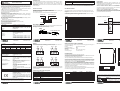
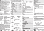
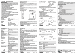
Z-8TC
CONVERTITORE PER TERMOCOPPIE
CON ISOLAMENTO A SEI PUNTI
Descrizione Generale
Lo strumento Z-8TC è un convertitore digitale per termocoppie, con otto canali di misura,
isolati dall’alimentazione e dalla linea di comunicazione seriale fino a 1.5 kV. Lo stesso
isolamento pari a 1.5 kV è previsto tra canali facenti capo a gruppi diversi di morsetti. Il
modulo è dunque caratterizzato da un isolamento complessivo a sei punti. In aggiunta
esso è caratterizzato da:
Cablaggio facilitato dell'alimentazione e del bus seriale per mezzo del bus alloggiato
nella guida DIN.
Configurabilità della comunicazione tramite DIP-switch o via software.
Comunicazione seriale RS485 con protocollo MODBUS -RTU, massimo 32 nodi.
Protezione contro scariche ESD fino a 4 kV.
Elevata velocità di acquisizione.
Misura di termocoppie: J, K, E, N, S, R, B, T.
Misura degli ingressi disponibile nei seguenti formati: rappresentazione floating-point,
floating-point inversa, virgola fissa a 16 bit, in decimi di grado con segno per la
temperatura, decine di mV per la tensione.
Canali attivabili singolarmente.
Valore programmabile in caso di fault o congelamento ultima lettura .
Per ciascuna coppia di ingressi relativi allo stesso gruppo di morsetti sono previste le
seguenti impostazioni comuni:
Misura impostabile in temperatura o mV.
Filtro programmabile a otto livelli per la stabilizzazione della lettura.
Reiezione programmabile a 50 Hz o 60 Hz.
Tre diverse velocità di acquisizione selezionabili (due a 14 bit, una a 15 bit).
Compensazione giunto freddo.
Norme di installazione
10..40 Vdc o 19..28 Vac (50..60 Hz).
max 0,6 W.
Porte di Comunicazione Seriale : -RS485, 1200..115200 Baud.
-RS232, 2400 Baud, Indirizzo:01, Parità: NO, Dati: 8
bit; Stop bit: 1.
MODBUS-RTU.
Protocollo :
Ingressi
Termocoppia di tipo: J, K, E, N, S, R, B, T.
Ingresso :
EN60584-1 (ITS-90).
Tabelle :
Dipendente dal tipo di termocoppia (vedere Tabella
Range di temperatura :
Range Termocoppie).
-10,1..81,4 mV.
Span mV:
Impedenza :
10 MW.
Errore complessivo :
ADC 14 bit e Reiez. 50 Hz: "(0,040 % + 13 mV).
ADC 15 bit e Reiez. 50 Hz: "(0,035 % + 10 mV).
ADC 14 bit e Reiez. 60 Hz: "(0,045 % + 16 mV).
ADC 15 bit e Reiez. 60 Hz: "(0,040 % + 12 mV).
MI001230-I
Corrente Test :
(1)
CMRR :
(1) (2)
DMRR
:
Collegamenti Elettrici
IMPOSTAZIONE DEI DIP-SWITCH
PORTA SERIALE RS485 E ALIMENTAZIONE
I collegamenti elettrici relativi al bus RS485 e all’alimentazione sono disponibili
esclusivamente utilizzando il bus per guida DIN Seneca.
I collegamenti del connettore del bus per guida DIN sono visibili nella figura seguente.
Power Supply AC-
RS485 A
RANGE TERMOCOPPIE
Range
Errore
Errore
Range
TIPO TC
Ammesso Linearizzazione
Ammesso Linearizzazione
S
J
-50..1768 °C
-210..1200 °C
0,05 °C
0,02 °C
-200..1372 °C
R
-50..1768 °C
K
0,05 °C
0,02 °C
-200..1000 °C
B
E
0,02 °C
0,03 °C
250..1820 °C (3)
N
-200..400 °C
-200..1300 °C
T
0,04 °C
0,04 °C
Altre Caratteristiche
Impostabile a 14 o 15 bit.
ADC :
< 100 ppm/K.
Deriva Termica :
Impostabile a 50 Hz o a 60 Hz.
Reiezione ai disturbi :
<1 °C.
Errore Giunto Freddo :
Tensione di isolamento :
1500 Vac tra porte di: alimentazione, comunicazione e
ingresso.
1500 Vac tra canali relativi a gruppi di morsetti diversi.
Grado di protezione :
IP20.
Condizioni ambientali :
Temperatura -10..+65 °C, Salvataggio parametri in
EEPROM garantito nel range: 0..50 °C.
Umidità 30..90 % non condensante.
Altitudine 2000 slm.
Temp. Stoccaggio :
-20..+85 °C.
Segnalazioni LED :
Alimentazione, Fail, Comunicazione RS485.
Connessioni :
-Morsetti a vite estraibili a 4 vie, max 1.5 mm2, passo
3.5 mm.
-Connettore posteriore IDC10 per barra DIN.
-Jack frontale stereofonico 3.5 mm per connessione
RS232 (COM).
PBT, colore nero.
100 x 112 x 17,5 mm, 140 g.
EN61000-6-4/2002-10 (emissione elettromagnetica,
ambiente industriale).
EN61000-6-2/2006-10 (immunità elettromagnetica,
ambiente industriale).
EN61010-1/2001 (sicurezza).
Tutti i circuiti devono essere isolati con doppio
isolamento dai circuiti sotto tensione pericolosa. Il
trasformatore di alimentazione deve essere a norma
EN60742: “Trasformatori di isolamento e
trasformatori di sicurezza”.
(1)
I valori sono validi alla frequenza di reiezione impostata, con il filtro inserito.
Per valori del disturbo tali che il picco del segnale d’ingresso non ne superi l’accettabilità.
(3)
Fino a 250 °C si assume un valore di temperatura nulla.
(2)
MI001230-I
ITALIANO - 2/16
Configurazione di Fabbrica
Lo strumento esce dalla fabbrica configurato con tutti i DIP-switch in posizione 0. La
posizione dei dip-switch definisce i parametri di comunicazione del modulo: indirizzo e
velocità.
VELOCITÀ
SW1 1 2
1
RS485 B
IDC10
DB9-F
6
1
GND
Tx
Jack stereo 3.5 mm
Rx
GND
MI001230-I
Tx
Rx
TC 4
TC 3
9
TC 6
+
+
4
-
5
6
7
8
TC 7
-
-
-
13 14 15 16
10 11 12
Le coppie di canali facenti parte dello stesso gruppo di morsetti hanno il terminale di
massa internamente connesso e non sono isolati tra loro. È invece garantito un
isolamento pari a 1,5 kV tra canali relativi a gruppi di morsetti diversi.
Indicazioni tramite LED sul frontale
TX
COM
S
Z-8TC
La configurazione di default è la seguente: Indirizzo 1, 38400, no parity, 1 bit di stop.
ITALIANO - 5/16
MI001230-I
ITALIANO - 7/16
Dimensioni e Ingombri
La configurazione di default, valida per ciascuna coppia di canali relativi allo stesso gruppo
di morsetti è la seguente :
Entrambi i canali abilitati
Abilitazione :
°C
Dato restituito :
Compensazione giunto freddo : Attiva
50 Hz
Reizione :
ADC 15 bit con filtro in media
ADC / Filtro :
J per entrambi i canali.
Tipo Termocoppia :
Per ogni gruppo di canali è possibile impostare le modalità di filtratura. Il filtro è composto
da due filtri passa basso indipendenti:
- Filtro FIR, in media mobile in grado di aumentare la reiezione ai disturbi alla frequenza di
rete e di ridurre il rumore di misura.
- Filtro IIR esponenziale, con costante di tempo programmabile, in grado di smorzare le
fluttuazioni.
Se viene rilevata una variazione dell’ingresso superiore alla soglia S, entrambi i filtri
vengono forzati ad adeguarsi rapidamente al nuovo valore, per intervenire solo
successivamente a stabilizzarlo. Il valore della soglia è fisso in tensione e pari a circa 0,75
mV. Il filtro viene impostato tramite i tre bit meno significativi dei registri MODBUS
40054..57 (fare riferimento alla sezione REGISTRI MODBUS).
Di seguito si riporta una tabella con tutti i tipi di filtraggio impostabili. Per ciascuno di questi
viene inoltre riportato il tempo di propagazione (90%), cioè il tempo massimo che
trascorre tra la variazione a gradino dell’ingresso e la variazione del numero che la
rappresenta nel registro Modbus, compreso il tempo di interrogazione del singolo registro
(a 115 kbaud). I tempi riportati in tabella valgono se sono rispettate entrambe le seguenti
condizioni :
- Reiezione a 50 Hz. Se a 60 Hz dividere i tempi riportati per 1,2.
- Abilitazione di una sola delle due termocoppie del gruppo. Se entrambe le termocoppie
sono abilitate i tempi con buona approssimazione raddoppiano.
SET
000
001
010 (5)
011
100
101
110
111
LED ERR (GIALLO) Significato
Acceso
Guasto: alimentazione insufficiente, canale guasto,TC guasta,
errore di comunicazione interna
(segnalati se il canale
corrispondente è attivato).
Significato
Indica la ricezione di dati sulla porta di comunicazione RS485.
MI001230-I
RX
9 10 11 12
MI001230-I
LED PWR (VERDE) Significato
Acceso
Indica la presenza dell’alimentazione.
LED RX (ROSSO)
Acceso
Trasmissione RS485
Ricezione RS485
IMPOSTAZIONE FILTRO
TC 8
+
-
3
-
+
+
TC 5
+
2
+
+
1
-
Presenza alimentazione
13 14 15 16
IMPOSTAZIONE DI DEFAULT CANALI INGRESSO
Il modulo accetta in ingresso termocoppie di tipo: J, K, E, N, S, R, B, T.
Per i collegamenti elettrici si raccomanda l’utilizzo di cavo schermato.
-
ERR PWR
TERMINAZIONE RS485
SW1 10
Nessuna Terminazione di linea
Terminatore di linea inserito
ITALIANO - 3/16
INGRESSI
TC 2
Errore
NON USATO
SW1 9 Non usato
Lasciare in posizione OFF.
(4)
TC 1
1 2 3 4
Parametri di comunicazione da EEPROM (4)
Indirizzo fisso 01
Indirizzo fisso 02
Indirizzo fisso 03
Indirizzo fisso 04
X X X X X X Indirizzo fisso, come da rappresentazione binaria
Indirizzo fisso 63
Il cavo di connessione DB9 Jack stereo 3.5 mm può essere assemblato come indicato
nella figura seguente, oppure acquistato come accessorio. Si evidenzia inoltre che il GND
della RS232 è il medesimo della RS485.
5
La programmazione del modulo può essere effettuata anche attraverso il connettore
frontale (COM), facendo attenzione ad impostare i seguenti parametri per il collegamento:
Indirizzo=001, Velocità=2400 Baud, PARITA'=nessuna, STOP BIT = 1.
La porta di comunicazione COM si comporta esattamente come quella del bus RS485
eccetto che per i parametri di comunicazione come già descritto. Inoltre ha priorità sulla
porta RS485 e viene chiusa dopo 3 s di inattività.
5 6 7 8
INDIRIZZO
SW1 3 4 5 6 7 8
PORTA SERIALE RS232
9
Per i tool di programmazione e/o configurazione del prodotto consultare il sito
www.seneca.it.
Durante la prima programmazione è possibile utilizzare le impostazioni di default da
EEPROM (SW1.3..8 in posizione OFF) che sono all'origine programmate come segue:
Indirizzo=001, VELOCITA'=38400 Baud, PARITA'=nessuna, NUMERO BIT=8, STOP
BIT=1.
Pannello Frontale e Posizione Led
9600 Baud
19200 Baud
38400 Baud
57600 Baud
TIPO TC
Contenitore :
Dimensioni, Peso :
Normative :
Per informazioni dettagliate sull’interfaccia seriale RS485 fare riferimento alla
documentazione presente nel sito www.seneca.it, nella sezione Prodotti/Serie ZPC/MODBUS TUTORIAL.
Programmazione
In tutte le tabelle seguenti l’indicazione corrisponde a DIP-switch in 1 (ON);
nessuna indicazione corrisponde a DIP-switch in 0 (OFF)
Power Supply AC+
RS485 GND
ITALIANO - 1/16
<50 nA.
>155 dB (porta in prova verso tutte le altre a GND).
>60 dB.
Significato
Indica la trasmissione di dati sulla porta di comunicazione RS485.
Interfaccia Seriale
Caratteristiche Tecniche
Alimentazione :
Consumo :
LED TX (ROSSO)
Acceso
Il modulo è progettato per essere montato su guida DIN 46277, in posizione verticale.
Per un funzionamento ed una durata ottimale, è necessario assicurare una adeguata
ventilazione al/ai moduli, evitando di posizionare canaline o altri oggetti che occludano le
feritoie di ventilazione.
Evitare il montaggio dei moduli sopra ad apparecchiature che generano calore; è
consigliabile il montaggio nella parte bassa del quadro.
ITALIANO - 4/16
112 mm
I
(5)
SAMPLING
Bit ADC
Hz
14
48
14
20
15
11
15
11
15
11
15
11
15
11
15
11
FILTRO
TIPO
Non presente
Media
Media
Media + exp
Media + exp
Media + exp
Media + exp
Media + exp
TEMPO PROP. 90%
<S
>S
45 ms
45 ms
236 ms
103 ms
405 ms
179 ms
1s
179 ms
3s
179 ms
8s
179 ms
24 s
179 ms
72 s
179 ms
17,5 mm
100 mm
Questo documento è di proprietà SENECA srl. La duplicazione e la riproduzione sono vietate, se non
autorizzate. Il contenuto della presente documentazione corrisponde ai prodotti e alle tecnologie
descritte. I dati riportati potranno essere modificati o integrati per esigenze tecniche e/o commerciali. Il
contenuto della presente
R
THE INTERNATIONAL CERTIFICATION NETWORK
ISO9001-2000
Valore di default.
MI001230-I
ITALIANO - 6/16
SENECA s.r.l.
Via Germania, 34 - 35127 - Z.I. CAMIN - PADOVA - ITALY
Tel. +39.049.8705355 - 8705359 - Fax +39.049.8706287
e-mail: [email protected] - www.seneca.it
MI001230-I
ITALIANO - 8/16
REGISTRI MODBUS
CHAN8_DEC
Il modulo Z-8TC dispone di registri MODBUS a 16 bits (words) accessibili tramite
comunicazione seriale RS485 o RS232. Nei prossimi paragrafi si descrivono i comandi
MODBUS supportati e le funzionalità esprimibili dai vari registri.
Bit [15:0]
CHAN1_FLOAT_H
Comandi MODBUS supportati
Funzione
Codice
Descrizione
Lettura di registri a word fino a 32 per volta
03 (*) Read Holding Registers
Lettura di registri a word fino a 32 per volta
04 (*) Read Input Registers
Scrittura di un registro a word
Write Single Register
06
Scrittura di registri a word fino a 32 per volta
Write Multiple Registers
16
(*) Le due funzioni hanno lo stesso effetto
Bit [15:0]
CHAN1_FLOAT_L
Bit [15:0]
CHAN2_FLOAT_H
Holding Registers
Bit [15:0]
I registri Holding Registers a 16 bits hanno la seguente struttura :
Bit più
Bit meno
Indice Bit
significativo
significativo
CHAN2_FLOAT_L
Bit [15:0]
15 14 13 12 11 10 9 8 7 6 5 4 3 2 1 0
CHAN3_FLOAT_H
Word (16 bits): Registro MODBUS
La notazione Bit [x:y] riportata in tabella indica tutti i bit dal x a y. Ad esempio Bit [2:1] indica
il bit 2 e il bit 1, e serve ad illustrare il significato delle varie combinazioni congiunte di valori
dei due bit. Da ricordare che sui seguenti registri possono essere eseguite le funzioni
MODBUS 3, 4, 6 e 16, di lettura e scrittura singola e multipla.
I valori contrassegnati con il simbolo * sono quelli di default.
REGISTRO
MACHINE ID
STATUS_INP
Bit 15
Bit 14
IND. R/W
Descrizione
40001 R
La parte alta del registro contiene l'ID del
modulo ( 24 ) Bit [15:8]
La parte bassa la revisione firmware Bit [7:0]
40002 R
Stato dei canali d’ingresso
1: Guasto ai canali 1 e 2.
1: Guasto ai canali 7 e 8.
Bit 11
1: Guasto alla TC collegata al canale 1.
MI001230-I
CHAN2_DEC
Bit [15:0]
CHAN3_DEC
Bit [15:0]
CHAN4_DEC
Bit [15:0]
CHAN5_DEC
Bit [15:0]
CHAN6_DEC
Bit [15:0]
CHAN7_DEC
Bit [15:0]
CHAN4_FLOAT_H
Bit [15:0]
CHAN4_FLOAT_L
CHAN5_FLOAT_H
Bit 12
Bit [15:0]
Bit [15:0]
Bit [15:0]
1: Guasto ai canali 5 e 6.
Bit 0
CHAN1_DEC
CHAN3_FLOAT_L
1: Guasto ai canali 3 e 4.
Bit 13
Bit 10
Bit 9
Bit 8
Bit 7
Bit 6
Bit 5
Bit 4
Bit 3
Bit 2
Bit 1
Bit [15:0]
Bit [15:0]
ITALIANO - 9/16
1: Guasto alla TC collegata al canale 2.
1: Guasto alla TC collegata al canale 3.
1: Guasto alla TC collegata al canale 4.
1: Guasto alla TC collegata al canale 5.
1: Guasto alla TC collegata al canale 6.
1: Guasto alla TC collegata al canale 7.
1: Guasto alla TC collegata al canale 8.
1: Errore Comunicazione con i canali 1 e 2.
1: Errore Comunicazione con i canali 3 e 4.
1: Errore Comunicazione con i canali 5 e 6.
1: Errore Comunicazione con i canali 7 e 8.
Misura canale 1 (in decimi
di mV )
Temperatura in decimi di °C
tensione in decine di mV).
Misura canale 2 (in decimi
di mV )
Temperatura in decimi di °C
tensione in decine di mV).
Misura canale 3 (in decimi
di mV )
Temperatura in decimi di °C
tensione in decine di mV).
Misura canale 4 (in decimi
di mV )
Temperatura in decimi di °C
tensione in decine di mV).
Misura canale 5 (in decimi
di mV )
Temperatura in decimi di °C
tensione in decine di mV).
Misura canale 6 (in decimi
di mV )
Temperatura in decimi di °C
tensione in decine di mV).
Misura canale 7 (in decimi
di mV )
Temperatura in decimi di °C
tensione in decine di mV).
di °C o decine 40003
Bit [15:0]
CHAN6_FLOAT_H
Bit [15:0]
CHAN6_FLOAT_L
Bit [15:0]
di °C o decine 40004
R
R
R
CHAN8_FLOAT_L
Bit [15:0]
del canale 4 (o
di °C o decine 40007
CHAN8_FLOAT_H
Bit [15:0]
del canale 3 (o
di °C o decine 40006
CHAN7_FLOAT_L
Bit [15:0]
del canale 2 (o
di °C o decine 40005
CHAN7_FLOAT_H
Bit [15:0]
del canale 1 (o
R
STATUS_INP
GIUNTO_DEC_IN1_2
del canale 5 (o
Bit [15:0]
di °C o decine 40008
R
GIUNTO_DEC_IN3_4
del canale 6 (o
di °C o decine 40009
Bit [15:0]
R
del canale 7 (o
R
Misura canale 1 in floating point (vedi bit 15
registro 40058 “AUX_SETTINGS”)
Temperatura in °C o tensione in mV del canale 1
(LSW del float).
Misura canale 2 in floating point (vedi bit 15
registro 40058 “AUX_SETTINGS”)
Temperatura in °C o tensione in mV del canale 2
(MSW del float).
Misura canale 2 in floating point (vedi bit 15
registro 40058 “AUX_SETTINGS”)
Temperatura in °C o tensione in mV del canale 2
(LSW del float).
Misura canale 3 in floating point (vedi bit 15
registro 40058 “AUX_SETTINGS”)
Temperatura in °C o tensione in mV del canale 3
(MSW del float).
Misura canale 3 in floating point (vedi bit 15
registro 40058 “AUX_SETTINGS”)
Temperatura in °C o tensione in mV del canale 3
(LSW del float).
Misura canale 4 in floating point (vedi bit 15
registro 40058 “AUX_SETTINGS”)
Temperatura in °C o tensione in mV del canale 4
(MSW del float).
Misura canale 4 in floating point (vedi bit 15
registro 40058 “AUX_SETTINGS”)
Temperatura in °C o tensione in mV del canale 4
(LSW del float).
Misura canale 5 in floating point (vedi bit 15
registro 40058 “AUX_SETTINGS”)
Temperatura in °C o tensione in mV del canale 5
(MSW del float).
R
MI001230-I
CHAN5_FLOAT_L
R
Misura canale 8 (in decimi di °C o decine 40010
di mV )
Temperatura in decimi di °C del canale 8 (o
tensione in decine di mV).
Misura canale 1 in floating point (vedi bit 15 40011
registro 40058 “AUX_SETTINGS”)
Temperatura in °C o tensione in mV del canale 1
(MSW del float).
GIUNTO_DEC_IN5_6
Bit [15:0]
40012
40013
40014
40015
40016
40017
40018
40019
R
R
R
R
R
R
R
R
GIUNTO_DEC_IN7_8
Misura temperatura giunto freddo canali 7e 8
40031
R
Bit [10:8]
Bit [15:0]
ERR_CH1-2_CH3-4
Temperatura in decimi di °C del giunto freddo
relativo ai canali 7 e 8.
Errori Canali 1, 2 (MSB), Canali 3, 4 (LSB)
40037
R
Bit [7:4]
Bit 15
1: Errore tensione alimentazione (canale 1 e 2).
Bit 14
1: Errore di ricezione (canali 1 e 2).
Bit [3:0]
Bit 13
1: Errore salvataggio EEPROM (canali 1 e 2).
1: Salvataggio EEPROM bloccato (canali 1 e 2).
CONF_CH3_CH4
Bit [15:0]
(6)
Bit 12
Bit [11:9]
Riservati.
CONF_CH5_CH6
Bit [15:0]
(6)
CONF_CH7_CH8
Bit [15:0]
(6)
Bit 8
1: Errore lettura CRC EEPROM (canali 1 e 2).
Bit 7
1: Errore tensione alimentazione (canali 3 e 4).
Bit 6
1: Errore di ricezione (canali 3 e 4).
Bit 5
1: Errore salvataggio EEPROM (canali 3 e 4).
Bit 4
1: Salvataggio EEPROM bloccato (canali 3 e 4).
Bit [3:1]
Riservati.
Bit 0
1: Errore lettura CRC EEPROM (canali 3 e 4).
ERR_CH5-6_CH7-8
Errori Canali 5, 6 (MSB), Canali 7, 8 (LSB)
Bit 15
1: Errore tensione alimentazione (canale 5 e 6).
Bit 14
1: Errore di ricezione (canali 5 e 6).
Bit 13
1: Errore salvataggio EEPROM (canali 5 e 6).
Bit 12
1: Salvataggio EEPROM bloccato (canali 5 e 6).
Bit [11:9]
Riservati.
40020
R
1: Errore lettura CRC EEPROM (canali 5 e 6).
Bit [14:8]
1: Errore tensione alimentazione (canali 7 e 8).
Bit 7
Bit 6
1: Errore di ricezione (canali 7 e 8).
Bit 5
1: Errore salvataggio EEPROM (canali 7 e 8).
1: Salvataggio EEPROM bloccato (canali 7 e 8).
Bit [3:1]
Riservati.
Bit 0
1: Errore lettura CRC EEPROM (canali 7 e 8).
RESET
Reset del modulo
Bit [15:0]
Scrivendo il valore 0xCCCC, viene comandato il
reset (riavvio) del modulo.
MI001230-I
ADDR
R
Bit [7:0]
40022
R
BAUDR
(6) (7)
Bit [15:8]
40023
R
40024
R
40025
R
Bit [7:0]
40026
R
CONF_CH1_CH2
Bit 15
Copia del registro 40002 contenente lo stato 40027
dei canali di ingresso
Misura temperatura giunto freddo canali 1 e 2 40028
R
R
Temperatura in decimi di °C del giunto freddo
relativo ai canali 3 e 4.
Misura temperatura giunto freddo canali 5 e 6 40030
R
Temperatura in decimi di °C del giunto freddo
relativo ai canali 5 e 6.
(6)
Registro per l'impostazione del baudrate e del 40053 R/W
tempo di ritardo della risposta
Impostano il valore della velocità di
comunicazione seriale (baudrate) :
00000000 (0x00) : 4800 Baud
00000001 (0x01) : 9600 Baud
00000010 (0x02) : 19200 Baud
00000011* (0x03) : 38400 Baud
00000100 (0x04) : 57600 Baud
00000101 (0x05) : 115200 Baud
00000110 (0x06) : 1200 Baud
00000111 (0x07) : 2400 Baud
Impostano il tempo di ritardo della risposta.
Rappresenta il numero di pause da 6 caratteri
ciascuna da inserire tra la fine del messaggio Rx e
l'inizio del messaggio Tx. Il valore di default è 0x00
( valore decimale 0 ).
Configurazione Canali 1 e 2
40054 R/W
Attivazione Canale 1:
0 : Canale 1 non attivo
1 * : Canale 1 attivo
Attivazione Canale 2:
0 : Canale 2 non attivo
1 * : Canale 2 attivo
Bit 13
Tipo dato restituito Canale 1 e Canale 2:
0 * : misura in °C
1 : misura in mV
Bit 12
Compensazione Giunto Freddo Canale 1 e
Canale 2:
0 : non attiva
1 * : attiva
Frequenza Reiezione Canale 1 e Canale 2:
0 * : 50 Hz
1: 60 Hz
Bit 11
Registro per la configurazione dei canali 5 e 6.
Vedere il registro 40054, tenendo conto che in
questo caso non si fa riferimento ai canali 1 e 2 ma
rispettivamente ai canali 5 e 6.
40057 R/W
Configurazione Canali 7 e 8
Registro per la configurazione dei canali 7 e 8.
Vedere il registro 40054, tenendo conto che in
questo caso non si fa riferimento ai canali 1 e 2 ma
rispettivamente ai canali 7 e 8.
Registro ausiliario configurazione
40058 R/W
Interpretazione floating point
0 *: Viene trasmessa prima la word alta del
floating point, poi quella bassa.
1 : Viene trasmessa prima la word bassa del
floating point, poi quella alta.
Riservati non modificare.
(6)
Azione in caso di fault canale 1:
0 *: Il valore di temperatura/tensione è forzato al
valore di fault programmato.
1 : Il valore di temperatura/tensione è congelato
all’ultimo valore acquisito prima della
segnalazione di fault.
Azione in caso di fault canale 2 (Come Bit 7).
Bit 6
Bit 5
Bit 4
Bit 3
Bit 2
Azione in caso di fault canale 4 (Come Bit 7).
Azione in caso di fault canale 5 (Come Bit 7).
Azione in caso di fault canale 6 (Come Bit 7).
Bit 1
Azione in caso di fault canale 7 (Come Bit 7).
Azione in caso di fault canale 3 (Come Bit 7).
ITALIANO - 13/16
Bit 14
R
Temperatura in decimi di °C del giunto freddo
relativo ai canali 1 e 2.
Misura temperatura giunto freddo canali 3 e 4 40029
40041 R/W
Registro per l'impostazione dell'indirizzo del 40052 R/W
modulo e del controllo di parità
Impostano l'indirizzo del modulo. Valori
ammissibili da 0x00 a 0xFF (valori decimali
nell'intervallo 0-255, Default: 1).
Impostano il tipo di controllo sulla parità:
00000000 *: nessuna parità (NONE)
00000001 : parità pari
(EVEN)
00000010 : parità dispari (ODD)
(6) (7)
Bit [15:8]
40021
AUX_SETTINGS
Bit 15
Bit 7
Bit 4
Registro per la configurazione dei canali 3 e 4.
Vedere il registro 40054, tenendo conto che in
questo caso non si fa riferimento ai canali 1 e 2 ma
rispettivamente ai canali 3 e 4.
40056 R/W
Configurazione Canali 5 e 6
R
Bit 8
ITALIANO - 11/16
Misura canale 5 in floating point (vedi bit 15
AUX_SETTINGS 40058)
Temperatura in °C o tensione in mV del canale 5
(LSW del float).
Misura canale 6 in floating point (vedi bit 15
AUX_SETTINGS 40058)
Temperatura in °C o tensione in mV del canale 6
(MSW del float).
Misura canale 6 in floating point (vedi bit 15
AUX_SETTINGS 40058)
Temperatura in °C o tensione in mV del canale 6
(LSW del float).
Misura canale 7 in floating point (vedi bit 15
AUX_SETTINGS 40058)
Temperatura in °C o tensione in mV del canale 7
(MSW del float).
Misura canale 7 in floating point (vedi bit 15
AUX_SETTINGS 40058)
Temperatura in °C o tensione in mV del canale 7
(LSW del float).
Misura canale 8 in floating point (word più
significativa)
Temperatura in °C o tensione in mV del canale 8
(MSW del float).
Misura canale 8 in floating point (vedi bit 15
AUX_SETTINGS 40058)
Temperatura in °C o tensione in mV del canale 8
(LSW del float).
40038
Filtro Canali 1 e 2 (per dettagli fare riferimento alla
sezione IMPOSTAZIONE FILTRO):
000: Non inserito
001: Filtro in media
Altre impostazioni in IMPOSTAZIONE FILTRO.
Tipo Termocoppia Canale 1 (vedere Tabella TIPO
TERMOCOPPIA ). Default : Tipo J.
Tipo Termocoppia Canale 2 (vedere Tabella TIPO
TERMOCOPPIA ). Default : Tipo J.
40055 R/W
Configurazione Canali 3 e 4
MI001230-I
Azione in caso di fault canale 8 (Come Bit 7).
Valore caricato in caso di fault canale
(espresso come 40003). (8) Default: 2000,0.
Valore caricato in caso di fault canale
(espresso come 40004). (8) Default: 2000,0.
Valore caricato in caso di fault canale
(espresso come 40005). (8) Default: 2000,0.
Valore caricato in caso di fault canale
(espresso come 40006). (8) Default: 2000,0.
Valore caricato in caso di fault canale
(espresso come 40007). (8) Default: 2000,0.
Valore caricato in caso di fault canale
(espresso come 40008). (8) Default: 2000,0.
Valore caricato in caso di fault canale
(espresso come 40009). (8) Default: 2000,0.
Valore caricato in caso di fault canale
(espresso come 40010). (8) Default: 2000,0.
Bit 0
VAL_FAULT_1
(6)
VAL_FAULT_2
(6)
VAL_FAULT_3
(6)
VAL_FAULT_4
(6)
VAL_FAULT_5
(6)
VAL_FAULT_6
(6)
VAL_FAULT_7
(6)
VAL_FAULT_8
(6)
ITALIANO - 10/16
MI001230-I
ITALIANO - 12/16
MI001230-I
ITALIANO - 14/16
1 40059 R/W
2 40060 R/W
3 40061 R/W
4 40062 R/W
5 40063 R/W
6 40064 R/W
7 40065 R/W
8 40066 R/W
TABELLA TIPO TERMOCOPPIA PER IMPOSTAZIONE REGISTRI 40054..40057
BIT
BIT
TIPO TERMOCOPPIA
TIPO TERMOCOPPIA
7 6 5 4 TC per Canali 1, 3, 5 o 7 3 2 1 0 TC per Canali 2, 4, 6 o 8
0 0 0 0
TC J
0 0 0 0
TC J
TC K
TC K
0 0 0 1
0 0 0 1
TC R
TC R
0 0 1 0
0 0 1 0
TC S
TC S
0 0 1 1
0 0 1 1
TC T
TC T
0 1 0 0
0 1 0 0
TC B
TC B
0 1 0 1
0 1 0 1
TC E
TC E
0 1 1 0
0 1 1 0
TC N
TC N
0 1 1 1
0 1 1 1
Non implementate
Non implementate
1 x x x
1 x x x
(6)
Il valore è conservato in EEPROM.
(7)
L’effetto si ha al riavvio (hardware o software) dello strumento.
(8)
Il valore nei registri 40059..40066 viene ricopiato rispettivamente nei registri
40003..40010, quando il bit corrispondente del registro 40058 sia a 0. Lo stesso valore
viene convertito in floating-point e ricopiato nel registro float relativo al canale.
Smaltimento dei rifiuti elettrici ed elettronici (applicabile nell’Unione Europea e negli altri paesi con servizio di
raccolta differenziata).
Il simbolo presente sul prodotto o sulla sua confezione indica che il prodotto non verrà trattato come rifiuto domestico. Sarà
invece consegnato al centro di raccolta autorizzato per il riciclo dei rifiuti elettrici ed elettronici. Assicurandovi che il prodotto
venga smaltito in modo adeguato, eviterete un potenziale impatto negativo sull’ambiente e la salute umana, che potrebbe
essere causato da una gestione non conforme dello smaltimento del prodotto. Il riciclaggio dei materiali contribuirà alla
conservazione delle risorse naturali. Per ricevere ulteriori informazioni più dettagliate Vi invitiamo a contattare l’ufficio
preposto nella Vostra città, il servizio per lo smaltimento dei rifiuti o il fornitore da cui avete acquistato il prodotto.
R
THE INTERNATIONAL CERTIFICATION NETWORK
ISO9001-2000
MI001230-I
ITALIANO - 15/16
SENECA s.r.l.
Via Germania, 34 - 35127 - Z.I. CAMIN - PADOVA - ITALY
Tel. +39.049.8705355 - 8705359 - Fax +39.049.8706287
e-mail: [email protected] - www.seneca.it
MI001230-I
ITALIANO - 16/16
CONVERTER FOR THERMOCOUPLES
WITH 6-POINT INSULATION
Z-8TC
General Description
The Z-8TC instrument is a digital converter for thermocouples, with eight measuring
channels, which are insulated from the power supply and from the serial communication
line up to 1.5 kV. The same 1.5 kV insulation is present among the input channels
belonging to different groups of terminals. The instrument is therefore characterized by a
six points global insulation. Furthermore, the module has:
Facilitated wiring of power supply and serial bus by means of the bus housed in the DIN
rail.
Communication can be configured by DIP-switch or software.
RS485 serial communication with MODBUS-RTU protocol, 32 nodes maximum.
Inputs protected against ESD discharges up to 4 kV.
High acquisition speed.
Measurement of thermocouples: J, K, E, N, S, R, B, T.
Measurement of the inputs available in the following formats: floating-point
representation, reverse floating-point, fixed dot at 16 bits, in tenths degrees with sign
for temperature, tenths of mV for voltage.
Channels independently activable.
Programmable value in case of fault or freezing of last reading.
For each pair of inputs belonging to the same group of terminals the following common
settings are possible:
Measurement in temperature or mV.
Filter programmable at eight levels to stabilise reading.
Rejection programmable at 50 Hz or 60 Hz.
Three selectable acquisition speeds (two at 14 bits, one at 15 bits).
Cold Junction Compensation.
Installation rules
The module is designed to be installed in vertical position on a DIN 46277 rail. In order to
ensure optimum performance and the longest working life, the module(s) must be
supplied adequate ventilation and no raceways or other objects that obstruct the
ventilation slots.
Never install modules above sources of heat; we recommend installation in the lower part
of the control panel.
Electric Connections
10..40 Vdc or 19..28 Vac (50..60 Hz).
max 0,6 W.
Serial Communication Ports :
-RS485, 1200..115200 Baud.
-RS232, 2400 Baud, Address: 1, Parity: NO, Data
bits: 8; Stop bits: 1.
MODBUS-RTU.
POWER SUPPLY AND RS485 COMMUNICATION PORT
The electric connections for power supply and RS485 bus can be made only by using the
bus for the Seneca DIN rail.
The connections of the bus connector are described on the following figure.
Power Supply AC+
RS485 GND
Power Supply AC-
RS485 A
RS485 B
SPEED
SW1 1 2
6
1
Rx
GND
ENGLISH -2/16
MI001230-E
Rx
The module accepts, at input, the following types of thermocouples: J, K, E, N, S, R, B, T.
For the electrical connections, we advise you to use screened cables.
1
2
TC 5
9
-
TC 2
-
3
4
TC 4
TC 3
-
+
-
-
5
6
7
8
TC 6
TC 7
-
ERR PWR
-
Presence of Power Supply
RS485 Data Transmission
RX
TX
COM
S
Z-8TC
9 10 11 12
13 14 15 16
RS485 TERMINATOR
SW1 10
Terminator OFF.
Terminator ON.
The default configuration is the following: Address 1, 38400, no parity, 1 stop bit.
MI001230-E
ENGLISH -5/16
DEFAULT SETTING OF INPUT CHANNELS
MI001230-E
ENGLISH -7/16
Dimensions and Overall dimensions
The default configuration, valid for each pair of channels, belogging to the same group of
terminals is the following :
Both channels are enabled.
Enabling :
°C
Type of returned Data :
Active
Cold junction Compensation :
50 Hz
Rejection :
ADC: 15 bit, Filter: average,
ADC / Filter :
J for both channels.
Thermocouple Type :
FILTER SETTING
TC 8
-
13 14 15 16
10 11 12
RS485 Data Receiving
NOT USED
SW1 9 Not used.
Leave to OFF position.
ENGLISH -3/16
INPUTS
TC 1
Error
Communication Parameters from EEPROM (4)
Fixed Address: 01
Fixed Address: 02
Fixed Address: 03
Fixed Address: 04
X X X X X X Fixed Address, as from binary representation.
Fixed Address: 63
(4)
+
Settable to 14 or 15 bits.
< 100 ppm/K.
Settable to 50 Hz or 60 Hz.
<1 °C.
1500 Vac among input, power supply and
communication ports.
1500 Vac among channels belonging to different
groups of terminals.
Protection Degree :
IP20.
Environmental conditions :
Temperature -10..+65 °C, Saving of parameters in
EEPROM guaranteed in range: 0..50 °C.
Humidity 30..90 % not-condensing.
Altitude: up to 2000 m a.s.l.
Storage temperature :
-20..+85 °C.
Signalling by LED :
Power Supply, Fail, RS485 Communication.
2
Connections :
-Removable 4-way screw terminals,, max 1.5 mm ,
3.5 mm pitch.
-Rear IDC10 connector for DIN rail.
-3.5 mm stereophonic front jack for RS232 (COM)
connection.
PBT, black.
Box :
Dimensions and weight :
100 x 112 x 17,5 mm, 140 g.
EN61000-6-4/2002 (electromagnetic emission,
Standards :
industrial environment)
EN61000-6-2/2005 (electromagnetic immunity,
industrial environment)
EN61010-1/2001 (safety).
All circuits must be insulated from the other circuits
under dangerous voltage with double insulation. The
power supply transformer must comply with
EN60742: “Insulated transformers and safety
transformers”.
(1)
The values are valid at the set rejection frequency, with the filter ON.
(2) For disturbance values such as the input signal peak does not exceed the limit of
acceptability.
(3)
Up to 250 °C: the input is considered equivalent to a null temperature.
Tx
+
Linearization
Error
0,02 °C
0,02 °C
0,03 °C
0,04 °C
3.5 mm Stereo Jack
+
THERMOCOUPLES RANGE
Linearization TC TYPE
Allowed
Error
Range
S
-50..1768 °C
0,05 °C
R
-50..1768 °C
0,05 °C
B
0,02 °C
250..1820 °C (3)
-200..400 °C
T
0,04 °C
1 2 3 4
5 6 7 8
ADDRESS
SW1 3 4 5 6 7 8
GND
Tx
ENGLISH -1/16
<50 nA.
>155 dB (tested port towards all the other ones at
GND).
MI001230-E
5
+
Allowed
Range
J
-210..1200 °C
-200..1372 °C
K
-200..1000 °C
E
N
-200..1300 °C
Other Features
ADC :
Thermal Drift :
Disturbance Rejection :
Cold Junction Error :
Insulation Voltage :
TC TYPE
9
The module can also be programmed through the front connector (COM) while paying
attention to set the following connection parameters:
Address = 1, Speed = 2400 Baud, PARITY = none, STOP BIT = 1.
The COM communication port behaves in the same way as the RS485 bus port except for
the communication parameters described above. It also has priority over the RS485 serial
port and closes after 3 seconds of inactivity.
Frontal Panel and Led Position
9600 Baud
19200 Baud
38400 Baud
57600 Baud
IDC10
Programming
For the product's programming and/or configuration tools, consult the website
www.seneca.it.
During initial programming, the EEPROM (SW3 ..8 in OFF position) default setting values
originally programmed as follows can be used:
Address = 1, SPEED = 38400 baud, PARITY = none, BIT NUMBER = 8, STOP BIT = 1.
In all the following tables, the indication corresponds to a DIP-switch set in 1 (ON);
no indication is provided when the DIP-switch is set in 0 (OFF).
DB9-F
+
Test Current :
(1)
CMRR :
(1) (2)
DMRR
:
The instrument leaves the factory with all DIP-switches configured in position 0. The
settings of the DIP-switches defines the module's communication parameters: address
and speed.
Connection cable DB9 with a 3.5 mm stereo Jack, can be assembled as indicated in the
following figure, or can be bought as an accessory.
We advise you that the GND of the RS232 is the same of RS485.
Thermocouple types: J, K, E, N, S, R, B, T.
EN60584-1 (ITS-90).
Dependent on the thermocouple type (see
Thermocouples Range table).
-10,1..81,4 mV.
10 MW.
14 bits ADC and 50 Hz Rejection: "(0,040 % + 13 mV).
15 bits ADC and 50 Hz Rejection: "(0,035 % + 10 mV).
14 bits ADC and 60 Hz Rejection : "(0,045 % + 16 mV).
15 bits ADC and 60 Hz Rejection: "(0,040 % + 12 mV).
MI001230-E
For detailed information on RS485 serial interface, consult the documentation provided by
the website www.seneca.it, in the section Prodotti/Serie Z-PC/MODBUS TUTORIAL.
RS232 SERIAL PORT
+
Span mV:
Impedance :
Total Error:
Serial interface
1
+
Protocol :
Inputs
Inputs :
Tables :
Temperature Range :
Meaning
Data are being transmitted through the RS485 communication
port.
DIP-SWITCH SETTING
Technical Specifications
Power Supply:
Consumption :
TX LED (RED)
Steady
The pairs of channels belonging to the same group of terminals, have the GND terminal
internally connected and are not insulated each other.
Instead a 1.5 kV insulation is present among the input channels belonging to different
groups of terminals.
The filtering methods can be set for each pair of channels.
The filter consists of two independent low-pass filters:
-FIR Filter , in running average, able to increase the rejection of disturbances to the mains
power line frequency and to reduce measuring noise.
-IIR exponential Filter, with programmable time constant, able to dampen fluctuations.
112 mm
EN
If an input variation higher than the threshold T is detected, both filters are forced to adapt
rapidly to the new value, stabilising it only later on. The value of the threshold in voltage is
fixed and equal to 0,75 mV. The filter is set with the three least significant bits of registers
MODBUS 40054..57 (refer to section MODBUS REGISTERS).
The following is a table containing all settable filter types. The propagation time (90%) is
indicated for each filter, i.e. the maximum time between the step variation of the input and
the variation of the number which represents it in the Modbus register, including the
interrogation time of the single register (at 115 kbaud). The times indicated are valid if both
the following conditions are respected:
17,5 mm
- Rejection set to 50 Hz. For 60 Hz rejection divide the times by 1,2.
- Only one of the two thermocouples of the same group is enabled. If both thermocouples
are enabled, the propagation times approximately are doubled.
100 mm
Indications by LED on the frontal panel
PWR LED (GREEN) Meaning
Steady
Power Supply is present.
SET
000
001
010 (5)
011
100
101
110
111
ERR LED (YELLOW) Meaning
Steady
Fault: insufficient power supply, faulty channel, faulty TC, internal
communication error (signalled if the channel has been activated).
RX LED (RED)
Steady
Meaning
Data are being received through the RS485 communication port.
(5)
MI001230-E
ENGLISH -4/16
SAMPLING
Bits ADC
Hz
14
48
14
20
15
11
15
11
11
15
11
15
11
15
11
15
FILTER
TYPE
Not present
Average
Average
Average + exp
Average + exp
Average + exp
Average + exp
Average + exp
PROP. TIME 90%
<T
>T
45 ms
45 ms
236 ms
103 ms
405 ms
179 ms
1s
179 ms
3s
179 ms
8s
179 ms
24 s
179 ms
72 s
179 ms
This document is property of SENECA srl. Duplication and reprodution are forbidden, if not authorized. Contents
of the present documentation refers to products and technologies described in it. All technical data contained in
the document may be modified without prior notice Content of this documentation is subject to periodical revision.
R
THE INTERNATIONAL CERTIFICATION NETWORK
ISO9001-2000
Default Value.
MI001230-E
ENGLISH -6/16
SENECA s.r.l.
Via Germania, 34 - 35127 - Z.I. CAMIN - PADOVA - ITALY
Tel. +39.049.8705355 - 8705359 - Fax +39.049.8706287
e-mail: [email protected] - www.seneca.it
MI001230-E
ENGLISH -8/16
MODBUS REGISTERS
CHAN8_TEN
Z-8TC has MODBUS 16 bits (words) registers, accessible by RS485 or RS232 serial
communication. In the next paragraphs, we shall describe the supported MODBUS
commands, and the functions of the registers.
Bit [15:0]
CHAN1_FLOAT_H
Supported MODBUS Commands
Description
Function
Code
Reading of word registers up to 32 at a time.
03 (*) Read Holding Registers
Reading of word registers up to 32 at a time.
04 (*) Read Input Registers
Writing of a word register.
Write Single Register
06
Writing of word registers up to 32 at a time.
Write Multiple Registers
16
(*) The two functions have the same effect.
Bit [15:0]
CHAN1_FLOAT_L
Bit [15:0]
CHAN2_FLOAT_H
Holding Registers
Bit [15:0]
The 16-bit Holding Registers have the following structure:
Most
Significant Bit
Bit Index
Least
Significant Bit
CHAN2_FLOAT_L
Bit [15:0]
15 14 13 12 11 10 9 8 7 6 5 4 3 2 1 0
CHAN3_FLOAT_H
Word (16 bits): MODBUS Register
In the table the notation Bit [x:y] indicates all bits from x to y. For example Bit [2:1] indicates
bit 2 and bit 1, and serves to illustrate the meaning of the various united combinations of
the values of the two bits. Remember that MODBUS functions 3, 4, 6 and 16, of single or
multiple writing and reading, can be executed in the following registers.
Default values are indicated with the * symbol.
REGISTER
Description
ADD. R/W
MACHINE ID
Bit [15:8]: contain the module's ID: 24.
Bit [7:0]: contain the firmware's revision.
40001
STATUS_INP
Status of input channels.
40002
Bit 15
1: Fault on channels 1 and 2.
Bit 14
1: Fault on channels 3 and 4.
1: Fault on channels 5 and 6.
1: Fault on channels 7 and 8.
Bit 11
1: Fault on the TC connected to channel 1.
Bit 0
CHAN1_TEN
Bit [15:0]
CHAN2_TEN
Bit [15:0]
CHAN3_TEN
Bit [15:0]
CHAN4_TEN
Bit [15:0]
CHAN5_TEN
Bit [15:0]
CHAN6_TEN
Bit [15:0]
CHAN7_TEN
Bit [15:0]
CHAN4_FLOAT_H
Bit [15:0]
CHAN4_FLOAT_L
Bit [15:0]
ENGLISH -9/16
1: Fault on the TC connected to channel 2.
1: Fault on the TC connected to channel 3.
1: Fault on the TC connected to channel 4.
1: Fault on the TC connected to channel 5.
1: Fault on the TC connected to channel 6.
1: Fault on the TC connected to channel 7.
1: Fault on the TC connected to channel 8.
1: Communication Error with channels 1 and 2.
1: Communication Error with channels 3 and 4.
1: Communication Error with channels 5 and 6.
1: Communication Error with channels 7 and 8.
Channel 1 measurement (tenths
tenths of mV).
Temperature of channel 1 in tenths
voltage in tenths of mV).
Channel 2 measurement (tenths
tenths of mV).
Temperature of channel 2 in tenths
voltage in tenths of mV).
Channel 3 measurement (tenths
tenths of mV).
Temperature of channel 3 in tenths
voltage in tenths of mV).
Channel 4 measurement (tenths
tenths of mV).
Temperature of channel 4 in tenths
voltage in tenths of mV).
Channel 5 measurement (tenths
tenths of mV).
Temperature of channel 5 in tenths
voltage in tenths of mV).
Channel 6 measurement (tenths
tenths of mV).
Temperature of channel 6 in tenths
voltage in tenths of mV).
Channel 7 measurement (tenths
tenths of mV).
Temperature of channel 7 in tenths
voltage in tenths of mV).
Bit [15:0]
CHAN5_FLOAT_H
Bit 12
Bit 10
Bit 9
Bit 8
Bit 7
Bit 6
Bit 5
Bit 4
Bit 3
Bit 2
Bit 1
R
CHAN3_FLOAT_L
Bit [15:0]
Bit 13
MI001230-E
R
Bit [15:0]
of °C or 40003
Bit [15:0]
CHAN6_FLOAT_H
Bit [15:0]
CHAN6_FLOAT_L
Bit [15:0]
R
of °C or 40004
R
R
CHAN8_FLOAT_L
Bit [15:0]
of °C (or
of °C or 40007
CHAN8_FLOAT_H
Bit [15:0]
of °C (or
of °C or 40006
CHAN7_FLOAT_L
Bit [15:0]
of °C (or
of °C or 40005
CHAN7_FLOAT_H
Bit [15:0]
R
R
STATUS_INP
JUNCT_TEN_IN1_2
of °C (or
Bit [15:0]
of °C or 40008
R
JUNCT_TEN_IN3_4
of °C (or
of °C or 40009
Bit [15:0]
R
of °C (or
R
Measurement of channel 1 in floating point (see 40012
bit 15 of “AUX_SETTINGS” register: 40058 ).
Temperature of channel 1 in °C or voltage in mV
(LSW of the float).
Measurement of channel 2 in floating point (see 40013
bit 15 of “AUX_SETTINGS” register: 40058 ).
Temperature of channel 2 in °C or voltage in mV
(MSW of the float).
Measurement of channel 2 in floating point (see 40014
bit 15 of “AUX_SETTINGS” register: 40058 ).
Temperature of channel 2 in °C or voltage in mV
(LSW of the float).
Measurement of channel 3 in floating point (see 40015
bit 15 of “AUX_SETTINGS” register: 40058 ).
Temperature of channel 3 in °C or voltage in mV
(MSW of the float).
Measurement of channel 3 in floating point (see 40016
bit 15 of “AUX_SETTINGS” register: 40058 ).
Temperature of channel 3 in °C or voltage in mV
(LSW of the float).
Measurement of channel 4 in floating point (see 40017
bit 15 of “AUX_SETTINGS” register: 40058 ).
Temperature of channel 4 in °C or voltage in mV
(MSW of the float).
Measurement of channel 4 in floating point (see 40018
bit 15 of “AUX_SETTINGS” register: 40058 ).
Temperature of channel 4 in °C or voltage in mV
(LSW of the float).
Measurement of channel 5 in floating point (see 40019
bit 15 of “AUX_SETTINGS” register: 40058 ).
Temperature of channel 5 in °C or voltage in mV
(MSW of the float).
R
MI001230-E
CHAN5_FLOAT_L
of °C (or
Channel 8 measurement (tenths of °C or 40010
tenths of mV).
Temperature of channel 8 in tenths of °C (or
voltage in tenths of mV).
Measurement of channel 1 in floating point (see 40011
bit 15 of “AUX_SETTINGS” register: 40058 ).
Temperature of channel 1 in °C or voltage in mV
(MSW of the float).
JUNCT_TEN_IN5_6
Bit [15:0]
JUNCT_TEN_IN7_8 Cold Junction Temperature of channels 7 and 8. 40031
R
Bit [10:8]
Cold junction temperature of channels 7 and 8, in
tenths of °C.
ERR_CH1-2_CH3-4 Errors: Channels 1, 2 (MSB), Channels 3, 4 (LSB). 40037
R
Bit [7:4]
R
R
R
R
1: Power supply voltage error (channels 1 and 2).
Bit 15
Bit 14
1: Reception Error (channels 1 and 2).
Bit [3:0]
Bit 13
1: EEPROM saving Error (channels 1 and 2).
1: EEPROM saving blocked (channels 1 and 2).
CONF_CH3_CH4
Bit [15:0]
(6)
Bit 12
Bit [11:9]
Reserved.
CONF_CH5_CH6
Bit [15:0]
(6)
CONF_CH7_CH8
Bit [15:0]
(6)
Bit 8
1: Reading Error CRC EEPROM (chan. 1 and 2).
Bit 7
1: Power supply voltage error (channels 3 and 4).
Bit 6
1: Reception Error (channels 3 and 4).
Bit 5
1: EEPROM saving Error (channels 3 and 4).
Bit 4
1: EEPROM saving blocked (channels 3 and 4).
Bit [3:1]
Reserved.
Bit 0
1: Reading Error CRC EEPROM (chan. 3 and 4).
ERR_CH5-6_CH7-8 Errors: Channels 5, 6 (MSB), Channels 7, 8 (LSB). 40038
R
R
R
R
40020
R
Bit 14
1: Reception Error (channels 5 and 6).
Bit 13
1: EEPROM saving Error (channels 5 and 6).
Bit 12
1: EEPROM saving blocked (channels 5 and 6).
Bit [11:9]
Reserved.
Bit 8
1: Reading Error CRC EEPROM (chan. 5 and 6).
Bit 7
1: Power supply voltage error (channels 7 and 8).
Bit 6
1: Reception Error (channels 7and 8).
Bit 5
1: EEPROM saving Error (channels 7 and 8).
Bit 4
1: EEPROM saving blocked (channels 7 and 8).
Bit [3:1]
Reserved.
Bit 0
1: Reading Error CRC EEPROM (chan. 7 and 8).
RESET
Module Reset.
Bit [15:0]
Write value 0xCCCC to reset the module.
Bit [15:8]
40021
R
Bit [7:0]
40022
R
BAUDR
(6) (7)
Bit [15:8]
40023
R
40024
R
40025
R
Bit [7:0]
40026
R
CONF_CH1_CH2
Bit 15
Copy of register 40002 containing the status 40027
of the input channels.
Cold Junction Temperature of channels 1 and 2. 40028
R
R
Cold junction temperature of channels 3 and 4, in
tenths of °C.
Cold Junction Temperature of channels 5 and 6. 40030
R
Cold junction temperature of channels 5 and 6, in
tenths of °C.
(6)
Register for the configuration of channels 5 and 6.
See Register 40054, refering to channels 5 and 6
instead of channels 1 and 2.
Register for the setting of the baudrate and of 40053 R/W
the response delay time.
Set the value of the serial communicati speed
(baudrate) :
00000000 (0x00) : 4800 Baud
00000001 (0x01) : 9600 Baud
00000010 (0x02) : 19200 Baud
00000011* (0x03) : 38400 Baud
00000100 (0x04) : 57600 Baud
00000101 (0x05) : 115200 Baud
00000110 (0x06) : 1200 Baud
00000111 (0x07) : 2400 Baud
Set the response delay time in characters that
represents the number of pauses of 6 characters
each to be entered between the end of the Rx
message and the start of the Tx message. Default
value: 0.
Configuration of Channels 1 and 2.
40054 R/W
Channel 1 Activation :
0 : Channel 1 is not active.
1 * : Channel 1 is active.
Channel 2 Activation :
0 : Channel 2 is not active.
1 * : Channel 2 is active.
Bit 13
Type of returned Data Item (Channels 1 and 2):
0* : Measurement in °C .
1: Measurement in mV.
Bit 12
Cold junction Compensation Channels 1 and 2 :
0 : not active
1 * : active
Bit 11
Rejection to mains frequency (Channels 1 and 2):
0 *: 50 Hz
1: 60 Hz
Register for the configuration of channels 7 and 8.
See Register 40054, refering to channels 7 and 8
instead of channels 1 and 2.
(6)
Additional Configuration Register.
40058 R/W
Floating point interpretation :
0 *: The high word of floating point is transmitted
first, then the low word.
1 : The low word of floating point is transmitted
first, then the high word.
Reserved and not modifiable.
Action in case of fault on channel 1 :
0 *: The temperature/voltage value is forced to the
programmed fault value.
1 : The temperature/voltage value is frozen at the
last acquired value before fault is signalled.
Action in case of fault on channel 2 (As Bit 7).
Bit 6
Bit 5
Bit 4
Bit 3
Bit 2
Action in case of fault on channel 4 (As Bit 7).
Action in case of fault on channel 5 (As Bit 7).
Action in case of fault on channel 6 (As Bit 7).
Bit 1
Action in case of fault on channel 7 (As Bit 7).
Bit 0
Action in case of fault on channel 8 (As Bit 7).
Action in case of fault on channel 3 (As Bit 7).
MI001230-E
(6)
(6)
Disposal of Electrical & Electronic Equipment (Applicable throughout the European Union and other
European countries with separate collection programs)
This symbol, found on your product or on its packaging, indicates that this product should not be treated as
household waste when you wish to dispose of it. Instead, it should be handed over to an applicable collection
point for the recycling of electrical and electronic equipment. By ensuring this product is disposed of correctly,
you will help prevent potential negative consequences to the environment and human health, which could
otherwise be caused by inappropriate disposal of this product. The recycling of materials will help to conserve
natural resources. For more detailed information about the recycling of this product, please contact your local
city office, waste disposal service or the retail store where you purchased this product.
R
THE INTERNATIONAL CERTIFICATION NETWORK
ENGLISH -10/16
MI001230-E
ENGLISH -12/16
MI001230-E
ENGLISH -14/16
ENGLISH -15/16
Value loaded in case of fault on channel 1 40059 R/W
(expressed as 40003).(8)Default: 2000,0.
Value loaded in case of fault on channel 2 40060 R/W
VAL_FAULT_2
(expressed as 40004).(8) Default: 2000,0.
(6)
Value loaded in case of fault on channel 3 40061 R/W
VAL_FAULT_3
(expressed as 40005).(8) Default: 2000,0.
(6)
Value loaded in case of fault on channel 4 40062 R/W
VAL_FAULT_4
(expressed as 40006).(8) Default: 2000,0.
(6)
Value loaded in case of fault on channel 5 40063 R/W
VAL_FAULT_5
(expressed as 40007).(8) Default: 2000,0.
(6)
Value loaded in case of fault on channel 6 40064 R/W
VAL_FAULT_6
(expressed as 40008).(8) Default: 2000,0.
(6)
Value loaded in case of fault on channel 7 40065 R/W
VAL_FAULT_7
(expressed as 40009).(8) Default: 2000,0.
(6)
Value loaded in case of fault on channel 8 40066 R/W
VAL_FAULT_8
(expressed as 40010).(8) Default: 2000,0.
TABLE: THERMOCOUPLE TYPE FOR THE SETTING OF REGISTERS 40054..40057
BIT
THERMOCOUPLE TYPE
BIT
THERMOCOUPLE TYPE
7 6 5 4 TC for Channels 1, 3, 5 or 7 3 2 1 0 TC for Channels 2, 4, 6 or 8
0 0 0 0
TC J
0 0 0 0
TC J
TC K
TC K
0 0 0 1
0 0 0 1
TC R
TC R
0 0 1 0
0 0 1 0
TC S
TC S
0 0 1 1
0 0 1 1
TC T
TC T
0 1 0 0
0 1 0 0
TC B
TC B
0 1 0 1
0 1 0 1
TC E
TC E
0 1 1 0
0 1 1 0
TC N
TC N
0 1 1 1
0 1 1 1
Not implemented
Not implemented
1 x x x
1 x x x
(6)
The value is memorized in EEPROM memory.
(7)
The effect is at the reset (hardware or software) of the module.
(8)
The value in registers 40059..40066 is copied respectively in registers 40003..40010,
when the corresponding bit in register 40058 is 0. The same value is converted in
floating-point, and copied on the corresponding floating register.
VAL_FAULT_1
ISO9001-2000
MI001230-E
40057 R/W
Configuration of Channels 7 and 8.
ENGLISH -13/16
Bit 14
R
Cold junction temperature of channels 1 and 2, in
tenths of °C.
Cold Junction Temperature of channels 3 and 4. 40029
40041 R/W
40056 R/W
Configuration of Channels 5 and 6.
Bit [14:8]
Register for the setting of the module's 40052 R/W
address and parity control.
Set the module's address. Permissible values
from 0x00 to OxFF (decimal values in the interval
of 0-255 ). Default address: 1.
Set the type of parity control :
00000000* : No parity
( NONE ) (Default)
00000001 : Even parity ( EVEN )
00000010 : Odd parity ( ODD )
(6) (7)
AUX_SETTINGS
Bit 15
Register for the configuration of channels 3 and 4.
See Register 40054, refering to channels 3 and 4
instead of channels 1 and 2.
Bit 7
MI001230-E
ADDR
R
1: Power supply voltage error (channels 5 and 6).
Bit 15
ENGLISH -11/16
Measurement of channel 5 in floating point (see
bit 15 of “AUX_SETTINGS” register: 40058 ).
Temperature of channel 5 in °C or voltage in mV
(LSW of the float).
Measurement of channel 6 in floating point (see
bit 15 of “AUX_SETTINGS” register: 40058 ).
Temperature of channel 6 in °C or voltage in mV
(MSW of the float).
Measurement of channel 6 in floating point (see
bit 15 of “AUX_SETTINGS” register: 40058 ).
Temperature of channel 6 in °C or voltage in mV
(LSW of the float).
Measurement of channel 7 in floating point (see
bit 15 of “AUX_SETTINGS” register: 40058 ).
Temperature of channel 7 in °C or voltage in mV
(MSW of the float).
Measurement of channel 7 in floating point (see
bit 15 of “AUX_SETTINGS” register: 40058 ).
Temperature of channel 7 in °C or voltage in mV
(LSW of the float).
Measurement of channel 8 in floating point (see
bit 15 of “AUX_SETTINGS” register: 40058 ).
Temperature of channel 8 in °C or voltage in mV
(MSW of the float).
Measurement of channel 8 in floating point (see
bit 15 of “AUX_SETTINGS” register: 40058 ).
Temperature of channel 8 in °C or voltage in mV
(LSW of the float).
Filter of channels 1 and 2 (for details, refer to the
FILTER SETTING section ):
000: Not present
001: Average filter
Other settings in FILTER SETTING.
Thermocouple Type of Channel 1 (see
THERMOCOUPLE TYPE Table). Default: Type J.
Thermocouple Type of Channel 2 (see
THERMOCOUPLE TYPE Table). Default: Type J.
Configuration of Channels 3 and 4.
40055 R/W
Bit [15:0]
SENECA s.r.l.
Via Germania, 34 - 35127 - Z.I. CAMIN - PADOVA - ITALY
Tel. +39.049.8705355 - 8705359 - Fax +39.049.8706287
e-mail: [email protected] - www.seneca.it
MI001230-E
ENGLISH -16/16