1
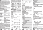
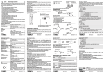
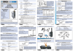
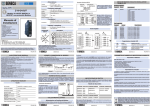
Modulo acquisizione 4 ingressi per
Termocoppia o mV
COLLEGAMENTI ELETTRICI
Z-4TC-D
CARATTERISTICHE GENERALI
Interfaccia per PLC su I/O digitali standard (solo DC).
Ingresso per termocoppie e tensione a basso livello.
Tempo di campionamento impostabile 450 ms @ 14bit+segno, 240 ms @
13bit+segno.
Protezione ingressi fino a 60 V.
Isolamento degli ingressi 1500Vac rispetto ai restanti circuiti in bassa tensione.
Possibilità di cablaggio facilitato dell'alimentazione per mezzo di un bus alloggiabile
nella guida DIN, in alternativa ai morsetti.
Distanza di collegamento fino a 100 m (con cavo schermato).
La tensione di alimentazione deve essere compresa tra 19
19 ÷ 28 V
e 40 Vcc (polarità indifferente) oppure 19 e 28 Vca; vedere 2
anche la sezione NORME DI INSTALLAZIONE.
19 ÷ 40 V=
3
I Iimiti superiori non devono essere superati, pena
2.5 W
gravi danni al modulo.
E' necessario proteggere la sorgente di alimentazione da eventuali guasti del modulo
mediante fusibile opportunamente dimensionato. L'alimentazione del modulo può
essere effettuata tramite gli appositi connettori da guida DIN
INGRESSI DI MISURA
Canale 1
8+
SPECIFICHE TECNICHE
Comunicazione con
PLC:
Ingresso Tensione:
Canale 2
9+
7
19-40 Vcc, 19-28 Vca 50-60Hz , max 2W; 1.5W @ 24 Vcc
Alimentazione:
Porta di comunicazione: Seriale RS232 sul frontale utilizzabile per controllo e setup
del modulo.
Seriale sincrona a tre fili: CLOCK, DATA, STROBE, livelli
standard 24V pnp.
bipolare con f.s. 80 mV, impedenza ingresso > 10 Mohm,
risoluzione 5uV (10 uV @ 14bit).
Ingresso Termocoppia: tipo J,K,R,S,T,B,E,N; risoluzione 5uV (10uV @14bit),
impedenza ingresso > 10 Mohm, rilevamento interruzione TC.
Errori:
Tensione:
Termocoppie J,K,E,T:
Termocoppie R,S:
Termocoppia B (3):
Comp. Giunto freddo:
Condizioni ambientali:
Stab. Termica Altro
Calibrazione Linearità
1% d.s. (2)
0,01% /°C
0,02%
0,1% d.l.
1% d.s. (2)+(1)
0,01% /°C
1°C oltre 0°C
0,1% d.l.
1% d.s. (2)+(1)
1°C oltre 250°C 0,01% /°C
0,1% d.l.
1% d.s. (2)+(1)
3°C oltre 600°C 0,01% /°C
0,1% d.l.
<2 °C tra 10 e 40 °C ambiente
Temperatura:0..55°C , umidità min:30% , max 90% a 40°C
non condensante
Grado di protezione:
Peso, Dimensioni:
IP20
140 g., 100 x 112 x 17,5 mm
MI000664-I/E
ITALIANO - 1/8
Normative:
Lo strumento è conforme alle seguenti normative:
EN50081-2 (emissione elettromagnetica, ambiente
industriale)
EN50082-2 (immunità elettromagnetica, ambiente industriale)
EN61010-1 (sicurezza)
Tutti i circuiti devono essere isolati con doppio isolamento dai
circuiti sotto tensione pericolosa. Il trasformatore di
alimentazione deve essere a norma EN60742: trasformatori
di isolamento e trasformatori di sicurezza.
Note: - Usare con conduttori in rame. - Usare in ambienti con
grado di inquinamento 2. - L’alimentatore deve essere di
Classe 2. - Se alimentato da un alimentatore isolato limitato
in tensione/ limitato in corrente, un fusibile di portata max. di
2.5 A deve essere installato in campo.
(1) influenza della resistenza dei cavi 0.5uV/ohm.
(2) per eventuali interferenze elettromagnetiche
(3) campo misurabile da 362°C - 1800°C
PROGRAMMAZIONE E DESCRIZIONE REGISTRI INTERNI
ALIMENTAZIONE
Canale 3
10+
7
Canale 4
11+
12
IMPORTANTE
Per la programmazione iniziale e la prova del prodotto è
disponibile un software denominato Z-PROG scaricabile dal sito
www.seneca.it
Il tool di programmazione Z-PROG permette di impostare il funzionamento del modulo
Z-4TC-D per adattarlo alle esigenze dell'utente. Per l'utilizzo del tool dovrà essere
disponibile il cavetto di collegamento tra PC e modulo acquistabile presso SENECA
(codice Z-PC). Lo spinotto del cavetto dovrà essere inserito nella presa posta sul
frontale del modulo; durante la programmazione il modulo deve essere alimentato.
Nella tabella seguente sono descritti i registri interni modificabili e/o leggibili mediante il
tool; alcuni di essi sono gli stessi che vengono letti dal PLC. Questi ultimi sono
evidenziati con il simbolo
ad indicare la loro 'visibilità' dal PLC. Per comodità,
non sono riportati i registri dei canali 2,3,4 in quanto identici per tutti i canali.
$
12
Input 1.InType Tipo di ingresso per il canale 1;
0 = mV, campo di misura: 80..+80mV = -16000..+16000.
1 = TC J, campo di misura: -200..1150°C
2 = TC K, campo di misura: -250..1300°C
3 = TC R, campo di misura: 0..1750°C
4 = TC S, campo di misura: 0..1750 °C
5 = TC T, campo di misura: -200..400 °C
6 = TC B, campo di misura: 362..1800 °C
7 = TC E, campo di misura: -200..1000 °C
8 = TC N, campo di misura: -200..1300 °C
NOTA 1: per evitare errori di misura causati da disturbi esterni si raccomanda di
cortocircuitare i canali di ingresso termocoppia eventualmente non utilizzati.
NOTA 2: dato che il negativo degli ingressi è comune, non è possibile collegare il
modulo a termocoppie non isolate dalle parti metalliche degli impianti dove sono
installate.
INTERFACCIA CON PLC
L'interfaccia PLC è basata su tre segnali di tipo PNP adatta ad essere collegata alla
maggior parte dei PLC in commercio.
Essa è costituita da un segnale di CLOCK generato dal PLC (uscita a transistor), da un
segnale di DATA e da un segnale di STROBE generati dal modulo. Ad ogni ciclo di
programma il PLC commuta un segnale di CLOCK (vedi diagramma di temporizzazione);
il modulo a sua volta presenta sull'uscita DATA un bit degli 80 (max) previsti, 16 per ogni
dato completo.
Il modulo genera anche un segnale di STROBE in corrispondenza della fine della
sequenza di bit, che indica al PLC che i dati sono completi; il PLC dovrà inserire in un
registro a scorrimento lo stato del segnale DATA in corrispondenza della
commutazione negativa del segnale CLOCK (in questo istante il segnale è sicuramente
valido, tenendo anche in conto il tempo di ritardo dell'ingresso digitale del PLC). Quando il
segnale di STROBE è positivo, i dati sono completi e possono essere memorizzati.
In tal modo un qualsiasi PLC può agevolmente leggere i 4 canali analogici disponibili con
tempi di rinfresco che sono comparabili con i tempi di acquisizione del modulo stesso. Il
tempo di acquisizione può essere calcolato come segue: tempo di ciclo del PLC x Numero
canali x 32; se il tempo di ciclo è di 5 ms, si ottiene un tempo di acquisizione di 640 ms.
MI000664-I/E
Input 1.Filter
0..6
COLLEGAMENTI VERSO IL PLC
NORME DI INSTALLAZIONE
Il modulo è progettato per essere montato su guida DIN 46277, in posizione
verticale.
Per un funzionamento ed una durata ottimale, bisogna assicurare una
adeguata ventilazione al/ai moduli, evitando di posizionare canaline o altri
oggetti che occludano le feritoie di ventilazione.
Evitare il montaggio dei moduli sopra ad apparecchiature che generano
calore; è consigliabile il montaggio nella parte bassa del quadro.
Schema di realizzazione del cavetto Z-PC per la programmazione mediante PC. Il
cavetto può essere richiesto come accessorio (codice PM001600).
Filtro su misura, valori impostabili da 0 a 6, corrispondenti a:
0 = nessun filtro, 1 = filtro minimo …. 6 = filtro massimo.
Flags indicatori di stato, vedere oltre per dettagli.
$ STATUS
della misura del canale 1: in decimi di grado C se
$ Input 1.Reading Valore
l'ingresso è TC, 1 unità = 5 uV se l'ingresso è mV.
Smaltimento dei rifiuti elettrici ed elettronici (applicabile nell’Unione
Europea e negli altri paesi con servizio di raccolta differenziata).
Il simbolo presente sul prodotto o sulla sua confezione indica che il prodotto
non verrà trattato come rifiuto domestico. Sarà invece consegnato al centro di
raccolta autorizzato per il riciclo dei rifiuti elettrici ed elettronici. Assicurandovi
che il prodotto venga smaltito in modo adeguato, eviterete un potenziale
impatto negativo sull’ambiente e la salute umana, che potrebbe essere
causato da una gestione non conforme dello smaltimento del prodotto. Il
riciclaggio dei materiali contribuirà alla conservazione delle risorse naturali.
Per ricevere ulteriori informazioni più dettagliate Vi invitiamo a contattare
l’ufficio preposto nella Vostra città, il servizio per lo smaltimento dei rifiuti o il
fornitore da cui avete acquistato il prodotto.
Dettagli del registro
STATUS:
ITALIANO - 3/8
La programmazione necessaria per il PLC è molto ridotta: per il PLC SIEMENS S7-200
sono sufficienti 10 righe di Ladder Diagram (vedere allegato) per poter leggere gli ingressi
analogici, corrispondenti a circa 187 byte di spazio di programma.
Non è necessario leggere tutti i canali: mediante il tool di programmazione Z-PROG è
possibile decidere quali sono i canali che verranno inviati al PLC. Con il medesimo tool
è possibile inoltre scegliere svariati modi di funzionamento del modulo: campo di
misura , filtro, tipo di serializzazione, tipo di dato inviato al PLC ecc.
Per quanto riguarda invece l'interfaccia con il PLC, nel riquadro PLC Interface
Settings possono essere selezionati i canali da leggere da parte del PLC, il tipo di
dato (Scaled o Raw), l'inversione della sequenza dei bit (normalmente il primo bit è il
più significativo), l'aumento della velocità di conversione.
Per l'utilizzo del tool consultare la guida in linea.
Questo registro è da considerarsi in formato binario, cioè ciascun bit attivo
(=1) del registro corrisponde ad uno stato di errore o di avvertimento.
In tabella vediamo le funzioni associate ad ogni bit.
MI000664-I/E
.0
.1
.2
ITALIANO - 5/8
Segnalazione:
Nessuna
Nessuna
=1: errore di programmazione EEPROM. Risulta attivo se l'ultima
programmazione di un registro EEPROM è fallita.
.3
=1: errore di programmazione dati. Risulta attivo se l'impostazione del tipo
di ingresso o del valore del filtro non è compreso tra quelli ammessi.
.4
.5
.6
.7
.8
Nessuna
Nessuna
Nessuna
Nessuna
=1: se la misura del canale 1 è superiore al valore massimo permesso per il
tipo di ingresso selezionato (overflow)
.9
=1: se la misura del canale 2 è superiore al valore massimo permesso per il
tipo di ingresso selezionato (overflow)
.10
=1: se la misura del canale 3 è superiore al valore massimo permesso per il
tipo di ingresso selezionato (overflow)
.11
=1: se la misura del canale 4 è superiore al valore massimo permesso per il
tipo di ingresso selezionato (overflow)
.12
.13
.14
.15
Ingresso canale 1 aperto (Burn-out)
Ingresso canale 2 aperto (Burn-out)
Ingresso canale 3 aperto (Burn-out)
Ingresso canale 4 aperto (Burn-out)
MI000664-I/E
INGOMBRI
17,5 mm
I collegamenti indicati si riferiscono in particolare a un PLC SIEMENS S7-200 CPU
224-DC/DC/DC. In ogni caso è possibile l'utilizzo di altri PLC purchè gli ingressi siano
abbastanza veloci ( < 2 ms) e le uscite siano di tipo transistor (non a relè).
CONDIZIONE GRAVOSA DI FUNZIONAMENTO:
ITALIANO - 7/8
112 mm
I
100 mm
Quando i moduli sono montati affiancati è possibile che sia necessario
separarli di almeno 5 mm nel caso in cui la temperatura del quadro sia
superiore a 45°C e sia verificata una condizione di funzionamento
gravoso.
Questo documento è di proprietà SENECA srl. La duplicazione e la riproduzione sono vietate, se non
autorizzate. Il contenuto della presente documentazione corrisponde ai prodotti e alle tecnologie
descritte. I dati riportati potranno essere modificati o integrati per esigenze tecniche e/o commerciali. Il
contenuto della presente
Le condizioni di funzionamento gravoso sono:
Tensione di alimentazione elevata ( > 30Vcc / > 26 Vca ).
Alimentazione di sensori con consumo elevato (> 20 mA).
NOTA: Il montaggio effettuato con gli appositi connettori da guida DIN
fornibili a richiesta, assicura praticità di montaggio e la corretta
ventilazione dei moduli stessi, oltre al risparmio di numerosi cablaggi
elettrici.
MI000664-I/E
ITALIANO - 2/8
R
THE INTERNATIONAL CERTIFICATION NETWORK
ISO9001-2000
MI000664-I/E
ITALIANO - 4/8
MI000664-I/E
ITALIANO - 6/8
SENECA s.r.l.
Via Germania, 34 - 35127 - Z.I. CAMIN - PADOVA - ITALY
Tel. +39.049.8705355 - 8705359 - Fax +39.049.8706287
e-mail: [email protected] - www.seneca.it
MI000664-I/E
ITALIANO - 8/8
4 input acquisition module for
mV or Thermocouple
ELECTRICAL CONNECTIONS
Z-4TC-D
GENERAL SPECIFICATIONS
Interface for PLC on standard digital I/O (only DC).
Input for thermocouple and low voltage circuit.
Sampling time settable at 450 ms @ 14 bit + sign, 240 ms @ 13 bit + sign.
Protection of inputs of up to 60V.
1500V AC input insulation with respect to remaining low voltage circuits.
Facilitated wiring of the power supply and the serial bus by means of a bus that can
be housed in the DIN guide as an alternative to the terminals.
Connection distance up to 100 m (with shielded cable).
The power supply voltage must be between 19 and 40
2
19 ÷ 28 V
Vdc (any polarity) or 19 and 28 V AC; see also section
19 ÷ 40 V=
INSTALLATION.
3
The upper limits must not be exceeded as this can
2.5 W
seriously damage the module.
The power supply source must be protected from any failures in the module by means
of a suitably sized fuse. The module can be powered via the DIN guide connectors.
MEASUREMENT INPUTS
Channel 1
8+
TECHNICAL SPECIFICATIONS
PROGRAMMING AND DESCRIPTION OF INTERNAL
REGISTERS
POWER SUPPLY
Channel 2
9+
7
Channel 3
10+
7
Channel 4
11+
12
12
Power supply:
Communication port:
19-40Vdc, 1928Vac 50-60 Hz , max 2.0W; 1.5W @ 24Vdc
RS232 serial port on front panel can be used for the control
and set-up of the module.
NOTE 1: to avoid measurement errors caused by external disturbances are
recommended short-circuit the thermocouple input channels not used.
PLC communication:
3-wire synchronous serial: CLOCK, DATA, STROBE,
standard levels 24V pnp.
bipolar with 80 mV f.s., input impedance > 10 Mohm,
resolution 5 uV (10 uV @ 14 bit).
NOTE 2: because the negative pole of the inputs is shared, the module cannot be
connected to thermocouples that are not provided with insulation against the
metal parts of the systems in which they are installed.
Voltage input:
Thermocouple input:
J,K,R,S,T,B,E, and N type; resolution 5 uV (10 uV @14 bit),
input impedance > 10 Mohm, TC cut-off detection.
Errors:
Voltage:
Thermocouple J,K,E,T:
Thermocouple R,S:
Thermocouple B (3):
Comp. Cold junction:
Ambient conditions:
Thermal stability Other
Calibration Linearity
1% o.s. (2)
0,01% /°C
0,1% o.r. 0,02%
1% o.s. (2)+(1)
0,1% o.r. 1°C beyond 0°C 0,01% /°C
1% o.s. (2)+(1)
0,1% o.r. 1°C beyond 250°C 0,01% /°C
1% o.s. (2)+(1)
0,1% o.r. 3°C beyond 600°C 0,01% /°C
< 2 °C between 10 and 40 °C ambient.
Temperature: 0..55°C, min. humidity: 30%, max 90% at 40°C
non-condensing
Protection rating:
Weight, dimensions:
IP20
140 g., 100 x 112 x 17,5 mm
MI000664-I/E
Standards:
(1)
(2)
(3)
The Z-PROG programming tool permits the setting of the Z-4TC-D module for
operating adaptation to the needs of the user. The use of the tool requires the
connection cable between the PC and the module which can be purchased directly
from SENECA (code Z-PC). The cable jack must be inserted in the outlet on the front of
the module; during programming, the module must be switched on.
The table below describes the internal registers that can be modified and/or read with
the use of the tool; some of these are the same that are read by the PLC, ad the latter
are distinguished by the symbol
which indicates that they can be read by the
PLC. For reasons of space, the registers for channels 2,3,4 have not been listed
because they are the same for all the channels
$
Input 1.InType Type of input for channel 1;
0 = mV, field of measurement: 80..+80mV = -16000..+16000.
1 = TC J, field of measurement: -200.0.1150°C
2 = TC K, field of measurement: -250.0.1300°C
3 = TC R, field of measurement: 0.0.1750°C
4 = TC S, field of measurement: 0.0.1750 °C
5 = TC T, field of measurement: -200.0.400 °C
6 = TC B, field of measurement: 362.0.1800 °C
7 = TC E, field of measurement: -200.0.1000 °C
8 = TC N, field of measurement: -200..1300 °C
PLC INTERFACE
The PLC interface is based on three PNP-type signals suited for connection to most
PLCs available in the market.
The interface is composed of a CLOCK signal generated by the PLC (transistor output), a
DATA signal and STROBE signal generated by the module. At each program cycle, the
PLC switches a CLOCK signal (see time diagram); the module, in turn presents a bit
sequence of the max. 80 foreseen, 16 for each complete datum on the DATA output.
The module also generates a STROBE signal towards the end of the bit sequence that
informs the PLC that the data are complete; the PLC must enter in a scanning register the
status of the DATA signal corresponding to the negative commutation of the CLOCK
signal (in this moment, the signal is certainly valid, also bearing in mind the time of the
input's delay. When the STROBE signal is positive, the data are complete and can be
memorised.
In this way any PLC can easily read the 4 analogue channels available with refresh
times comparable to the module's own acquisition times. The acquisition time can be
calculated as follows: PLC cycle time x the number of channels x 32; if the cycle time
is 5 ms for example, the acquisition time will be 640 ms.
ENGLISH - 1/8
The instrument complies with the following standards:
EN50081-2 (electromagnetic emission, industrial environment)
EN50082-2 (electromagnetic immunity, industrial environment)
EN61010-1 (safety)
All the circuits must be provided with double insulation
against circuits under dangerous voltage. The power supply
transformer must comply with EN60742 standards for
insulation transformers and safety transformers.
Notes: - Use with copper conductor.- Use in Pollution Degree
2 Environment - Power Supply must be Class 2. - When
supplied by an Isolated Limited Voltage/Limited Current
power supply a fuse rated max 2.5 A shall be installed in the
field
IMPORTANT
A program known as Z-PROG can be downloaded from the
www.seneca.it site for the initial programming and testing of the
product
MI000664-I/E
Input 1.Filter
0..6
PLC CONNECTIONS
influence of the resistance of the 0.5uV/ohm cables.
for any electromagnetic interference present
field measurable from 362°C 1800°C
INSTALLATION
The module has been designed for vertical installation on a DIN 46277
guide.
For optimal operation and long life, adequate ventilation must be provided
for the module(s), avoiding positioning channels that obstruct the
ventilation louvers.
Avoid fitting modules above equipment that generates heat; you are
advised to fit them at the bottom of the panel.
Z-PC cable creation diagram for programming by PC. This cable can be ordered as an
accessory (code PM001600).
Measurement filter, values can be set from 0 to 6,
corresponding to:
0 = no filter, 1 = minimum filter…. 6 = maximum filter
Disposal of Electrical & Electronic Equipment (Applicable throughout
the European Union and other European countries with separate
collection programs)
This symbol, found on your product or on its packaging, indicates that this
product should not be treated as household waste when you wish to dispose of
it. Instead, it should be handed over to an applicable collection point for the
recycling of electrical and electronic equipment. By ensuring this product is
disposed of correctly, you will help prevent potential negative consequences
to the environment and human health, which could otherwise be caused by
inappropriate disposal of this product. The recycling of materials will help to
conserve natural resources. For more detailed information about the recycling
of this product, please contact your local city office, waste disposal service or
thè retail store where you purchased this product.
$
1 measurement value: in tenths of degrees C if the
$ Input 1.Reading Channel
input is TC, 1 unit = 5 uV if the input is mV.
STATUS
Status indicator flags, see below for details.
Details of the register
STATUS:
ENGLISH - 3/8
The programming necessary for the PLC is extremely reduced: the SIEMENS S7-200
PLC requires one 10 lines of Ladder Diagram (see enclosure) in order to read the analogue
inputs; this corresponds to approx. 187 byte of programming space.
It is not necessary to read all the channels: the Z-PROG programming tool can be
used to decide which channels to be sent to the PLC. The tool also permits the
selection of the module's various operating modes: field of measurement, filter, type of
serialisation, type of datum sent to the PLC, etc.
As regards PLC interface instead, the panel PLC Interface Settings can be used to select
the channels to be read by the PLC, the type of datum (Scaled or Raw), the inversion of
the bit sequence (normally the first is the most significant bit), and he increase of the
conversion speed.
Consult the on-line guide for the use of the tool.
This register must be considered in binary format, i.e. each active bit (=1)
of the register corresponds to an error or warning status.
The table shows the functions associated with each bit.
MI000664-I/E
.0
.1
.2
ENGLISH - 5/8
Segnalling:
None
None
=1: EEPROM programming error. Active if the last programming of an
EEPROM register has failed.
.3
=1: data programming error. Active if the setting of the type of input or value
of the filter is not included in the range of acceptability.
.4
.5
.6
.7
.8
None
None
None
None
=1: if the channel 1 measurement is higher than the maximum value
permitted for the type of input selected (overflow)
.9
=1: if the channel 2 measurement is higher than the maximum value
permitted for the type of input selected (overflow)
.10
=1: if the channel 3 measurement is higher than the maximum value
permitted for the type of input selected (overflow)
.11
=1: if the channel 4 measurement is higher than the maximum value
permitted for the type of input selected (overflow)
.12
.13
.14
.15
channel 1 input open (Burn-out)
channel 2 input open (Burn-out)
channel 3 input open (Burn-out)
channel 4 input open (Burn-out)
MI000664-I/E
OVERALL DIMENSIONS
17,5 mm
Although the connections indicated regard a SIEMENS S7-200 CPU 224-DC/DC/DC
PLC in particular, other PLCs can also be used provided that their inputs are fast
enough ( < 2 ms) and their outputs are transistor and not relay type.
HARSH OPERATING CONDITIONS:
When the modules are fitted side by side it may be necessary to
separate them by at least 5 mm if the panel temperature is above 45°C
and operating conditions are harsh.
100 mm
TIMING DIAGRAM
The following constitute harsh operating conditions:
High power supply voltage (> 30Vdc / > 26 V AC ).
Power supply for sensors with high consumption (> 20 mA).
This document is property of SENECA srl. Duplication and reprodution are forbidden, if not authorized.
Contents of the present documentation refers to products and technologies described in it. All technical
data contained in the document may be modified without prior notice Content of this documentation is
subject to periodical revision.
NOTE: Use of the DIN guide connectors supplied on request ensures
practical fitting and correct ventilation of the modules, in addition to
reducing the number of electrical cables.
R
THE INTERNATIONAL CERTIFICATION NETWORK
ISO9001-2000
MI000664-I/E
ENGLISH - 2/8
ENGLISH - 7/8
112 mm
EN
MI000664-I/E
ENGLISH - 4/8
MI000664-I/E
ENGLISH - 6/8
SENECA s.r.l.
Via Germania, 34 - 35127 - Z.I. CAMIN - PADOVA - ITALY
Tel. +39.049.8705355 - 8705359 - Fax +39.049.8706287
e-mail: [email protected] - www.seneca.it
MI000664-I/E
ENGLISH - 8/8