1
961.139
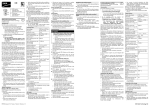
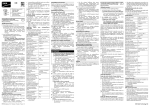
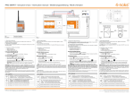
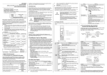
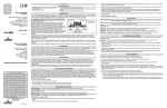
A LED‑Anzeige/
LED display/
Affichage DEL/
Segnalazioni dei LED
B Sensortaste/
Touch key/
Touche tactile/
Tasto sensore
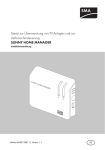
SMA Funksteckdose
mit Bluetooth® Wireless Technology
DE
Installationsanleitung
Bestimmungsgemäße Verwendung
Die SMA Funksteckdose ist
1. ein Zubehörteil für den Sunny Home Manager.
Steuerung über Sunny Home Manager
Für die Steuerung über den Sunny Home
Manager, beachten Sie ausschließlich die
Anleitungen des Sunny Home Manager.
2. ein Repeater zwischen Geräten mit
SMA Bluetooth® Wireless Technology.
Verwendung als Repeater
Dieses Dokument gilt ausschließlich für die
Verwendung der SMA Funksteckdose als
Repeater.
Setzen Sie die SMA Funksteckdose ausschließlich
nach den Angaben dieses Dokuments oder der Anleitungen des Sunny Home Manager ein. Ein anderer
Einsatz kann zu Sach- oder Personenschäden führen.
Dieses Dokument gilt für den Gerätetyp
„BT‑SOCKET‑10“ ab Firmware-Version 1.00.0.R
(siehe Typenschild).
Dieses Dokument ist für Endanwender und Fachkräfte.
Einige in diesem Dokument beschriebenen Tätigkeiten
dürfen nur von Fachkräften mit entsprechender Qualifikation durchgeführt werden. Diese Tätigkeiten sind
durch einen Hinweis gekennzeichnet. Die Fachkräfte
müssen über folgende Qualifikationen verfügen:
• Ausbildung für die Installation und Inbetriebnahme
von elektrischen Geräten.
• Kenntnis der einschlägigen Normen und
Richtlinien.
Die beigefügten Dokumentationen sind Bestandteil
des Produkts.
• Dokumentationen lesen, beachten und jederzeit
zugänglich aufbewahren.
Die SMA Funksteckdose ist für die Verwendung in Mitgliedsstaaten der EU zugelassen. Die SMA Funksteckdose ist ausschließlich für den Einsatz im Innenbereich
geeignet.
• SMA Funksteckdose nur an normgerecht installierte Steckdosen mit Schutzkontakt anschließen.
• Nur Verbraucher an SMA Funksteckdose
anschließen, die für den Spannungs- und Leistungsbereich der SMA Funksteckdose geeignet sind.
Sicherheitshinweise
Lebensgefahr durch Stromschlag
An den spannungsführenden Bauteilen liegen
lebensgefährliche Spannungen an.
• SMA Funksteckdose nur in trockener Umgebung
(z. B. nicht in Feuchträumen) verwenden und von
Flüssigkeiten fernhalten.
• Nur geeignete Stecker in SMA Funksteckdose
stecken.
• SMA Funksteckdose vor dem Reinigen aus der
Steckdose ziehen und nur mit einem trockenen
Tuch reinigen.
BTFSD-IA-de-en-fr-it-11 | Version / Versione 1.1
Die SMA Funksteckdose beinhaltet ein Relais mit
μ‑Kontakt.
• Für eine sichere Trennung vom Stromnetz die
SMA Funksteckdose von der Steckdose entfernen.
Gefahr durch unbeabsichtigtes Schalten
SMA Funksteckdose kann in Verbindung mit einem
Sunny Home Manager über das Sunny Portal
geschaltet werden (siehe Anleitungen des
Sunny Home Manager).
• Keine Verbraucher an SMA Funksteckdose anschließen, die bei unbeabsichtigtem Schalten
Personen gefährden oder Schäden verursachen
können.
Beschädigung der SMA Funksteckdose
Durch
unsachgemäßen Betrieb
kann
die
SMA Funksteckdose beschädigt werden.
• SMA Funksteckdosen nicht ineinander gesteckt betreiben.
Technische Daten
Eingangsspannung
Frequenz
Maximaler Strom
Stromaufnahme
Max. Schaltleistung bei
ohmscher Last
Max. Schaltleistung bei
Lampenlast
Max. Schaltleistung bei
induktiver Last (cos φ > 0,65)
Umgebungstemperatur
Relative Luftfeuchtigkeit*
Schutzart**
Max. Höhe über NHN
100 V … 240 V
50 Hz / 60 Hz
16 A
0,25 W … 1,5 W
3 680 W
600 W
1 200 VA
− 5 °C … +65 °C
5 % … 95 %
IP20
3 000 m
* nicht kondensierend
** nach IEC 60529
Lieferumfang
Kontrollieren Sie den Lieferumfang auf Vollständigkeit
und äußerlich sichtbare Beschädigungen.
• 1 SMA Funksteckdose
• 1 Installationsanleitung
• 1 Beiblatt
LED-Zustände
Obere waagerechte LED:
• Grün leuchtend: SMA Funksteckdose ist eingeschaltet. Verbraucher kann Strom entnehmen.
• Orange leuchtend: SMA Funksteckdose ist ausgeschaltet. Verbraucher kann keinen Strom entnehmen
• Rot leuchtend: System startet oder Update‑Vorgang läuft. SMA Funksteckdose nicht aus Steckdose ziehen. Anderenfalls kann die SMA Funksteckdose beschädigt werden.
Untere waagerechte LED:
• Blau leuchtend: gute SMA Bluetooth Verbindung
• Blau blinkend: kritische SMA Bluetooth
Verbindung
Senkrechte LEDs:
• Grün leuchtend: Sensortaste ist betriebsbereit.
Standardeinstellungen herstellen ist möglich (siehe
Abschnitt „Standardeinstellungen herstellen“).
• Grün blinkend: SMA Funksteckdose wird
initialisiert.
Anforderungen an Installationsort
☐ Steckdose befindet sich an geeigneter Stelle
zwischen den Geräten mit kritischer Verbindungsqualität.
☐ Abstand zu Geräten, die das 2,4-GHz-Frequenzband nutzen (z. B. WLAN-Geräte, Mikrowellenherde), beträgt mindestens 1 m.
Inbetriebnahme
GEFAHR
Lebensgefahr durch Stromschlag durch
spannungsführende Bauteile des Wechselrichters.
• Nur Fachkräfte dürfen am Wechselrichter
arbeiten.
• Vor allen Arbeiten am Wechselrichter den
Wechselrichter AC- und DC-seitig freischalten (siehe Installationsanleitung des Wechselrichters).
1. Anlage außer Betrieb nehmen (siehe Anleitungen
der angeschlossenen Geräte). Dadurch stellen Sie
sicher, dass die SMA Funksteckdose an der Stelle
ins SMA Bluetooth Netzwerk eingebunden wird,
an der die Funklücke besteht.
2. SMA Funksteckdose in Steckdose stecken.
☑ Obere waagerechte LED (A) leuchtet ca.
10 Sekunden rot.
3. Sobald LED‑Anzeige „0“ anzeigt, die Sensortaste
(B) so oft antippen, bis NetID der Anlage
angezeigt wird.
4. Um NetID zu übernehmen, 5 Sekunden warten.
5. Anlage wieder in Betrieb nehmen (siehe Anleitungen der angeschlossenen Geräte).
☑ Ca. 2 Minuten warten bis untere waagerechte LED
blau leuchtet.
✖ Untere waagerechte LED blinkt blau?
SMA Bluetooth Verbindung ist kritisch.
• Wenn möglich anderen Installationsort wählen.
• Wenn kein anderer Installationsort möglich ist,
eine zusätzliche SMA Funksteckdose oder
einen SMA Bluetooth Repeater verwenden.
✖ Untere waagerechte LED ist aus?
Keine SMA Bluetooth Verbindung.
• Sicherstellen, dass an SMA Funksteckdose und
den Geräten der Anlage dieselbe NetID eingestellt, ist (siehe Abschnitt „NetID ändern“).
• Wenn möglich anderen Installationsort wählen.
• Wenn kein anderer Installationsort möglich ist,
eine zusätzliche SMA Funksteckdose oder
einen SMA Bluetooth Repeater verwenden.
NetID ändern
1. Sensortaste gedrückt halten, bis LED‑Anzeige letzte eingestellte NetID anzeigt.
2. Sensortaste so oft antippen, bis gewünschte NetID
angezeigt wird.
3. Um NetID zu übernehmen, 5 Sekunden warten.
Standardeinstellungen herstellen
1. SMA Funksteckdose aus Steckdose ziehen und
erneut in Steckdose stecken.
☑ Obere waagerechte LED leuchtet ca.
10 Sekunden rot.
2. Sobald die senkrechten LEDs grün leuchten,
Sensortaste gedrückt halten, bis die obere
waagerechte LED rot leuchtet.
☑ LED‑Anzeige zeigt „0“ an.
SMA Funksteckdose ein-/ausschalten
1. Um SMA Funksteckdose einzuschalten, Sensortaste antippen.
☑ Obere waagerechte LED leuchtet grün.
SMA Funksteckdose wechselt hörbar in gewählten
Betriebsmodus.
2. Um
SMA
Funksteckdose
auszuschalten,
Sensortaste antippen.
☑ Obere waagerechte LED leuchtet orange.
SMA Funksteckdose wechselt hörbar in gewählten
Betriebsmodus.
Entsorgung
SMA Funksteckdose nach den am Installationsort
geltenden Entsorgungsvorschriften für Elektronikschrott entsorgen.
SMA Radio-Controlled Socket
with Bluetooth® Wireless Technology
EN
Installation manual
Intended Use
The SMA radio-controlled socket is
1. an accessory to the Sunny Home Manager.
Control via Sunny Home Manager
For instructions on how to control the SMA
radio-controlled socket via the
Sunny Home Manager, refer to the manuals of
the Sunny Home Manager only.
2. a repeater for devices with SMA Bluetooth®
Wireless Technology.
Use as a repeater
This document exclusively applies to the use of
the SMA radio-controlled socket as a repeater.
The SMA radio-controlled socket must only be used in
accordance with this document or the manuals for the
Sunny Home Manager. Any other use may result in
personal injury or property damage.
This document is valid for device type "BT-SOCKET-10"
as of firmware version 1.00.0.R (see type label).
This document is intended for end users and skilled
persons. Some of the tasks described in this document
may only be performed by skilled persons with the
appropriate qualifications. These tasks are identified
by an information note. Skilled persons must have the
following qualifications:
• Training in the installation and commissioning of
electrical devices.
• Knowledge of the applicable standards and
guidelines
The enclosed documentation is an integral part of this
product.
• The documentation must be read, observed and
always kept in a convenient place for future
reference.
The SMA radio-controlled socket is approved for the
use in all EU member states. The SMA radio-controlled
socket is designed for indoor use only.
• Only connect the SMA radio-controlled socket to
properly installed socket-outlets with a grounding
contact.
• Only connect loads to the SMA radio-controlled
socket which are suitable for its voltage and power
range.
Safety Precautions
Danger to life due to electric shock
Lethal voltages are present in the conductive
components.
• Only use the SMA radio-controlled socket in a dry
environment (e.g., not in damp rooms), and keep
away from liquids.
• Only insert suitable plugs in the
SMA radio-controlled socket.
• Before cleaning, pull the SMA radio-controlled
socket out of the socket-outlet, and clean with a dry
cloth only.
The SMA radio-controlled socket is equipped with a
relay with μ contact.
• Remove the SMA radio-controlled socket from the
electricity grid for safe disconnection.
Risk of inadvertent switching
The SMA radio-controlled socket used in conjunction
with the Sunny Home Manager can be switched via
the Sunny Portal (see manuals for the Sunny Home
Manager).
• Never connect loads to an SMA radio-controlled
socket which could endanger persons or cause
damage if inadvertently switched on.
Damage to the SMA Radio-Controlled Socket
If the SMA radio-controlled socket is not operated
properly, it could be damaged.
• Do not operate SMA radio-controlled sockets
when they are plugged into each other.
Technical Data
Input voltage
Frequency
Maximum current
Current consumption
Max. switching power with
resistive load
Max. switching power with
lamp load
Max. switching power with
inductive load (cos φ > 0.65)
Ambient temperature
Relative humidity*
Degree of protection**
Max. height
(above mean sea level)
100 V ... 240 V
50 Hz / 60 Hz
16 A
0.25 W … 1.5 W
3,680 W
600 W
1,200 VA
− 5°C … +65°C
5% … 95%
IP20
3,000 m
* non-condensing
** according to IEC 60529
Scope of Delivery
Check the delivery for completeness and any visible
external damage.
• 1 x SMA radio-controlled socket
• 1 x installation manual
• 1 x supplementary sheet
LED States
Upper horizontal LED:
• Glowing green: SMA radio-controlled socket is
switched on. Load can draw electricity.
• Glowing orange: SMA radio-controlled socket is
switched off. Load cannot draw electricity.
• Glowing red: system is in the start-up or update
phase. Do not pull the SMA radio-controlled
socket out of the socket-outlet. Otherwise, the
SMA radio-controlled socket could be damaged.
Lower horizontal LED:
• Glowing blue: good SMA Bluetooth connection
• Flashing blue: critical SMA Bluetooth connection
Vertical LEDs:
• Glowing green: touch key is ready for operation.
Establishing the default settings is possible
(see Section "Establishing the default settings").
• Flashing green: SMA radio-controlled socket is
initializing.
Requirements for the Installation Site
☐ Socket-outlet is located in a suitable position
between devices with critical signal quality.
☐ A minimum distance of 1°m to devices using the
2.4 GHz frequency band (e.g. WLAN devices,
microwave ovens) is observed.
Commissioning
3. As soon as the LED display shows "0", tap the
touch key (B) several times until the NetID of the
plant is displayed.
4. Wait five seconds to adopt the NetID.
5. Recommission the plant (see the manuals of the
connected devices).
☑ Wait approx. two minutes until the lower
horizontal LED is glowing blue.
✖ If the lower horizontal LED is flashing blue:
SMA Bluetooth connection is critical.
• If possible, move to another installation site.
• If no other installation location is possible, use
an additional SMA radio-controlled socket or
an SMA Bluetooth Repeater.
✖ If the lower horizontal LED is off:
No SMA Bluetooth connection.
• Make sure that the SMA radio-controlled
socket and the plant devices are set to the same
NetID (see Section "Change NetID").
• If possible, move to another installation site.
• If no other installation location is possible, use
an additional SMA radio-controlled socket or
an SMA Bluetooth Repeater.
Changing the NetID
1. Keep the touch key pressed until the LED display
shows the previously set NetID.
2. Tap the touch key several times until the desired
NetID is displayed.
3. Wait five seconds to adopt the NetID.
Establishing the Default Settings
1. Pull out and reinsert the SMA radio-controlled
socket into the socket-outlet.
☑ Upper horizontal LED glows red for approximately
ten seconds.
2. As soon as the vertical LEDs are glowing green,
keep the touch key pressed until the upper horizontal LED is glowing red.
☑ LED display shows "0".
Switching on/off the SMA radio-controlled
socket
1. To switch on the SMA radio-controlled socket, tap
the touch key.
☑ Upper horizontal LED is glowing green.
The SMA radio-controlled socket audibly switches
to the selected operating mode.
2. To switch off the SMA radio-controlled socket, tap
the touch key.
☑ Upper horizontal LED is glowing orange.
The SMA radio-controlled socket audibly switches
to the selected operating mode.
DANGER
Risk of lethal electric shock when touching
conductive components of the inverter
• Only skilled persons may work on the
inverter.
• Prior to performing any work on the inverter,
disconnect the inverter from any voltage
sources on the AC and DC sides (see inverter
installation manual).
1. Decommission the plant (see manuals of the
connected devices). This will ensure that the
SMA radio-controlled socket is integrated into the
SMA Bluetooth network at the point where the
dead zone occurs.
2. Insert the SMA radio-controlled socket into the
socket-outlet.
☑ Upper horizontal LED (A) glows red for approx.
10 seconds.
SMA Solar Technology AG
Prise radiocommandée SMA
avec Bluetooth® Wireless Technology
FR
Instructions d’installation
Utilisation conforme
La prise radiocommandée SMA est
1. un accessoire pour le Sunny Home Manager.
Commande via Sunny Home Manager
Pour une commande via le Sunny Home
Manager, veuillez respecter exclusivement les
instructions d’installation du Sunny Home
Manager.
2. un répéteur entre les appareils avec Bluetooth®
Wireless Technology.
Utilisation en tant que répéteur
Ce document est uniquement valable pour
l’utilisation de la prise radiocommandée SMA
en tant que Repeater.
Utilisez la prise radiocommandée SMA exclusivement
selon les données de ce document ou selon les instructions du Sunny Home Manager. Une utilisation divergente risque de provoquer des dommages corporels
ou matériels.
Ce document s’applique au type d’appareil
« BT-Socket-10 » à partir de la version du micrologiciel 1.00.0.R. (voir plaque signalétique).
Ce document est destiné aux utilisateurs finaux et
au personnel qualifié. Certaines des opérations
décrites dans ce document doivent uniquement être
réalisées par du personnel qualifié possédant les qualifications requises. Ces activités sont marquées par
une remarque. Le personnel qualifié doit présenter les
qualifications suivantes :
• formation à l’installation et la mise en service des
équipements électriques,
• connaissance des normes et directives pertinentes.
Les documents ci-joints font partie intégrante du produit.
• Lisez les documents, respectez-les et conservez-les
de sorte qu’ils soient accessibles à tout moment.
La prise radiocommandée SMA est homologuée pour
les états membres de l’UE. La prise radiocommandée
SMA doit être utilisée uniquement en intérieur.
• Raccordez la prise radiocommandée SMA uniquement à des prises de courant installées selon les
normes avec mise à la terre.
• Raccordez à la prise radiocommandée SMA uniquement des consommateurs adaptés à la plage
de tension et de puissance des prises radiocommandées de SMA.
Consignes de sécurité
Danger de mort par choc électrique
Des tensions mortelles sont présentes au niveau des
composants conducteurs.
• Utilisez la prise radiocommandée SMA uniquement dans un environnement sec (pas dans des
pièces humides par exemple) et tenez-la éloigné
des liquides.
• Branchez uniquement des fiches appropriées dans
des prises radiocommandées SMA.
• Pour nettoyer la prise radiocommandée SMA,
débranchez-la de la prise de courant et nettoyezla uniquement avec un tissu sec.
La prise radiocommandée SMA est équipée d’un
relais avec un contact μ.
• Enlevez la prise radiocommandée SMA de la prise
de courant pour assurer une coupure du réseau
électrique public sûre.
Danger en cas de commutation involontaire
La prise radiocommandée SMA peut être allumée par
le biais d’un Sunny Home Manager via le Sunny
Portal (voir les instructions du Sunny Home Manager).
• Ne raccordez pas des consommateurs à la prise
radiocommandée SMA qui pourraient entraîner
des dommages corporels et matériels en cas de
commutation involontaire.
BTFSD-IA-de-en-fr-it-11
Endommagement de la prise radiocommandée
SMA
L’opération non conforme pourrait endommager la
prise radiocommandée SMA.
• N’exploitez pas des prises radiocommandées
SMA si elles sont enfichées l’une à l’autre.
Données techniques
Tension d’entrée
Fréquence
Courant maximal
Consommation de courant
Puissance de commutation
maximale en charge ohmique
Puissance de commutation
maximale en charge de lampe
Puissance de commutation
maximale en charge inductive
(cos φ > 0,65)
Température ambiante
Humidité relative de l’air*
Indice de protection**
Hauteur max. au-dessus du
niveau moyen de la mer
100 V à 240 V
50 Hz/60 Hz
16 A
0,25 W à 1,5 W
3 680 W
600 W
1 200 VA
− 5 °C à +65 °C
5 % à 95 %
IP20
3 000 m
* sans condensation
** selon IEC 60529
Contenu de la livraison
Vérifiez que la livraison est complète et ne présente
pas de dommages extérieurs apparents.
• 1 x prise radiocommandée SMA
• 1 x instructions d’installation
• 1 x supplément
États des DEL
DEL supérieure horizontale :
• Allumée en vert : la prise radiocommandée SMA
est activée. Le consommateur peut prélever du
courant.
• Allumée en orange : la prise radiocommandée
SMA est désactivée. Le consommateur ne peut pas
prélever de courant.
• Allumée en rouge : le système démarre ou un processus de mise à jour est en cours. Ne débranchez
pas la prise radiocommandée SMA de la prise de
courant Cela pourrait endommager la prise
radiocommandée SMA.
DEL inférieure horizontale :
• Allumée en bleue : bonne connexion SMA
Bluetooth
• Clignotante en bleue : connexion SMA Bluetooth
critique
DEL verticales :
• Allumée en vert : la touche tactile est prête au service. Il est possible d’établir les réglages standards
(voir section « Établir les réglages standards »)
• Clignotante en vert : la prise radiocommandée
SMA est initialisée.
Conditions requises sur le lieu d’installation
☐ La prise de courant se trouve à un endroit
approprié entre les appareils présentant une
qualité de connexion critique.
☐ Distance d’au moins 1 m aux appareils utilisant la
bande de fréquence de 2,4 GHz (par exemple
équipements WLAN ou fours à micro-ondes).
Mise en service
DANGER
Danger de mort par choc électrique dû aux
composants sous tension de l’onduleur
• Seul du personnel qualifié peut effectuer des
travaux sur l’onduleur.
• Avant toute intervention sur l’onduleur,
déconnectez celui-ci côtés AC et DC (comme
décrit dans les instructions d’installation de
l’onduleur).
1. Mettez l’installation hors service (voir les instructions des appareils raccordés).
Ceci permet d’assurer l’intégration de la prise
radiocommandée SMA à l’endroit précis où la
couverture du réseau SMA Bluetooth fait défaut.
2. Branchez la prise radiocommandée SMA dans
une prise de courant.
☑ La DEL supérieure horizontale (A) est allumée en
rouge pendant environ dix secondes.
3. Dès que l’affichage DEL affiche « 0 », tapotez sur
la touche tactile (B) jusqu’à ce que le NetID de
l’installation soit affiché.
4. Attendez cinq secondes avant d’appliquer le
NetID.
5. Remettez l’installation en service (voir instructions
des appareils raccordés).
☑ Attendez environ deux minutes jusqu’à ce que la
DEL bleue inférieure horizontale brille.
✖ La DEL inférieure horizontale bleue clignote ?
La connexion SMA Bluetooth est critique.
• Si possible, choisissez un autre lieu
d’installation.
• S’il n’est pas possible de choisir un autre lieu
d’installation, utilisez une prise radiocommandée SMA supplémentaire ou un
SMA Bluetooth Repeater.
✖ La DEL inférieure horizontale est éteinte ?
Pas de connexion SMA Bluetooth.
• Assurez-vous que le même NetID est réglé au
niveau de la prise radiocommandée SMA et
des appareils de l’installation (voir section
« Modifier NetID »).
• Si possible, choisissez un autre lieu
d’installation.
• S’il n’est pas possible de choisir un autre lieu
d’installation, utilisez une prise radiocommandée SMA supplémentaire ou un
SMA Bluetooth Repeater.
Modifier le NetID
1. Maintenez la touche tactile appuyée jusqu’à ce
que l’affichage DEL affiche le dernier NetID réglé.
2. Tapotez sur la touche tactile jusqu’à ce que le
NetID souhaité s’affiche.
3. Attendez cinq secondes avant d’appliquer le
NetID.
Établir les réglages standard
1. Débranchez la prise radiocommandée SMA de la
prise de courant et l’enfichez à nouveau dans la
prise de courant.
☑ La DEL supérieure horizontale est allumée en bleue
pendant environ dix secondes.
2. Dès que les DEL vertes verticales sont allumées,
maintenez la touche tactile appuyée jusqu’à ce
que la DEL supérieure horizontale est allumée en
rouge.
☑ L’affichage DEL indique « 0 ».
Activer et désactiver la prise radiocommandée
SMA
1. Pour activer la prise radiocommandée SMA, tapotez sur la touche tactile.
☑ La DEL supérieure horizontale est allumée en vert.
La prise radiocommandée SMA passe de façon
audible dans le mode de fonctionnement
sélectionné.
2. Pour désactiver la prise radiocommandée SMA,
tapotez la touche tactile.
☑ La DEL supérieure horizontale est allumée en
orange. La prise radiocommandée SMA passe de
façon audible dans le mode de fonctionnement
sélectionné.
Élimination
Éliminez la prise radiocommandée en respectant les
consignes d’élimination relatives aux déchets
d’équipements électriques et électroniques en vigueur
sur le lieu d’installation.
Presa radio SMA
con Bluetooth® Wireless Technology
IT
Istruzioni per l'installazione
Utilizzo conforme
La presa radio SMA è
1. un accessorio di Sunny Home Manager.
Gestione tramite Sunny Home Manager
Per la gestione tramite Sunny Home Manager,
fare riferimento esclusivamente alle istruzioni di
Sunny Home Manager.
2. un repeater tra apparecchi con SMA Bluetooth®
Wireless Technology.
Utilizzo come repeater
Il presente documento è valido esclusivamente
per l'utilizzo della presa radio SMA come
repeater.
La presa radio SMA deve essere utilizzata esclusivamente secondo quanto indicato nel presente documento e nelle istruzioni di Sunny Home Manager. Utilizzi diversi possono provocare danni a persone o cose.
Il presente documento è valido per il tipo di apparecchio “BT-SOCKET-10“ a partire dalla versione
firmware 1.00.0.R. (v. targhetta di identificazione).
Il presente documento è destinato agli utenti finali e
tecnici specializzati. Alcune delle operazioni descritte
nel presente documento devono essere eseguite esclusivamente da tecnici specializzati in possesso di relativa qualifica. Dette operazioni sono contrassegnate
da una nota. I tecnici specializzati devono disporre
delle seguenti qualifiche:
• Formazione relativa all'installazione e alla messa
in servizio di apparecchi elettrici
• Conoscenza delle norme e delle direttive vigenti
La documentazione in allegato è parte integrante del
prodotto.
• Leggere e rispettare la documentazione, che deve
risultare accessibile in qualsiasi momento.
La presa radio SMA è omologata per l'impiego in stati
membri dell'UE. La presa radio SMA è idonea esclusivamente per l'impiego in ambienti interni.
• Collegare la presa radio SMA solo a prese a
norma con contatto di protezione.
• Collegare alla presa radio SMA solo utenze
adeguate al suo campo di tensione e potenza.
Avvertenze di sicurezza
Pericolo di morte per scossa elettrica
Nei componenti conduttori di tensione sono presenti
tensioni pericolose.
• Utilizzare la presa radio SMA solo in ambienti
asciutti ed evitare il contatto con liquidi.
• Inserire nella presa radio SMA solo spine adatte.
• Per la pulizia rimuovere per prima cosa la presa
radio SMA dalla presa e utilizzare poi solo un
panno asciutto.
La presa radio SMA contiene un relè con contatto μ.
• Per una separazione sicura dalla rete pubblica
rimuovere la presa radio SMA dalla presa.
Pericolo da attivazione involontaria
La presa radio SMA può essere attivata in abbinamento a Sunny Home Manager tramite Sunny Portal
(vedere le istruzioni di Sunny Home Mana-ger).
• Non collegare alla presa radio SMA utenze la cui
attivazione involontaria può costituire un pericolo
per persone o causare danni.
Danneggiamento della presa radio SMA
Un funzionamento improprio può danneggiare la
presa radio SMA.
• Non utilizzare le prese radio SMA collegate tra
loro.
Dati tecnici
Tensione d'ingresso
Frequenza
Corrente massima
Assorbimento di corrente
Potenza di commutazione max.
in caso di carico ohmico
Potenza di commutazione max.
in caso di carico lampada
Potenza di commutazione max.
in caso di carico induttivo con un
fattore di sfasamento
cos φ > 0,65
Temperatura ambiente
Umidità relativa dell'aria*
Grado di protezione**
Altezza max. sopra il livello del
mare
100 V ... 240 V
50 Hz / 60 Hz
16 A
0,25 W … 1,5 W
3 680 W
600 W
1 200 VA
− 5 °C … +65 °C
5% … 95%
IP20
3 000 m
* Non condensante
** Secondo IEC 60529
Contenuto della fornitura
Controllare che la fornitura sia completa e non
presenti danni visibili all'esterno.
• 1 presa radio SMA
• 1 manuale di istruzioni per l'installazione
• 1 foglio aggiuntivo
Stati LED
LED orizzontale superiore:
• Verde: la presa radio SMA è attivata. L'utenza può
ricevere corrente.
• Arancione: la presa radio SMA è disattivata.
L'utenza non può ricevere corrente.
• Rosso: avvio del sistema o aggiornamento in corso. Non estrarre la presa radio SMA dalla presa.
In caso contrario la presa radio SMA può subire
danni.
LED orizzontale inferiore:
• Blu: collegamento SMA Bluetooth regolare
• Blu lampeggiante: collegamento SMA Bluetooth
critico
LED verticali:
• Verdi: il tasto sensore è operativo. È possibile
definire impostazioni standard (vedere paragrafo
"definizione impostazioni standard").
• Verdi lampeggianti: la presa radio SMA viene
inizializzata.
Requisiti del luogo di installazione
☐ La presa si trova in un luogo adatto tra i dispositivi
con qualità di connessione critica.
☐ Mantenere una distanza minima di 1 m dagli
apparecchi che utilizzano la banda di frequenza
a 2,4 GHz (ad es. apparecchi WLAN o forni
microonde).
Messa in servizio
PERICOLO
Pericolo di morte per scossa elettrica dovuto
ai componenti sotto tensione dell'inverter.
• Sull'inverter devono operare solo tecnici
specializzati.
• Prima di eseguire qualsiasi intervento
sull'inverter, disinserire l'inverter sul lato CA e
CC (vedere le istruzioni per l'installazione
dell'inverter).
2. Inserire la presa radio SMA nella presa.
☑ Il LED orizzontale superiore (A) si accende per
circa 10 secondi con luce rossa.
3. Quando l'indicatore LED mostra "0", premere più
volte il tasto sensore (B) finché viene visualizzato il
NetID dell'impianto.
4. Attendere 5 secondi per acquisire il NetID.
5. Rimettere in funzione l'impianto (vedere le
istruzioni degli apparecchi collegati).
☑ Attendere circa 2 minuti finché il LED orizzontale
inferiore si accende con luce blu.
✖ Il LED orizzontale inferiore lampeggia con luce
blu?
La connessione SMA Bluetooth è critica.
• Se possibile, scegliere un altro luogo di
installazione.
• Se ciò non è possibile, utilizzare una presa
radio SMA aggiuntiva o uno
SMA Bluetooth Repeater.
✖ Il LED orizzontale inferiore è spento?
Nessuna connessione SMA Bluetooth.
• Assicurarsi che nella presa radio SMA e
negli apparecchi dell'impianto sia impostato lo
stesso NetID (vedere paragrafo "Modifica del
NetID").
• Se possibile, scegliere un altro luogo di installazione.
• Se ciò non è possibile, utilizzare una presa
radio SMA aggiuntiva o uno
SMA Bluetooth Repeater.
Modifica del NetID
1. Tenere premuto il tasto sensore finché l'indicatore
LED mostra l'ultimo NetID impostato.
2. Premere più volte il tasto sensore fino a visualizzare il NetID desiderato.
3. Attendere 5 secondi per acquisire il NetID.
Definizione delle impostazioni standard
1. Estrarre la presa radio SMA dalla presa, quindi
reinserirla.
☑ Il LED orizzontale inferiore si accende per circa
10 secondi con luce rossa.
2. Non appena i LED verticali si accendono con luce
verde, tenere premuto il tasto sensore finché il LED
orizzontale inferiore si accende con luce rossa.
☑ L'indicatore LED mostra "0".
Attivazione/disattivazione della presa radio
SMA
1. Toccare il tasto sensore per attivare la presa radio
SMA.
☑ Il LED orizzontale superiore si accende con luce
verde. Si può sentire il passaggio della presa radio
SMA alla modalità operativa selezionata.
2. Toccare il tasto sensore per disattivare la presa
radio SMA.
☑ Il LED orizzontale superiore si accende con luce
arancione. Si può sentire il passaggio della presa
radio SMA alla modalità operativa selezionata.
Smaltimento
Smaltire la presa radio SMA secondo le norme per lo
smaltimento vigenti per gli apparecchi elettrici nel
luogo di installazione.
1. Disattivare l'impianto (vedere le istruzioni degli
apparecchi collegati). In questo modo ci si assicura che la presa radio SMA sia inserita nel punto
della rete SMA Bluetooth dove sussiste il problema
di connessione.
SMA Solar Technology AG