1
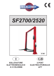
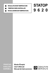
GRUPPO STRUTTURA MOBILE
costituito da due traverse e da due pedane.
Ogni traversa scorre verticalmente tra due colonne.
Come si vede nelle figure seguenti, alle due estremità di ogni traversa sono fissati:
- le pulegge di rinvio (1) della fune di sollevamento,
- gli innesti meccanici di sicurezza (martelletti) (2 e 3).
Il martelletto di stazionamento (pos.3) si inserisce automaticamente durante tutta la fase di salita e nello stazionamento. Deve
essere disinserito elettricamente durante la fase di discesa.
In caso di rottura della fune (figg.7 e 8) si inserisce meccanicamente il martelletto di sicurezza (2) e di conseguenza viene azionato il
microinterruttore funi (4) che provoca l'interruzione della parte elettrica del ponte e l’inserimento del martelletto di stazionamento.
1
Fig.7
MOVABLE STRUCTURE
The movable structure consist of two cross-pieces and two platforms.
Each cross-piece translates vertically between two posts.
As shown in seguent figure, the ends of the cross-pieces are fitted
with the following parts:
- return pulleys (1) for the lift cable,
- mechanical safety devices (wedges) (2 and 3).
The wedge (pos. 3) will engage automatically during lifting and
when the lift is raised. To start the LOWERING cycle the wedges
must be disengaged electrical control when lowering.
In case of failure of the main lifting cable (fig. 7 and 8) the safety
wedge (2) engages mechanically and as consequence the cable
micro switch (4) disables the low voltage circuit and the parking
wedge falls in to parking lock.
4
4
1
Fig.8
2
2
3
3
Le due pedane portaveicoli (Fig. 9) appoggiano sulle traverse.
La pedana sinistra (1) è fissa, mentre la pedana destra (2) è mobile e può scorrere orizzontalmente per adattarsi alle diverse carreggiate dei veicoli. Entrambe sono dotate di arresti fissi di sicurezza
(4) che impediscono al veicolo stesso di oltrepassare accidentalmente la fine della pedana; le rampe di accesso (3), incernierate
sulle pedane, si posizionano verticalmente quando le pedane salgono, bloccando in maniera definitiva il veicolo.
The two platforms (Fig. 9) are supported on the cross-pieces.
The left platform (1) has no adjustment; the right platform (2) is
free to slide across the width of the lifting area to adapt to the track
width of the vehicle being lifted.
Both platforms have fixed wheel stops (4) to stop the vehicle from
going beyond the ends of the platforms;
The access ramps (3), pivoted to the platforms, automatically reach a vertical position when the platforms lift, thereby securing the
vehicle also from the access end.
4
1
2
3
4
3
Fig.9-
Pedane e Traverse
All’interno della pedana fissa (Fig.
10), con accesso dal solo lato inferiore (lato suolo),
si trovano:
- il cilindro idraulico di sollevamento (1);
- la valvola paracadute o di blocco
(2);
- il giogo di attacco (3) delle funi di
acciaio;
- due gruppi pulegge di rinvio (4)
delle funi.
Fig.9
Platforms and cross-pieces
The following components are located beneath the fixed platform (Fig.
10), and are accessible only from
underneath:
- hydraulic lift cylinder (1);
- parachute safety valve (2);
- clevis coupling (3) for the steel
cables;
- two cable return pulley assemblies
(4).
4
1
3
2
Fig.10
8
Interno pedana fissa
4
FIg.10
Interior of the fixed platform