1
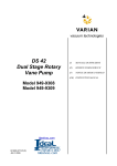
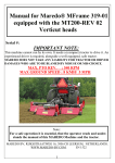
Exhaust Filter
DS-NW25 949-9392
87-900-941-01(D)
JUNE 2004
MANUALE DI ISTRUZIONI
INSTRUCTION MANUAL
Exhaust Filter
ISTRUZIONI PER L’USO .................................................................................................... 1
DESCRIZIONE DEL FILTRO DISOLIATORE ...............................................................................1
CARATTERISTICHE TECNICHE ..................................................................................................1
DIMENSIONI DI INGOMBRO ........................................................................................................1
FUNZIONAMENTO........................................................................................................................1
INSTALLAZIONE DEL FILTRO DISOLIATORE............................................................................2
MANUTENZIONE ..........................................................................................................................2
Drenaggio dell'Olio...............................................................................................................2
Cambio della Cartuccia........................................................................................................2
PARTI DI RICAMBIO ED ACCESSORI.........................................................................................2
INSTRUCTIONS FOR USE................................................................................................. 3
DESCRIPTION OF THE EXHAUST FILTER.................................................................................3
TECHNICAL SPECIFICATION ......................................................................................................3
OUTLINE DRAWING .....................................................................................................................3
OPERATION ..................................................................................................................................3
EXHAUST FILTER INSTALLATION ..............................................................................................4
MAINTENANCE .............................................................................................................................4
Oil Drainage .........................................................................................................................4
Cartridge Changing..............................................................................................................4
REPLACEMENT PARTS AND ACCESSORIES ...........................................................................4
ISTRUZIONI PER L’USO
DESCRIZIONE DEL FILTRO DISOLIATORE
Il filtro di intrappolamento olio NW 25 utilizza cartucce disolianti ad alta efficienza ed ha lo scopo
principale di purificare i gas di scarico dagli aerosol di olio e di eventuali altri liquidi.
DS NW25
,
PERICOLO!
Sostanze allo stato gassoso e di vapore non vengono trattenute dal filtro per cui eventuali gas tossici provenienti dalla pompa devono essere
smaltiti allo scarico del filtro in accordo alle norme
generali per la protezione contro gas velenosi.
Massimo flusso a 1 bar e 20 °C
3
[Nm /h]
90
Caduta di pressione [mbar]
150
Massima pressione permessa [bar]
2.0
Flangia di aspirazione/ scarico
25 KF
Pompe su cui montare il filtro
DS 102 / 202 / 302 /
402 / 602
DIMENSIONI DI INGOMBRO
La figura seguente mostra le dimensioni di ingombro del filtro disoliatore (le dimensioni sono in pollici [mm]).
CARATTERISTICHE TECNICHE
La seguente tabella dettaglia le principali caratteristice del filtro disoliatore.
Modello 949-9392
Le nebbie di olio sono trattenute dalla cartuccia,
dove si aggregano sotto forma di gocce. Queste,
per gravità, si depositano sul fondo del carter.
La cartuccia ha pure la capacità di trattenere particelle solide trascinate dal gas. Queste particelle sono la causa principale di intasamento della cartuccia.
Per evitare che la pressione a monte dell'elemento
filtrante raggiunga valori tali da compromettere il
corretto funzionamento della pompa, è previsto un
dispositivo di sovrappressione che interviene
quando la pressione raggiunge il valore di 1 bar.
Quando la cartuccia è intasata ed il sistema di sicurezza si è innescato, le nebbie di olio vengono
trascinate dal flusso dei gas direttamente dalla
pompa all'ambiente esterno.
E' buona norma, prima di giungere al completo intasamento della cartuccia, sostituire la cartuccia a
intervalli di tempo regolari, dipendenti dal tipo di
applicazione della pompa.
FUNZIONAMENTO
Per questa descrizione, fare riferimento alla figura
seguente.
Il gas in uscita dalla pompa percorre il condotto
(1), attraversa la cartuccia disoliante (2) ed esce
dalla camera (3) circostante.
1
87-900-941-01(D)
ISTRUZIONI PER L’USO
Per sostituire la cartuccia occorre seguire i seguenti passi:
1. Svitare le quattro viti (6).
INSTALLAZIONE DEL FILTRO DISOLIATORE
Il filtro disoliatore si monta sulla pompa unendo la
flangia (4) (vedere la figura precedente) mediante
collare di serraggio e anello di centraggio alla flangia di scarico della pompa.
Il filtro viene fornito montato come mostrato in figura.
!
PERICOLO!
Avere l'accortezza di trattenere i due elementi collegati affinchè questi non vengano scagliati via a
causa della compressione della molla.
MANUTENZIONE
2. Rimuovere la cartuccia (2) e sostituirla con
quella di ricambio.
3. Accostare la testata (7) al tubo facendo attenzione che la molla (8) non esca dal proprio alloggio e che prema la cartuccia contro la sua
sede.
4. Avvitare le quattro viti (6).
Drenaggio dell'Olio
L'olio che si accumula nel carter deve essere rimosso prima che bagni la superficie esterna della
cartuccia disoliante e ne riduca l'efficienza.
L'oblò posto su un lato del carter consente di tenere sotto controllo il livello dell'olio.
Per effettuare l'operazione di drenaggio occorre
svitare il tappo (5).
PARTI DI RICAMBIO ED ACCESSORI
Per avere le giuste parti di ricambio, occorre indicare nell’ordine il tipo di filtro ed il suo numero di
modello (indicato sulla sua etichetta).
Come ricambio è disponibile un kit che contiene le
guarnizioni del filtro ed il filtro stesso, con la seguente denominazione:
Cambio della Cartuccia
La cartuccia disoliante ha un tempo limitato di vita,
che dipende dal tipo di applicazione. L'intasamento della cartuccia fa entrare in funzione il dispositivo di by-pass che invia i gas direttamente dalla
pompa all’ambiente esterno prima che raggiungano pericolose sovrappressioni per la pompa.
In questo caso i fumi d'olio si diffondono nell'ambiente esterno indicando l'avvenuto intasamento
della cartuccia stessa e, per evitare l’inquinamento
dell'ambiente, si consiglia di sostituire la cartuccia.
•
2
DS Exhaust Filter Kit NW 25
(P/N 949-9342)
87-900-941-01(D)
INSTRUCTIONS FOR USE
DESCRIPTION OF THE EXHAUST FILTER
The oil Exhaust Filter NW25 uses high efficiency
oil separating cartridge.
Its function is to purify the exhaust gas from oil or
other liquid aerosol.
DS NW25
3
,
WARNING!
Gases and vapors are not filtered, so toxic gases
from the pump must be disposed according to the
general disposition about toxic gases.
Max. flux at 1 bar and 20 °C [Nm /h]
90
Pressure drop [mbar]
150
Maximum allowed pressure [bar]
2.0
Inlet/outlet flange
25 KF
Applicable pumps
DS 102 / 202 / 302 /
402 / 602
OUTLINE DRAWING
The following figure shows the outline drawing for
the Exhaust Filter (the dimensions are inches
[mm]).
TECHNICAL SPECIFICATION
The following table details the main technical
specifications of the Exhaust Filter.
Modello 949-9392
The oil mist is filtered by the cartridge where it
transforms into drops. The drops deposit on the
carter bottom for the gravity effect.
The cartridge also filters the solid particles from
the gas. These particles are the main cause of the
cartridge clog.
To avoid that the pressure before the filtering element increases so that the pump does not work
properly, an overpressure device is provided that
intervenes when the pressure reaches the 1 bar
value.
When the cartridge is obstructed and the security
system is operating, the oil mist is dragged by the
gas flux from the pump directly to the external ambient.
Before the cartridge is completely obstructed, it is
advisable to change it on a regular basis according
to the pump application.
OPERATION
For the following description refer to the following
figure.
The output gas from the pump flows through the
duct (1), passes the cartridge (2) ed exits from the
surrounding chamber (3).
3
87-900-941-01(D)
INSTRUCTIONS FOR USE
To change the cartridge you must execute the following steps:
1. Unscrew the four screws (6).
EXHAUST FILTER INSTALLATION
The Exhaust Filter is installed on the pump connecting the flange (4) (see the preceding figure) to
the outlet flange of the pump by means of a clamping collar and centering ring.
The filter is factory assembled as shown in the figure.
!
WARNING!
Take care to keep in position the two elements so
that they are not thrown away by the spring compression.
MAINTENANCE
2. Remove the cartridge (2) and insert the new
one.
Oil Drainage
The oil on the carter bottom must be periodically
removed before it reaches the external surface of
the cartridge so that its efficiency is reduced.
The window on a side of the carter allows to check
the oil level.
To drain the oil it is necessary to unscrew the plug
(5).
3. Place the head (7) close to the pipe taking
care that the spring (8) do not exit from its
seat and that it presses the cartridge in its position.
4. Screw the four screws (6).
Cartridge Changing
The cartridge has a limited life time that depends
on the pump application. The cartridge clogging
activates the by-pass device so that the gases
from the pump are directly sent to the external
ambient to avoid dangerous pump overpressures.
In this case the oil mist are diffused into the atmosphere indicating that the cartridge is obstructed and, to avoid the ambient pollution, it is
advisable to change the cartridge.
REPLACEMENT PARTS AND ACCESSORIES
To obtain the correct replacement parts, the order
must contain the filter type and its model number
(it is indicated onto the filter label)
As replacement parts ordering, a filter kit, that contains the filter itself and the relevant gaskets, is
available, with the following description:
•
4
DS Exhaust Filter Kit NW 25
(P/N 949-9342)
87-900-941-01(D)
Request for Return
1.
2.
3.
4.
A Return Authorization Number (RA#) WILL NOT be issued until this Request for Return is completely filled out,
signed and returned to Varian Customer Service.
Return shipments shall be made in compliance with local and international Shipping Regulations (IATA, DOT, UN).
The customer is expected to take the following actions to ensure the Safety of workers at Varian: (a) Drain any oils or
other liquids, (b) Purge or flush all gasses, (c) Wipe off any excess residues in or on the equipment, (d) Package the
equipment to prevent shipping damage, (for Advance Exchanges please use packing material from replacement unit).
Make sure the shipping documents clearly show the RA# and then return the package to the Varian location nearest you.
North and South America
Varian Vacuum Technologies
121 Hartwell Ave
Lexington, MA 02421
Phone : +1 781 8617200
Fax: +1 781 8609252
Europe and Middle East
Varian SpA
Via Flli Varian 54
10040 Leini (TO) – ITALY
Phone: +39 011 9979111
Fax: +39 011 9979330
Asia and ROW
Varian Vacuum Technologies
Local Office
CUSTOMER INFORMATION
Company name: ..………………….……..……………….………………………………..……………………...…………..….
Contact person: Name: ……………………………………..…
Tel: ……………………….…...…………….….…....
Fax: …………………………….…...…..……
E-Mail: ..……………………..…………..…..…..…..
Ship Method: …………….……....…… Shipping Collect #: ………….…..………… P.O.#: ………………….…......………..
Europe only: VAT reg. Number: ………………..……………...
Customer Ship To: ………………………….………
……………..…………………...
………………..………………...
PRODUCT IDENTIFICATION
Product Description
USA only:
Taxable
Non-taxable
Customer Bill To: …………………..……………...
..………………………………...
..………………………………...
Varian P/N
Varian S/N
TYPE OF RETURN (check appropriate box)
Paid Exchange
Paid Repair
Warranty Exchange
Credit
Shipping Error
Evaluation Return
Warranty Repair
Calibration
Purchase Reference
Loaner Return
Other ……………….
HEALTH and SAFETY CERTIFICATION
Varian Vacuum Technologies CAN NOT ACCEPT any equipment which contains BIOLOGICAL HAZARDS or
RADIOACTIVITY. Call Varian Customer Service to discuss alternatives if this requirement presents a problem.
The equipment listed above (check one):
HAS NOT been exposed to any toxic or hazardous materials
OR
HAS been exposed to any toxic or hazardous materials. In case of this selection, check boxes for any materials that
equipment was exposed to, check all categories that apply:
Toxic
Corrosive
Reactive
Flammable
Explosive
Biological
Radioactive
List all toxic or hazardous materials. Include product name, chemical name and chemical symbol or formula.
.……………………………………………………………………………………………………………………..
Print Name: ………………………………….
Customer Authorized Signature: ……………...…………………….
Print Title: …………………………………...
Date: ..…../..…../……
NOTE: If a product is received at Varian which is contaminated with a toxic or hazardous material that was not disclosed, the customer
will be held responsible for all costs incurred to ensure the safe handling of the product, and is liable for any harm or injury to Varian
employees as well as to any third party occurring as a result of exposure to toxic or hazardous materials present in the product.
Do not write below this line
Notification (RA)#: ……………………….……….. Customer ID#: ……….…………. Equipment #: ……………………..
Request for Return
FAILURE REPORT
TURBO PUMPS and TURBOCONTROLLERS
Does not start
Does not spin freely
Does not reach full speed
Mechanical Contact
Cooling defective
TURBOCONTROLLER ERROR
Noise
Vibrations
Leak
Overtemperature
POSITION
Vertical
Horizontal
Upside-down
Other:
………………….
PARAMETERS
Power:
Rotational Speed:
Current:
Inlet Pressure:
Temp 1:
Foreline Pressure:
Temp 2:
Purge flow:
OPERATION TIME:
MESSAGE:
ION PUMPS/CONTROLLERS
Bad feedthrough
Poor vacuum
Vacuum leak
High voltage problem
Error code on display
Other
Customer application:
VALVES/COMPONENTS
Main seal leak
Solenoid failure
Damaged sealing area
Customer application:
Bellows leak
Damaged flange
Other
LEAK DETECTORS
Cannot calibrate
Vacuum system unstable
Failed to start
Customer application:
No zero/high backround
Cannot reach test mode
Other
INSTRUMENTS
Gauge tube not working
Communication failure
Error code on display
Customer application:
Display problem
Degas not working
Other
PRIMARY PUMPS
Pump doesn’t start
Doesn’t reach vacuum
Pump seized
Customer application:
Noisy pump (describe)
Over temperature
Other
DIFFUSION PUMPS
Heater failure
Doesn’t reach vacuum
Vacuum leak
Customer application:
Electrical problem
Cooling coil damage
Other
FAILURE DESCRIPTION
(Please describe in detail the nature of the malfunction to assist us in performing failure analysis):
NOTA: Su richiesta questo documento è disponibile anche in Tedesco, Italiano e Francese.
REMARQUE : Sur demande ce document est également disponible en allemand, italien et français.
HINWEIS: Auf Aufrage ist diese Unterlage auch auf Deutsch, Italienisch und Französisch erhältlich.
Sales and Service Offices
Argentina
Varian Argentina Ltd.
India
Varian India PVT LTD
United States
Varian Vacuum Technologies
Sucursal Argentina
Av. Ricardo Balbin 2316
1428 Buenos Aires
Argentina
Tel: (54) 1 783 5306
Fax: (54) 1 786 5172
101-108, 1st Floor
1010 Competent House
7, Nangal Raya Business Centre
New Delhi 110 046
India
Tel: (91) 11 5548444
Fax: (91) 11 5548445
121 Hartwell Avenue
Lexington, MA 02421
USA
Tel: (781) 861 7200
Fax: (781) 860 5437
Italy
Varian Vacuum Technologies
via F.lli Varian 54
10040 Leini, (Torino)
Italy
Tel: (39) 011 997 9 111
Fax: (39) 011 997 9 350
Benelux
Varian Vacuum Technologies
Rijksstraatweg 269 H,
3956 CP Leersum
The Netherlands
Tel: (31) 343 469910
Fax: (31) 343 469961
Brazil
Varian Industria e Comercio Ltda.
Avenida Dr. Cardoso de Mello 1644
Vila Olimpia
Sao Paulo 04548 005
Brazil
Tel: (55) 11 3845 0444
Fax: (55) 11 3845 9350
Canada
Central coordination through:
Varian Vacuum Technologies
121 Hartwell Avenue
Lexington, MA 02421
USA
Tel: (781) 861 7200
Fax: (781) 860 5437
Toll Free # 1 (800) 882 7426
via F.lli Varian 54
10040 Leini, (Torino)
Italy
Tel: (39) 011 997 9 111
Fax: (39) 011 997 9 350
Japan
Varian Vacuum Technologies
Customer Support & Service:
Sumitomo Shibaura Building, 8th Floor
4-16-36 Shibaura
Minato-ku, Tokyo 108
Japan
Tel: (81) 3 5232 1253
Fax: (81) 3 5232 1263
North America
Korea
Varian Technologies Korea, Ltd
Tel: 00 (800) 234 234 00 (toll-free)
[email protected]
Shinsa 2nd Bldg. 2F
966-5 Daechi-dong
Kangnam-gu, Seoul
Korea 135-280
Tel: (82) 2 3452 2452
Fax: (82) 2 3452 2451
China
Varian Technologies - Beijing
Mexico
Varian, S. de R.L. de C.V.
Room 1201, Jinyu Mansion
No. 129A, Xuanwumen Xidajie
Xicheng District
Beijing 100031 P.R. China
Tel: (86) 10 6641 1530
Fax: (86) 10 6641 1534
Concepcion Beistegui No 109
Col Del Valle
C.P. 03100
Mexico, D.F.
Tel: (52) 5 523 9465
Fax: (52) 5 523 9472
France and Wallonie
Varian s.a.
Taiwan
Varian Technologies Asia Ltd.
7 avenue des Tropiques
Z.A. de Courtaboeuf - B.P. 12
Les Ulis cedex (Orsay) 91941
France
Tel: (33) 1 69 86 38 13
Fax: (33) 1 69 28 23 08
14F-6, No.77, Hsin Tai Wu Rd., Sec. 1
Hsi chih, Taipei Hsien
Taiwan, R.O.C.
Tel: (886) 2 2698 9555
Fax: (886) 2 2698 9678
Germany and Austria
Varian Deutschland GmbH
Alsfelder Strasse 6
Postfach 11 14 35
64289 Darmstadt
Germany
Tel: (49) 6151 703 353
Fax: (49) 6151 703 302
07/03
Other Countries
Varian Vacuum Technologies
UK and Ireland
Varian Ltd.
28 Manor Road
Walton-On-Thames
Surrey KT 12 2QF
England
Tel: (44) 1932 89 8000
Fax: (44) 1932 22 8769
Tel: 1 (800) 882 7426 (toll-free)
[email protected]
Europe
Japan
Tel: (81) 3 5232 1253 (dedicated line)
[email protected]
Korea
Tel: (82) 2 3452 2452 (dedicated line)
[email protected]
Taiwan
Tel: 0 (800) 051 342 (toll-free)
[email protected]
Worldwide Web Site, Catalog
and Order On-line:
www.varianinc.com
Representative in most countries