1
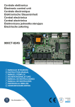
Centrale elettronica
Electronic control unit
Centrale électronique
Elektronische Steuereinheit
Central electrónica
Central electrónica
(OHNWURQLF]QDMHGQRVWNDVWHUXMąFD
Electrische zekering
kering
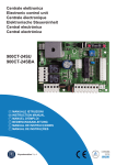
900CT-101
IT
GB
F
D
E
P
PL
NL
MANUALE ISTRUZIONI
INSTRUCTION MANUAL
MANUEL D'EMPLOI
BEDIENUNGSANLEITUNG
MANUAL DE INSTRUCCIONES
MANUAL DE INSTRUÇÕES
,16758.&-$2%6à8*,
GEBRUIKSHANDLEIDING
Key Automation S.p.A
ITALIANO
ATTENZIONE:
Leggere attentamente le istruzioni prima di eseguire l’installazione.
La non osservanza delle suddette istruzioni, l’uso improprio o un errore di collegamento potrebbe pregiudicare la sicurezza o il corretto funzionamento del dispositivo,
e quindi dell’intero impianto. Si declina ogni responsabilità per eventuali malfunzionamenti e/o danni dovuti derivanti dalla loro inosservanza.
ATTENZIONE:
Questo apparecchio non è destinato a essere usato da persone (Bambini compresi) le cui capacità
¿siche, sensoriali o mentali siano ridotte, oppure con mancanza di esperienza o di conoscenza, a
meno che esse abbiano potuto bene¿ciare, attraverso l’intermediazione di una persona responsabile della loro sicurezza, di una sorveglianza o di istruzioni riguardanti l’uso dell’apparecchio.
-I bambini devono essere sorvegliati per sincerarsi che non giochino con l’apparecchio
-Non permettere ai bambini di giocare con i comandi.
ATTENZIONE:
GOLLPSLDQWLHOHWWULFLHOHDXWRPD]LRQLGHYRQRHVVHUHHVHJXLWHGDSHUVRQDOHHVSHUWRHTXDOL¿FDWRQHO
rispetto delle norme di legge.
Tutti i collegamenti devono essere eseguiti con alimentazione di rete non presente.
COLLEGAMENTI ELETTRICI
Per garantire l’incolumità dell’operatore e per prevenire danni ai componenti, mentre si effettuano i
collegamenti, o si innesta la scheda radio, la centralina non deve essere assolutamente alimentata
elettricamente.
Per i cavi di alimentazione, linee motori, linea lampeggianti/luce di cortesia, elettroserratura utilizzare un cavo con sezione adeguata alla lunghezza del tragitto.(min 1,5 mmq).
Per le alimentazioni ausiliarie i comandi e i contatti di sicurezza una sezione minima di 0,5 mmq.
Quando i cavi di comando sono molto lunghi (oltre 30 m) è consigliabile il disaccoppiamento mediante dei relè presso la centralina stessa.
Nel caso di intervento di un fusibile, dopo aver rimosso la causa sostituirlo con un altro avente le
stesse caratteristiche.
Installare i vari dispositivi di sicurezza, ¿necorsa, fotocellule, costa sensibile, pulsante di stop.
Se uno o più dispositivi di sicurezza non vengono installati devono essere cortocircuitati i relativi
morsetti con il comune comandi.
Tutti i contatti N.C. Abbinati ad uno stesso ingresso devono essere collegati in serie.
Tutti i contatti N.A. Abbinati ad uno stesso ingresso devono essere collegati in parallelo.
Prevedere elementi di disconnessione dalla rete di alimentazione su posto accessibile.
Per l’alimentazione della centralina è previsto l’inserimento di un SEZIONATORE esterno (non in
dotazione) indipendente e correttamente dimensionato.
Prima di procedere all’attivazione del motore si chiede :
Sbloccare il motore meccanicamente e veri¿care l’esatto collegamento dei ¿necorsa in base all’apertura ed alla chiusura dell’anta, il led corrispondente al ¿necorsa interessato deve SPEGNERSI
con il ¿necorsa attivato
Chiudere manualmente l’anta, effettuare ora un impulso di P/P premendo il pulsante relativo la
prima manovra che deve effettuare l’anta è una APERTURA, se così non fosse togliere alimentazione all’impianto e girare il connettore JP4 MOTOR (N.19/20/21) in modo da invertire l’apre con il
chiude.
ATTENZIONE
I dati e le informazioni indicate in questo manuale sono da ritenersi suscettibili di modi¿ca in qualsiasi momento e senza obbligo di preavviso da parte di Key Automation S.r.l.
2
DATI TECNICI
ALIMENTAZIONE
CARICO MAX MOTORE
USCITA ALIMENTAZIONE ACCESSORI
TEMPO LAVORO
TEMPO PAUSA
TEMPERATURA DI FUNZIONAMENTO
CT-101
230Vac/50Hz
1200 W
24Vac 400mA
0-120sec
0-120sec
-20°C/+70°C
COLLEGAMENTI
4
14
9
25 26 27
7
21
20
19
3
4
5
6
7
8
9
10
11
12
13
14
15
15
11
6
5
13
12
1
2
22 23 24
10
1 2 3 4 5
1
.--.
8
6 7 8 9 10 11 12 13 14 15 16 17 18
2
3
DESCRIZIONE
CN1 Morsettiera collegamenti alimentazione 230Vac, lampeggiante e luce di cortesia
CN2 Morsettiera collegamento comandi e sicurezze
CN3 Morsettiera collegamento alimentazioni accessori 24Vac, secondo canale radio e antenna
CN4 Connettore per encoder
JP1 Connettore per scheda radio ricevente ad innesto
JP3 Connettore per condensatore
JP4 Morsettiera collegamento motore
JP5 Morsettiera collegamento ¿necorsa
LCD Display di segnalazione funzioni e ingressi di sicurezza
ENTER Pulsante per lo scorrimento funzioni per la programmazione P2
UP/DOWN Pulsante per variazione / regolazione settaggio funzioni P1( vedi tabella )
P/P Pulsante passo passo
F1 Fusibile protezione linea 230Vac 10A ritardato
F2 Fusibile protezione accessori 230Vac 315mA ritardato
FCC FCA Led di segnalazione dei ¿necorsa
3
ITALIANO
MODELLI E CARATTERISTICHE
900CT-101 con predisposizione per scheda radio.
La centrale di comando 900CT-101 è destinata al comando di un motore asincrono monofase utilizzato per automatizzare il movimento di uno scorrevole o di un basculante.
Ogni altro uso è improprio e vietato.
ITALIANO
CONNETTORE CN1
Morsettiera collegamenti alimentazione 230Vac, lampeggiante e luce di cortesia
1) N
Neutro 230Vac
2) F
Fase 230Vac
3) L.C.
Collegamento luce di cortesia max.25W 230Vac
4) COM LC/LP
Comune luce cortesia e lampeggiante ( in LC tempo ¿sso 2 min )
5) LMP
Collegamento lampeggiante max.25W 230Vac
Per la sostituzione della lampada del lampeggiante o la lampada di cortesia togliere l’alimentazione
dell’automazione;
1 2 3 4 5
6 7 8 9 10 11 12 13 14 15 16 17 18
Antenna
Lampeggiante
Luce
cortesia
230Vac
RG58
CONNETTORE CN2
Morsettiera collegamento comandi e sicurezze
6) $
Collegare la MESSA A TERRA dell’impianto
7) PED
Funzione Pedonale PED predisporre un contatto N.A. Normalmente Aperto
E’ un comando di apertura che nel caso sia attivato andrà ad aprire parzialmente l’anta.
8) P/P
Funzionamento Passo /Passo
Collegato tra il Mors.N.8 ed il Mors.N.12 Contatto N.A. Normalmente Aperto
Ingresso di comando Apre/Chiude o Apre/Stop/Chiude in base alla selezione del Parametro D
9) F1
Funzione Fotocellula Close
Collegata tra il Mors.N.9 ed il Mors. N.12 Contatto N.C. Normalmente Chiuso
Tale ingresso viene considerato una sicurezza, il contatto può essere interrotto in qualsiasi momento durante la
chiusura dell’automazione provocando l’immediato blocco del moto invertendo il senso di marcia
10) F2
Funzione Fotocellula Open
Collegata tra il Mors.N.10 ed il Mors.N.12 Contatto N.C. Normalmente Chiuso
Tale ingresso viene considerato una sicurezza, il contatto può essere interrotto in qualsiasi momento durante l’apertura dell’automazione provocando l’immediato blocco del moto, l’automazione continuerà l’apertura al ripristino
del contatto.
11) STP
Funzionamento Stop
Collegato tra il Mors. N.11 ed il Mors. N.12 Contatto Normalmente Chiuso N.C. Tale ingresso viene considerato una
sicurezza; il contatto può essere interrotto in qualsiasi momento bloccando immediatamente l’automazione disabilitando qualsiasi funzione compresa la Chiusura Automatica
12) COM
Comune dei collegamenti
1 2 3 4 5
6 7 8 9 10 11 12 13 14 15 16 17 18
-
24Vac/dc
+
1 2 3
F1
RX
24Vac/dc
- +
NA P/P
TX
NC
COMUNE
TX
RX
F2
1 2 3 4
-
24Vac/dc
24Vac/dc
- +
+
1 2 3
NC
1 2 3 4
NC STOP
4
Alim. accessori
Antenna
NA PED
ITALIANO
CONNETTORE CN3
Morsettiera collegamento alimentazioni accessori 24Vac, secondo canale radio e antenna
13)
Uscita 2° canale radio (solo se si utilizza ricevitore innesto 2 canali)
14)
Uscita 2° canale radio (solo se si utilizza ricevitore innesto 2 canali)
15)
Collegamento antenna (segnale)
16)
Collegamento antenna (calza di schermatura)
17)
Alimentazione accessori 24Vac Max 10 Watt
18)
Alimentazione accessori 24Vac Max 10 Watt
NO
1 2 3 4 5
6 7 8 9 10 11 12 13 14 15 16 17 18
Alim. accessori
Antenna
Uscita 2° canale
CONNETTORE JP3
Morsettiera collegamento condensatore
JP3 1)
Condensatore
JP3 2)
Condensatore
Motore
M
21
20
19
CONNETTORE JP4
Morsettiera collegamento motore
19)
Apertura motore
20)
Comune
21)
Chiusura motore
Condensatore
CONNETTORE CN4
Connettore collegamento encoder
25)
Segnale da encoder (nero)
26)
Positivo alim. encoder (marrone)
27)
Negativo alim. encoder (blu)
Morsettiera collegamento ¿necorsa
22)
Finecorsa chiusura NC
23)
Comune ¿necorsa
24)
Finecorsa apertura NC
NC Finecorsa APRE
CONNETTORE JP5
UNE
COMUNE
NC Finecorsa CHIUDE
25 26 27
22 23 24
N.%. i led corrispondenti ai ¿necorsa sono ACCESI quando non viene interessato il ¿necorsa relativo.
5
ITALIANO
DIAGNOSI VISIVA
La centrale di comando è stata progettata per automatizzare aperture residenziali ed industriali ad
1 motore con potenza massima di 1200W con controlli di sicurezza attivi e passivi per ottenere una
installazione conforme alle vigenti normative di sicurezza.
La grande af¿dabilità del sistema e l’alta concentrazione delle funzioni che vengono gestite da un
microcontrollore fanno si che il sistema possa calcolarsi tutti i parametri di rallentamento ed il tempo di lavoro autonomamente senza nessuna programmazione particolare da parte dell’installatore.
La centrale viene già fornita con una programmazione base che vi permette di avere già i parametri
fondamentali selezionati
L’ingresso STOP N°11 in cui è obbligatorio l’utilizzo di un contatto N.C. deve essere
chiuso e i due puntini del LCD NON devono lampeggiare, se lampeggiano vuol dire che il
contatto è aperto.
L’ingresso FOTO APRE F2 N°10 in cui è obbligatorio l’utilizzo di un contatto N.C. deve
essere chiuso e il puntino del LCD di sinistra F2OP deve essere SPENTO, se risultasse
ACCESO FISSO vuol dire che il contatto è aperto.
L’ingresso FOTO CHIUDE F1 N°9 in cui è obbligatorio l’utilizzo di un contatto N.C. deve
essere chiuso e il puntino del LCD di destra F1CL deve essere SPENTO, se risultasse
ACCESO FISSO vuol dire che il contatto è aperto.
N.B. I puntini del LCD in condizioni di normale utilizzo non devono ne lampeggiare ne essere accesi ¿ssi, si accendono o lampeggiano nel caso in cui intervenga la sicurezza corrispondente.
Con automazione chiusa visualizza.
led FCC spento FCA acceso
Durante l’APERTURA sul display si visualizza OP.
led FCC acceso FCA acceso
Se si è selezionato il funzionamento Automatico visualizza TC nel tempo di pausa.
led FCC acceso FCA spento
Durante la CHIUSURA sul display si visualizza CL.
led FCC acceso FCA acceso
Se si visualizza ST ( stop ) vuol dire che si è abilitata la funzione UOMO PRESENTE e
non si è terminato il ciclo di apertura o chiusura completa (parametro U1)
Tramite un nuovo comando di P/P veri¿care che si effettui l’apertura completa dell’anta sino al
¿necorsa, a questo punto ripremere il pulsante P/P e veri¿care la completa chiusura dell’anta sino
al ¿necorsa.
Dopo aver veri¿cato l’esatto funzionamento di apertura e chiusura completa
possiamo andare ad abilitare il rallentamento in base alla percentuale voluta
( parametro E ) e la Forza motore massima ( parametro L )
N.B. ad ogni variazione di qualsiasi parametro la centrale effettua, al primo impulso di start l’apprendimento del tempo di lavoro da cancello chiuso ad aperto tra i due ¿necorsa, solo dopo questa
manovra si potranno vedere i rallentamenti (se sono stati abilitati).
6
Si accede al menu dei parametri mantenendo premuto il pulsante ENTER (P2) ¿nchp appare il
primo parametro, premendo consecutivamente il pulsante ENTER (P2) si avanza con il menù parametri, per la variazione del parametro premere il pulsante Ľ UP/DO:N (P1)
N.B. Ogni variazione di funzione deve essere effettuata con l’automazione chiusa
FUNZIONI / VALORI
SENSIBILITÀ
--
Alta
Medio
Alta
Medio
Bassa
Bassa
CHIUSURA AUTOMATICA
(secondi)
NO
5
10
15
20
COMANDO PASSO PASSO
P/P
Apre
Stop
chiude
Apre
Chiude
% RALLENTAMENTO
NO
10%
Selezione rilevamento ostacoli attivo solo
con parametro L=0 e motore con sensore
ENCODER.
25
30
40
80
120
Modi¿cando il valore P/P si cambia il funzionamento dell’automazione
come descritto dalle funzioni si ricorda che la funzione Apre chiude
può essere critica per automazioni con grandi inerzie.
20%
30%
Attivando la funzione Rallentamento negli ultimi
secondi di funzionamento dell’automazione la
centrale comanda i motori a velocità ridotta in base
alla % scelta
ELETTROFRENO
NO
SI
Attivando la funzione Elettrofreno (se presente) tramite il parametro
F,si riesce a impedire che un cancello pesante,in seguito ad un comando o ad intervento di una sicurezza, a causa dell’inerzia continui il
movimento per qualche secondo invece di bloccarsi immediatamente
SELEZIONE TEMPO LAVORO MASSIMA (secondi)
90
180
Selezione tempo lavoro massima 90 sec / 180 sec
CONDOMINIALE
(SOLO APRE)
NO
SI
Attivando la funzione condominiale facciamo in modo che il primo
impulso di P/P apre ed accetta solo la riapertura durante la chiusura
FORZA MOTORE
100%
Max
10%
Min
CHIUDE DOPO TRANSITO
NO
SI
Attivando la funzione Chiude dopo Transito con chiusura automatica
inserita facciamo in modo che l’automazione si chiuda nel tempo più
breve possibile senza attendere la richiusura automatica
20%
30%
40%
50%
60%
70%
80%
90%
TIMER/SPIRA MAGNETICA
SU P/P
NO
SI
Attivando la funzione Timer / Spira magnetica, dopo aver terminato
l’apertura totale se si mantiene chiuso il contatto di P/P N.8 si blocca
il tempo di chiusura automatica in modo che il cancello non si chiuda
mai sino alla nuova apertura del contatto di P/P, nel caso intervenissero vari impulsi di P/P durante il tempo di attesa della chiusura automatica il tempo viene continuamente riazzerato
PARTENZA RALLENTATA
SOFT START
NO
SI
Attivando la funzione Soft Start nei primi secondi di movimento dell’automazione la centrale comanda il motore a velocità ridotta per avere
una partenza più dolce.
TIPOLOGIA MOTORE
--
Tipo 1
UOMO PRESENTE
NO
SI
PRELAMPEGGIO
NO
1sec
Tipo 2
Selezione tipologia rallentamento voluta
Attivando la funzione uomo presente tramite il parametro U si ha la
possibilità di far APRIRE l’automazione chiudendo il contatto di P/P
N.8 e far CHIUDERE l’automazione chiudendo il contatto PED N.7 al
rilascio dei due contatti l’automazione si posiziona in STOP
2sec
4sec
Attivando la funzione Prelampeggio prima di ogni
movimento il lampeggiante viene attivato per il
tempo selezionato
NB. Alla ¿ne della visualizzazione dei parametri si accede al contatore manovre totali che vengono
visualizzate in 2 videate differenti dove le migliaia si evidenziano con l’accensione del puntino:
Se si accende il puntino del LCD di sinistra vuol dire che sono state passate le 10.000 manovre
che andranno aggiunte al valore visualizzato.
Se si vuole azzerare tale contatore mantenere premuto assieme il pulsante P1 e P2 (ENTER/UPDO:N) ¿nchp non si visualizza 0.0 00
Per uscire dalla visualizzazione parametri premere il tasto ENTER pi volte ¿no a visualizzare la
condizione di automazione chiusa - - ( due trattini ).
7
ITALIANO
PROGRAMMAZIONE
ITALIANO
REGOLAZIONE FORZA MOTORI
Dopo uno spunto di 1,5 Secondi si inserisce il controllo di Forza elettronica in cui si parzializza la
tensione di alimentazione regolandone il valore tramite il parametro L.
N.B. riferirsi per i carichi di spinta massima alle normative vigenti.
ATTENZIONE:
dopo 3 rilevazioni d’ostacolo consecutive, il cancello si ferma in apertura e viene esclusa la chiusura automatica per riprendere il movimento bisogna premere il pulsante di comando o usare il
trasmettitore.
CONNETTORE RADIO
La centrale CT-101 è compatibile con i seguenti ricevitori Key Automation della serie MEMO ad
innesto: 900RXI-22 / 900RXI-42 / 900RXI-42R
AVVERTENZE FINALI
L’installazione dell’automazione deve essere eseguita a regola d’arte da personale quali¿cato
avente i requisiti di legge e fatta in conformità delle direttive vigenti.
Veri¿care la solidità delle strutture esistenti (colonne, cerniere, ante) in relazione alle forze sviluppate dal motore.
Veri¿care che vi siano dei fermi meccanici di adeguata robustezza a ¿ne apertura e ¿ne chiusura
delle ante.
Fare un’analisi dei rischi dell’automazione e di conseguenza adottare le sicurezze e le segnalazioni necessarie.
Installare i comandi (ad esempio il selettore a chiave) in modo che l’utilizzatore non si trovi in una
zona pericolosa.
Terminata l’installazione provare più volte i dispositivi di sicurezza, segnalazione e di sblocco
dell’automazione.
Applicare sull’automazione l’etichetta o la targhetta CE contenenti le informazioni di pericolo e i
dati di identi¿cazione.
Consegnare all’utilizzatore ¿nale le istruzioni d’uso, le avvertenze per la sicurezza e la dichiarazione CE di conformità.
Accertarsi che l’utilizzatore abbia compreso il corretto funzionamento automatico, manuale e di
emergenza dell’automazione.
Informare l’utilizzatore per iscritto (ad esempio nelle istruzioni d’uso) dell’ eventuale presenza di
rischi residui non protetti e dell’uso improprio prevedibile.
Predisporre un piano di manutenzione dell’impianto (almeno ogni 6 mesi per le sicurezze) riportando su di un apposito registro gli interventi eseguiti.
Conservare il presente manuale d’istruzioni per future consultazioni.
La ditta Key Automation S.r.l. si riserva la facoltà insindacabile di apportare, in qualsiasi momento,
le modi¿che che si rendessero necessarie ai ¿ni di un miglioramento estetico e/o funzionale.
SMALTIMENTO
Questo prodotto è formato da vari componenti che potrebbero a loro volta contenere
sostanze inquinanti. Informarsi sul sistema di riciclaggio o smaltimento del prodotto attenendosi alle norme di legge vigenti a livello locale.
NON DISPERDERE NELL’AMBIENTE!
8
NOTE
NOTES
NOTES
ANMERKUNGEN
NOTA
OBSERVAÇÕES
WARNING:
ENGLISH
It is advisable to read the instructions carefully before you start installation.
Failure to comply with these instructions, improper use or incorrect connection may compromise
the safety or correct operation of the device and hence of the entire system.
No liability shall be accepted for any malfunctions and/or damage due to failure to comply with the
instructions.
The company reserves the right to make improvements to the products.
THIS BOOKLET IS TO BE USED ONLY BY THE INSTALLER
Installation must be carried out only by professionally quali¿ed personnel in compliance with current legal requirements.
ELECTRICAL CONNECTIONS
To ensure operator safety and to prevent damage to the components while connections are being
made, or when the radio card is being inserted, the control unit absolutely must not be powered on.
For power cords, motor lines, Àasher/courtesy light line, and electric locN, use a cable with a crosssection that is suitable for the length (minimum 1.5 mm2).
For auxiliary power supplies, controls and safety contacts a minimum section of 0,5 mm2. When
the control cables are very long (more than 30 m), de-coupling is suggested using relays at the
control unit.
If a fuse trips, after removing the cause, replace it with another one of the same type. Install the
various safety devices, limit switches, photocells, sensitive rib, stop button.
If one or more of the safety devices are not installed, the corresponding terminals must be short
circuited with the controls common.
All contacts N.C. Assigned to the same input must be connected in series.
All contacts N.O. Assigned to the same input must be connected in parallel.
Provide disconnecting devices in the power supply networN in accessible places.
For the power supply of the control unit, there must be an external disconnecting switch (not included), independent and properly sized.
10
MODELS AND CHARACTERISTICS
TECHNICAL DATA
POWER SUPPLY
MAX. MOTOR LOAD
ACCESSORIES POWER SUPPLY OUTPUT
WORKING TIME
PAUSE TIME
OPERATING TEMPERATURE
ENGLISH
900CT-101 Control unit for 1 230 Vac motor sliding or overhead motor, set up for radio card.
CT-101
230Vac/50Hz
1200 W
24Vac 400mA
0-120sec
0-120sec
-20°C/+70°C
DESCRIPTION
4
14
9
25 26 27
7
.--.
21
20
19
8
22 23 24
15
11
10
6
5
13
12
1 2 3 4 5
1
6 7 8 9 10 11 12 13 14 15 16 17 18
2
3
DESCRIPTION
CN1 230Vac power supply terminal board, Àasher and courtesy light
2 CN2 Controls and safeties connection terminal board
3 CN3 Terminal board for connection of 24Vac accessories second radio channel and antenna
4 CN4 encoder
5 JP1 Connector for snap-in radio receiving card
6 JP3 Connector for capacitor
7 JP4 Motor connection terminal board
8 JP5 Limit switch connection terminal board
9 LCD Display for signalling functions and safety inputs
10 ENTER button for scrolling programming functions
11 UP/DOWN button for function settings (see table)
12 P/P Step/step button
13 F1 line protection 230Vac 10A delayed
14 F2 accessory line protection 230Vac 315mA delayed
15 FCC FCA Led limit switch
11
1
CN1
ENGLISH
dedicated to the connection of the power supply of the board:
1) N
230Vac
2) F
230Vac
3) L.C.
Courtesy light max.25W 230Vac
4) COM LC/LP
Shared courtesy light or Àasher
5) LMP
Connected to the Àasher max.25W 230Vac
1 2 3 4 5
6 7 8 9 10 11 12 13 14 15 16 17 18
230Vac
RG58
CN2
6) $
7) PED
Connected to the earth of the system
Pedestrian function Contact N.O. Normally open
It is an opening command which when activated will partially open the door.
8) P/P
Step/step operation
Connected between Term. N.8 and Term. N.12 Contact N.O
Control input open/close or open/stop/close based on selection of parameter D
9) F1
Photocell Close Function
Connected between Term. N.9 and Term. N.12 Contact N.C.Normally Closed
This input is considered a safety, the contact can be interrupted at any time during closing of the automation causing an immediate stop in movement and reversing the direction of movement
10) F2
Photocell Open Function
Connected between Term. N.10 and Term. N.12 Contact N.C. Normally closed
This input is considered a safety, the contact can be interrupted at any time during opening by the automation causing an immediate stop in movement, the automation will continue until the contact is restored.
11) STP
Stop function
Connected to Term. N.11 and Term. N.12 Contact Normally Closed N.C. This input is considered a safety the contact can be interrupted at any time immediately stopping the automation disabling any function including automatic
closing.
12) COM
1 2 3 4 5
6 7 8 9 10 11 12 13 14 15 16 17 18
-
24Vac/dc
+
1 2 3
F1
RX
24Vac/dc
- +
NA P/P
TX
NC
COMUNE
TX
RX
F2
1 2 3 4
-
24Vac/dc
24Vac/dc
- +
+
1 2 3
NC
1 2 3 4
NC STOP
12
Alim. accessori
Antenna
NA PED
Accessory power supply connection 24Vac 15 watts max
13)
2nd radio channel connection (only if using 2-channel radio connector)
14)
2nd radio channel connection (only if using 2-channel radio connector)
15)
Antenna connection (signal)
16)
Antenna connection (mesh)
17)
24Vac Max 10 Watt
18)
24Vac Max 10 Watt
NO
1 2 3 4 5
6 7 8 9 10 11 12 13 14 15 16 17 18
JP3
JP3 1)
JP3 2)
Capacitor
Capacitor
M
JP4
21
20
19
Connection of Motor
19)
opening
20)
shared
21)
closing
CN4
25)
26)
27)
Signal encoder
Supply encoder
Negative encoder
25 26 27
JP5
Motor limit switch connection
22)
limit switch closing NC
23)
common connection
24)
limit switch opening NC
22 23 24
N.B. The LEDs that correspond to the limit switches are ON when the relative limit switch is not involved.
13
ENGLISH
CN3
VISUAL DIAGNOSIS
The control unit is designed to automate residential and industrial openings with 1 motor having a
maximum power of 1200W with active and passive safety controls for installation that is compliant
with current safety standards.
ENGLISH
The great reliability of the system and the high concentration of the functions are managed by a
micro-controller so that the system can autonomously calculate all deceleration parameters and the
worNing time with no special programming by the installer.
STOP input no. 11 in which the use of a contact N.C. is compulsory must be closed and
the two points of the LCD must not Àash. If they Àash, it means that the contact is open
The input PHOTO OPEN F2 no. 10, which requires the use of an NC contact, must
be closed and the F2OP point of the LCD on the left must be OFF. If it is on STEADY it
means that the contact is open
The input PHOTO OPEN F1 no. 9, which requires the use of an NC contact, must be
closed and the F1CL point of the LCD on the right must be OFF. If it is on STEADY it
means that the contact is open
N.B. In normal use, the points of the LCD must not Àash or be on steady. They Àash or stay on if
the corresponding safety is activated.
With the automation closed, will be shown
During OPENING the display will show OP
If you have selected Automatic operation, TC will be shown in the pause time
During CLOSING the display will show CL
If ST (stop) is shown, it means that the DEAD MAN function is enabled and the complete opening or closing cycle has not ended
By using a new P/P command checN that the complete opening of the door is carried out up to the
stop. At this point press the P/P button again and checN the complete closing of the door up to the
stop.
After having veri¿ed the correct complete opening and closing enable the
deceleration based on the desired percentage ( Par. E ) and the maximum
motor force ( Par.L )
N.B. with each variation of any parameter the control unit will, at the ¿rst start impulse, verify the
working time of the closed and open gate between the two stops. Only once this is carried out the
enabling of the deceleration can be veri¿ed
14
PROGRAMMING FUNCTIONS
FUNCTIONS/VALUES
SENSITIVITY
--
High
Medium
High
Medium
Low
Low
AUTOMATIC CLOSURE
(seconds)
NO
5
10
15
20
STEP BY STEP COMMAND
P/P
Open
Stop
close
Open
Close
By activating the step/step function, you avoid passage of the automation in the stop state. The enabled function may be critical for automations with high inertia.
10%
When the deceleration function is activated in the
last seconds of operation of the automation, the
control unit slows the motors based on the selected
%.
% DECELERATION
NO
20%
30%
Obstacle detection activated with L=0 and
motor with ENCODER sensor
25
30
40
80
120
ELECTROBRAKE
NO
YES
By activating the electrobraNe function through the F parameter, a
heavy gate is prevented from continuing its movement, due to its inertia, for a few seconds instead of stopping it instantenously following a
command or a safety action
MAXIMUM WORKING TIME
EXTENSION
(expressed in seconds)
90
180
Maximum worNing time extention 90/180 seconds
CONDOMINIUM
(OPEN ONLY)
NO
YES
Activate the condominium function so that the ¿rst step/step impulse
opens and accepts only re-opening during closing
MOTOR FORCE
100%
Max
10%
Min
20%
CLOSE AFTER TRANSIT
NO
YES
When you activate the Close After Transit function with automatic closure activated, the automation is closed in the shortest time possible
without waiting for automatic re-closing.
30%
40%
50%
60%
70%
80%
90%
TIMER/MAGNETIC COIL
ON STEP/STEP
NO
YES
When you activate the function Timer / Magnetic Coil via parameter P
after terminating total opening if step/step contact N.8 is Nept closed
the automatic closing time is locNed so that the gate never closes until
the step/step contact is opened again, if there are several step/step
impulses during the standby time for automatic closing the time will be
continuously reset
SOFT START DELAYED
START TIME
NO
YES
When you activate the Soft Start function, during the ¿rst seconds of
movement of the automation the control unit Neeps the motor at reduced speed for a softer start.
MOTOR TYPE
--
Type 1
DEAD MAN
NO
YES
PRE-FLASHING
NO
1sec
Type 2
Select the desired type of slowdown
When you activate the Man Present function via parameter U, you can
open the automation until step/step contact N.8 is closed and close the
automation until contact PED n.7 is closed when the two contacts are
released the automation goes to STOP position.
2sec
4sec
When the pre-Àashing function is activated, before
any movement the Àasher is activated for the
selected time
N.B.:Once the parameters have been displayed, the total manoeuvres counter are shown in two
different screens, where the thousand units are indicated by the lighting up of the point. To reset
this counter, simultaneously press and hold buttons P1 and P2 (ENTER/UP-DOWN) until 0000 is
displayed
N.B. If the point of the LCD on the left lights up, it means that 10,000 manoeuvres have been exceeded, which must be added to the value shown.
To exit parameter display, press ENTER several times until automatic closure condition is shown
(- - two dashes).
15
ENGLISH
Access the parameter menu by holding the ENTER button until the ¿rst parameter, appears. Press
the ENTER button (P2) repeatedly to advance through the parameters menu. To change the parameter press Ľ UP/DOWN (P1)
N.B. any variation in function must be made with the automation closed
ADJUSTMENT OF MOTOR FORCE
After a breakaway of 1,5 seconds, the electronic force control activates which distributes the power
supply, adjusting the value by means of parameter L.
N.B. for maximum thrust loads refer to current standards.
ENGLISH
RADIO CONNECTOR
The CT-101 control unit is compatible with the following Key Automation receivers of the MEMO
snap-in series: 900RXI-22 / 900RXI-42 / 900RXI-42R
FINAL WARNINGS
The installation of the automation must be performed properly by quali¿ed personnel in possession of legal requirements and in compliance with machine directive.
ChecN the solidity of existing structures (columns, hinges, doors) in relation to the force generated
by the motor.
ChecN that there are suitably sturdy mechanical stops at the end of opening and closing travel of
the doors.
Analyze the risNs of the automation and adopt necessary safety measures and warnings.
install controls (such as the Ney selector) so that the user is not in a hazardous position.
Upon completion of installation, checN the safety devices several times, as well as those for signalling and automation release.
Provide the automation with the EC label or tag that contains the danger information and identi¿cation data.
Give the ¿nal user the instructions for use, safety warnings and the EC declaration of conformity.
MaNe sure the user understands proper automatic, manual and emergency operation of the automation.
Inform the user in writing (for example in the instructions for use) of any unprotected residual risNs
and foreseeable improper use.
Provide a maintenance schedule for the system (at least every 6 months for the safeties) with an
appropriate register of worN performed.
Keep this instruction manual for future reference.
Key Automation S.r.l. reserves the right to maNe, at any time, any modi¿cations which may be
required to improve appearance and/or operation.
DISPOSAL
This product is composed of various components which may in turn contain pollutants.
Do not dispose of it in the environment! Find out about the method for recycling or disposing of the product in compliance with current local laws
16
NOTE
NOTES
NOTES
ANMERKUNGEN
NOTA
OBSERVAÇÕES
ATTENTION :
Lire attentivement les instructions avant de procpder à l’installation.
Le non-respect des instructions susmentionnpes, toute utilisation impropre ou toute
erreur de branchement peut nuire à la spcuritp ou au bon fonctionnement du dispositif et, par conspquent, à toute l’installation.
Nous dpclinons toute responsabilitp en cas de mauvais fonctionnement et/ou de
dommages dprivant du non-respect des instructions.
La sociptp se rpserve le droit d’apporter toute modi¿cation visant à ampliorer ses
produits.
FRANÇAIS
CE MANUEL EST EXCLUSIVEMENT DESTINÉ À L’INSTALLATEUR
L’installation ne doit rtre effectupe que par des techniciens quali¿ps et dans le respect des dispositions lpgales en vigueur.
BRANCHEMENTS ÉLECTRIQUES
Pour garantir la sécurité de l’opérateur et prévenir tout risque d’endommagement des composants,
la centrale doit impérativement être débranchée de l’alimentation électrique pendant les opérations
de connexion et d’installation de la carte radio.
Pour les câbles d’alimentation, lignes moteurs, ligne clignotants/éclairage de courtoisie, serrure
électrique, utiliser un câble ayant une section adéquate à la longueur du parcours (1,5 mm2 minimum).
Pour les alimentations auxiliaires, les commandes et les contacts de sécurité, le câble doit avoir
une section minimale de 0,5 mm2. Lorsque les câbles de commande sont très longs (plus de 30
m), un découplage par relais dans la centrale même est recommandé.
Si un fusible saute, le remplacer par un fusible ayant les mêmes caractéristiques après avoir éliminer la cause du court-circuit. Monter les différents dispositifs de sécurité, les butées de ¿n de
course, les cellules photoélectriques, les barres palpeuses, le bouton d’arrêt.
Si un ou plusieurs dispositifs de sécurité ne sont pas installés, court-circuiter les bornes y afférentes en utilisant la commande habituelle.
Tous les contacts N.F. associés à une même entrée doivent être reliés en série.
Tous les contacts N.O. associés à une même entrée doivent être reliés en parallèle.
Prévoir la pose d’éléments de déconnexion sur le réseau d’alimentation électrique directement
accessible sur place.
L’alimentation de la centrale prévoit la pose d’un SECTIONNEUR externe indépendant (non fourni), dimensionné comme il se doit.
18
MODÈLES ET CARACTÉRISTIQUES
900CT-101 Centrale de commande pour 1 moteur 230 Vac pour portail coulissant ou basculant,
prédisposition pour carte radio
CT-101
230Vac/50Hz
1200 W
24Vac 400mA
0-120sec
0-120sec
-20°C/+70°C
FRANÇAIS
CARACTÉRISTIQUES TECHNIQUES
ALIMENTATION
PUISSANCE MAX. MOTEUR
SORTIE ALIMENTATION AUXILIAIRES
DURÉE MOUVEMENT
DURÉE PAUSE
TEMPÉRATURE DE FONCTIONNEMENT
DESCRIPTION
4
14
9
25 26 27
7
.--.
21
20
19
8
22 23 24
15
11
10
6
5
13
12
1 2 3 4 5
1
6 7 8 9 10 11 12 13 14 15 16 17 18
2
3
DESCRIPTION
CN1 Barrette de connexion alimentation 230Vac, clignotante et veilleuse
2 CN2 Barrette de connexion des commandes et des dispositifs de sécurité
3 CN3 Connexion alimentation des auxiliaires 24Vac, en fonction du canal radio et de l’antenne
4 CN4 Encoder
5 JP1 Connecteur pour la carte radio du récepteur embrochable
6 JP3 Connecteur pour condenseur
7 JP4 Barrette de connexion du moteur
8 JP5 Barrette de connexion du ¿n de course
9 LCD Af¿cheur de signalisation des fonctions et des entrées de sécurité
10 ENTER Touche pour le dé¿lement des fonctions pour la programmation
11 UP/DOWN Touche pour la variation/réglage de la con¿guration des fonctions ( voir tableau )
12 P/P Bouton pas-à-pas
13 F1 Fusible protection de la ligne 230Vac 10A retardé
14 F2 Fusible protection de la ligne auxiliaires 230Vac 315mA retardé
15 FCC FCA Led du ¿n de course
19
1
CN1
Destiné à la connexion des alimentations de la carte
1) N
230Vac
2) F
230Vac
3) L.C.
Relié à la lumière de courtoisie max.25W 230Vac
4) COM LC/LP
Commun à la lumière de courtoisie ou à la lampe clignotante
5) LMP
Relié à la lampe clignotante max.25W 230Vac
1 2 3 4 5
6 7 8 9 10 11 12 13 14 15 16 17 18
FRANÇAIS
230Vac
RG58
CN2
6) $
7) PED
Sert à relier l’installation à la terre
Fonction Passage piéton
Relipe entre la borne N et la borne N 12 Contact N.O. Normalement ouvert
8) P/P
Fonctionnement Pas-à-Pas
CConnectp entre la borne N 8 et la borne N12 Contact N.O. Normalement ouvert
Entrpe de commande Ouvrir/Fermer ou Ouvrir/Stop/Fermer en fonction de la splection du paramqtre D
9) F1
Fonction Photocellule Close
Raccordpe entre la borne N 9 et la borne N 12 Contact N.F. Normalement fermp
Cette entrpe est considprpe comme une spcuritp, le contact peut rtre coupp à tout moment pendant la fermeture
de l’automatisme, ce qui entravne le blocage instantanp du mouvement et inverse le sens de marche.
10) F2
Fonction Photocellule Open
Connectpe entre la borne N 10 et la borne N 12 Contact N.F. Normalement fermp
Cette entrpe est considprpe comme une spcuritp, le contact peut rtre coupp à tout moment pendant l’ouverture de
l’automatisme, ce qui entravne le blocage instantanp du mouvement, l’automatisme continuera l’ouverture dqs que
le contact sera rptabli
11) STP
Fonctionnement Stop
Connectp entre la borne N 11 et la borne N 12 Contact normalement fermp N.F. Cette entrpe est considprpe
comme une spcuritp, le contact peut rtre coupp à tout moment ce qui entravne le blocage instantanp de l’automatisme en dpsactivant toute fonction, y compris la fermeture automatique
12) COM
1 2 3 4 5
6 7 8 9 10 11 12 13 14 15 16 17 18
-
24Vac/dc
+
1 2 3
F1
RX
24Vac/dc
- +
NA P/P
TX
NC
COMUNE
TX
RX
F2
1 2 3 4
-
24Vac/dc
24Vac/dc
- +
+
1 2 3
NC
1 2 3 4
NC STOP
20
Alim. accessori
Antenna
NA PED
CN3
Connexion 2e canal radio (seulement si l’on utilise un récepteur embrochable 2 canaux)
Connexion 2e canal radio (seulement si l’on utilise un récepteur embrochable 2 canaux)
Branchement antenne
Branchement antenne
24Vac Max 10 Watt
24Vac Max 10 Watt
NO
1 2 3 4 5
6 7 8 9 10 11 12 13 14 15 16 17 18
FRANÇAIS
13)
14)
15)
16)
17)
18)
JP3
JP3 1)
JP3 2)
Condensateur
Condensateur
M
21
20
19
JP4
Branchement du moteur
19)
ouverture
20)
communes
21)
fermeture
CN4
25)
26)
27)
encoder
encoder
encoder
25 26 27
JP5
Raccordement ¿n de course moteur entre
22)
Fin de course fermeture
23)
Raccordement commun ¿n de course moteurs
24)
Fin de course ouverture
22 23 24
N.B. les DEL correspondant aux ¿ns de course sont ALLUMeES quand le ¿n de course y affprent
n’est pas concernp
21
DIAGNOSTIC VISUEL
La centrale de commande a été conçue pour automatiser l’ouverture de portails résidentiels et
industriels, avec 1 moteur puissance maximale 1200W. avec contrôles de sécurité actifs et passifs
pour répondre aux normes de sécurité en vigueur.
La grande ¿abilité du système et la haute concentration des fonctions gérées par un microcontrôleur permettent au système de calculer de façon autonome tous les paramètres de ralentissement
et la durée de mouvement sans que l’installateur doive programmer quoi que ce soit.
L’entrée STOP n° 11 qui requiert obligatoirement un contact NF. doit être fermée et
les deux points de l’LCD NE doivent PAS clignoter s’ils clignotent, cela signi¿e que le
contact est ouvert
FRANÇAIS
L’entrée PHOTO OUVRIR F2 n° 10 qui requiert obligatoirement un contact N.F. doit être
fermée et le point de l’LCD à gauche F2OP doit être ÉTEINT s’il s’avérait ALLUMÉ FIXE,
cela signi¿erait que le contact est ouvert.
L’entrée PHOTO FERMER F1 n° 9 qui requiert obligatoirement un contact N.f. doit être
fermée et le point de l’LCD à droite F1CL doit être ÉTEINT s’il s’avérait ALLUMÉ FIXE,
cela signi¿erait que le contact est ouvert.
N.B. Dans des conditions normales d’utilisation, les tirets de l’LCD ne doivent pas clignoter ni être
allumés de façon ¿xe. Ils s’allument ou clignotent lorsque le dispositif de sécurité y afférent se
déclenche.
Avec l’automatisme fermé, l’écran af¿che
Pendant l’OUVERTURE, OP s’af¿che sur l’écran
Si vous avez sélectionné le fonctionnement automatique, l’écran af¿che TC pendant le
temps de pause
Pendant la FERMETURE, CL s’af¿che sur l’écran
Si ST ( STOP ) s’af¿che, cela signi¿e que la fonction DÉTECTEUR DE PRÉSENCE a
été activée et que le cycle d’ouverture ou de fermeture ne s’est pas complètement terminé
En actionnant de nouveau la commande P/P, véri¿er si le vantail s’ouvre complètement Musqu’à la
butée de ¿n de course et à ce point, appuyer de nouveau sur la touche P/P et véri¿er si le vantail
se ferme complètement Musqu’à la butée de ¿n de course
Après avoir véri¿é que le vantail s’ouvre et se ferme bien complètement,
vous pouvez activer la fonction de ralentissement en fonction de l’intermittence de fonctionnement désirée ( § E ) et la force moteur maximale (§ L )
N.B. à chaque variation d’un paramqtre quelconque, et à la premiqre commande de marche, la
centrale effectue un apprentissage de la durpe du mouvement de portail fermp à portail ouvert
jusqu’aux deux butpes de ¿n de course et ce n’est qu’aprqs cette man°uvre qu’il est possible de
voir si le ralentissement a ptp activp.
22
FONCTIONS DE PROGRAMMATION
Pour accpder au menu des paramqtres, maintenir la touche ENTER enfoncpe jusqu’à ce que le
premier paramqtre, le paramqtre, apparaisse ; appuyer plusieurs fois de suite sur la touche ENTER
(P2) pour se dpplacer dans le menu des paramqtres ; pour modi¿er un paramqtre, appuyer sur la
touche Ľ UP/DOWN (P1)
N.B. toute modi¿cation de fonction doit rtre effectupe quand l’automatisme est fermp
FONCTIONS / VALEURS
--
haute
Moyenne
-haute
Moyenne basse
basse
FERMETURE AUTOMATIQUE (secondes)
NON
5
10
15
20
COMMANDE PAS-À-PAS
P/P
Ouvrir
Stop
Fermer
Ouvrir /
Fermer
% RALLENTISSEMENT
NON
10%
Sélection détection obstacle activée avec
paramètre L = 0 et moteur avec senseur
d’ ENCODEUR
25
30
40
80
120
En activant la fonction P/P, on évite que l’automatisme ne passe à l'état
de Stop rappelons que la fonction activée peut s'avérer critique pour
les automatismes à grandes inerties
20%
30%
En activant la fonction Ralentissement pendant les
dernières secondes de fonctionnement de l’automatisme, la centrale commande les moteurs à une
vitesse réduite en fonction du % sélectionné.
ÉLECTROFREIN
NON
OUI
Activer la fonction Électrofrein au moyen du paramètre F, sert à empêcher
qu'un portail lourd, suite à une commande ou au déclenchement d'un dispositif de sécurité, continue sa course pendant quelques secondes à cause de
la force d'inertie, au lieu de se bloquer instantanément.
EXTENSION MAXIMALE
DU TEMPS DE TRAVAIL
(en seconds)
90
180
Sélection de l’extension du temps de travail à max 90/180 seconds.
COPROPRIÉTÉ
(OUVRIR SEULEMENT)
NON
OUI
Activer la fonction Copropriété, pour que la première commande P/P
ouvre et n'accepte que la réouverture pendant la fermeture
FORCE MOTEUR
100 %
max.
10 %
min.
FERMER APRÈS
PASSAGE
NON
OUI
Activer la fonction Fermer après le passage avec fermeture automatique activée, pour que l’automatisme ferme le plus vite possible sans
attendre la re-fermeture automatique.
20%
30%
40%
50%
60%
70%
80%
90%
MINUTEUR/SPIRE MAGNÉTIQUE SUR P/P
NON
OUI
En activant la fonction Minuteur/Spire magnétique au moyen du paramètre P après avoir terminé l’ouverture totale, en laissant le contact
P/P N. 8 fermé, on bloque le temps de fermeture automatique pour que
le portail ne se ferme pas tant que le contact P/P n'a pas été rouvert si
plusieurs commandes P/P interviennent pendant le temps de pause de
la fermeture automatique, le temps est constamment remis à zéro.
MISE EN MARCHE PROGRESSIVE
SOFT START
NON
OUI
En activant la fonction Soft Start, dans les premières secondes de mouvement de l’automatisme, la centrale commande le moteur à vitesse
réduite pour une mise en marche plus douce
--
Type 1
TYPE DE MOTEUR
DÉTECTEUR DE
PRÉSENCE
NON
OUI
PRÉ-CLIGNOTEMENT
NON
1s
Type 2
Sélectionnez le type de ralentissement
En activant la fonction Détecteur de présence au moyen du paramètre U, il est
possible de faire ouvrir l’automatisme tant que le contact P/P N. 8 est fermé et
de faire fermer l’automatisme tant que le contact PED N. 7 est fermé lorsque
les deux contacts se détendent, l’automatisme se positionne sur STOP
2s
4s
En activant la fonction Pré-clignotement, le clignotant s'allume avant toute ouverture ou fermeture
pendant une durée programmée.
NB. ¬ la fin de la visualisation des paramqtres, on accqde au compteur du total des man°uvres qui sont affichpes
sur 2 pages-pcran diffprentes où les milliers sont indiqups par le point qui s’allume : pour remettre ce compteur à zpro,
appuyer simultanpment sur les touches P1 et P2 (ENTER/UP-DOWN) jusqu’à ce que 0000 s’affiche.
N.B. Si le point du LCD de gauche s’allume, cela signifie qu’on a dppassp les 10 000 man°uvres et qu’elles devront
rtre ajouter à la valeur affichpe.
Pour quitter l’affichage des paramqtres, appuyer plusieurs fois sur la touche ENTER jusqu’à ce que l’ptat d’automatisme fermp - - ( deux tirets ) s’affiche.
23
FRANÇAIS
SENSIBILITE’
RÉGLAGE DE LA FORCE DES MOTEURS
Aprqs une pointe de dpmarrage de 1,5 s. insprer le contr{le plectronique de la Force qui permet de
dpcouper la tension d’alimentation en en rpglant la valeur au moyen du paramqtre L
N.B. pour les puissances de pousspe maximale, se rpfprer aux normes en vigueur
CONNECTEUR RADIO
FRANÇAIS
La centrale CT-101 est compatible avec les récepteurs embrochables Key Automation série MEMO
ci-dessous : 900RXI-22 / 900RXI-42 / 900RXI-42R
DERNIÈRES RECOMMANDATIONS
L’automatisme doit être installé dans les règles de l’art, par du personnel quali¿é ayant une formation reconnue par la loi et dans le respect de la directive machines
Véri¿er la solidité des structures existantes (piliers, gonds, vantaux) en fonction des forces développées par le moteur.
Contrôler si des butées mécaniques d’une robustesse adéquate sont montées en ¿n d’ouverture
et de fermeture des vantaux.
Faire une analyse des risques de l’automatisme et adopter les mesures de sécurité et les signalisations qui s’imposent.
Installer les commandes (par exemple le sélecteur à clé) de sorte que l’utilisateur ne se trouve
pas dans une zone à risque.
Une fois l’installation terminée, tester plusieurs fois les dispositifs de sécurité, de signalisation et
de déblocage de l’automatisme.
Apposer sur l’automatisme l’étiquette ou la plaque CE avec les avis de danger et les données
signalétiques.
Remettre à l’utilisateur ¿nal, le mode d’emploi, les recommandations de sécurité et la déclaration
CE de conformité.
Véri¿er si l’utilisateur a bien compris le fonctionnement automatique, manuel et de secours de
l’automatisme.
S’il y a lieu, informer l’utilisateur par écrit (par exemple dans le mode d’emploi) des risques résiduels ne pouvant pas être supprimés et le mettre en garde contre toute mauvaise utilisation du
produit.
Préparer un plan de maintenance de l’installation (au moins tous les six mois pour les dispositifs
de sécurité) en inscrivant les interventions effectuées sur un registre.
Conserver le présent manuel pour pouvoir le consulter par la suite.
La société Key Automation S.r.l. se réserve le droit d’apporter, à tout moment, les modi¿cations
qui s’avèreront nécessaires pour l’amélioration des caractéristiques esthétiques et/ou fonctionnelles de ses produits.
MISE AU REBUT
Ce produit se compose de divers éléments susceptibles à leur tour de contenir des
substances polluantes. Ne pas Meter dans la nature ! Se renseigner sur le système
de recyclage ou d’élimination du produit et respecter les réglementations locales en
vigueur.
24
NOTE
NOTES
NOTES
ANMERKUNGEN
NOTA
OBSERVAÇÕES
ACHTUNG:
Bevor Sie mit der Installation beginnen, lesen Sie die Bedienungsanleitung aufmerksam durch.
Die Nichtbeachtung der oben aufgeführten Anweisungen, unsachgemäßer Gebrauch
oder Anschlussfehler können die Sicherheit bzw. den einwandfreien Betrieb des Geräts und folglich der gesamten Anlage beeinträchtigen.
Für Betriebsstörungen und/oder Schäden, die aus der Nichtbeachtung der Anweisungen entstehen, wird keinerlei Haftung übernommen.
Die Firma behält sich das Recht vor, Änderungen zur Verbesserung des Produkts
vorzunehmen.
DIESES HANDBUCH IST NUR FÜR DEN INSTALLATEUR BESTIMMT
Die Installation darf nur von quali¿ziertem Fachpersonal gemäß der vom geltenden Gesetz vorgesehenen Bestimmungen ausgeführt werden.
ELEKTRISCHE ANSCHLÜSSE
DEUTSCH
Die Steuereinheit darf zum Schutz des Bedieners auf Neinen Fall unter Spannung stehen, wlhrend
die Anschlsse vorgenommen werden oder die FunNplatine eingesetzt wird.
Fr die VersorgungsNabel, Motorenleitungen, BlinNlicht-/Begrungslichtleitung und EleNtroschloss
ein Kabel mit einem der Llnge des Verlaufs angepassten Querschnitt verwenden (min. 1,5 qmm).
Fr die Hilfsspeisungen die Steuerungen und die SicherheitsNontaNte einen Mindestquerschnitt von
0,5 qmm. Wenn die SteuerNabel sehr lang sind (ber 30 m) emp¿ehlt sich eine EntNopplung ber
die Relais der Steuereinheit.
Bei Ausl|sung einer Sicherung die Ursache beseitigen und mit einer neuen, die die gleichen MerNmale aufweist, austauschen. Die einzelnen Sicherheitsvorrichtungen wie Endschalter, LichtschranNen, Sicherheitsleiste und Stopp-Taste installieren.
Falls eine oder mehrere Sicherheitsvorrichtungen nicht installiert werden, müssen die entsprechenden Klemmen mit der allgemeinen Steuerung Nurzgeschlossen werden.
Alle NC - KontaNte Geh|ren sie zum gleichen Eingang müssen sie in Serie angeschlossen werden.
Alle NO - KontaNte Geh|ren sie zum gleichen Eingang müssen sie parallel angeschlossen werden.
An einer erreichbaren Stelle im Versorgungsnetz Abtrennelemente vorsehen.
Für die Versorgung der Steuereinheit ist die Zwischenschaltung eines externen TRENNSCHALTERS vorgesehen (wird nicht mitgeliefert), der unabhlngig ist und richtig bemessen sein muss.
26
MODELLE UND MERKMALE
900CT-101 Steuereinheit für 1 Motor 230Vac für Motor Schiebe- oder Schwenktore,
Vorrüstung für Funkplatine
TECHNISCHE DATEN
SPEISUNG
MAX MOTORLAST
VERSORGUNGSAUSGANG ZUBEHÖR
ARBEITSZEIT
PAUSENZEIT
BETRIEBSTEMPERATUR
CT-101
230Vac/50Hz
1200 W
24Vac 400mA
0-120sec
0-120sec
-20°C/+70°C
BESCHREIBUNG
14
9
25 26 27
7
.--.
21
20
19
8
22 23 24
15
11
10
6
5
13
12
1 2 3 4 5
1
6 7 8 9 10 11 12 13 14 15 16 17 18
2
3
BESCHREIBUNG
CN1 Klemmleiste Anschlüsse Speisung 230Vac, BlinNlicht und Begrüungslicht
2 CN2 Klemmleiste Anschluss Steuerungen und Sicherheitsvorrichtungen
3 CN3 Anschluss Speisung Zubeh|r 24Vac, zweiter FunNNanal und Antenne
4 CN4 Encoder
5 JP1 Verbinder für FunNempfangsplatine zum EinstecNen
6 JP3 Verbinder für Kondensator
7 JP4 Klemmleiste Motoranschluss
8 JP5 Klemmleiste Anschluss Endschalter
9 LCD Display für die Anzeige der FunNtionen und Sicherheitseinglnge
10 ENTER Taste für das Durchlaufen der FunNtionen für die Programmierung
11 UP/DOWN Taste für die Variation / Regelung der FunNtionseinstellung (siehe Tabelle)
12 P/P Taste Schrittbetrieb
13 F1 Sicherung F1 Leitungsschutz 230Vac 10A verzögert
14 F2 Sicherung F2 Leitungsschutz Zubehör 230Vac 315mA verzögert
15 FCC FCA Led Endschalter
27
1
DEUTSCH
4
CN1
Ist für den Versorgungsanschluss der Platine bestimmt
1) N
230Vac
2) F
230Vac
3) L.C.
Anschluss des Begrüungslichts max.25W 230Vac
4) COM LC/LP
normales Begrüungslicht oder BlinNlicht
5) LMP
Anschluss des BlinNlichts max.25W 230Vac
1 2 3 4 5
6 7 8 9 10 11 12 13 14 15 16 17 18
230Vac
RG58
CN2
DEUTSCH
6) $
7) PED
Erdungsanschluss der Anlage
Fuglngerbetrieb PED
Angeschlossen zwischen Klemme Nr. und Klemme Nr.12 NO-Kontakt, Normalerweise offen Es ist ein gffnungsbefehl, der bei Aktivierung den Flügel teilweise öffnet
8) P/P
Schrittbetrieb P/P
Angeschlossen zwischen Klemme Nr.8 und Klemme Nr.12 NO-Kontakt (normalerweise offen)
Befehlseingang gffnen/Schließen oder gffnen/Stop/Schließen, abhängig von der Auswahl des Parameters D
9) F1
FunNtion LichtschranNe Close
Angeschlossen zwischen Klemme Nr.9 und Klemme Nr.12 NC-Kontakt, normalerweise geschlossen
Dieser Eingang wird als Sicherheit angesehen, der Kontakt kann während der Schließung des Antriebs jederzeit
unterbrochen werden und bewirkt die sofortige Unterbrechung der Bewegung und die Richtungsumkehr.
10) F2
FunNtion LichtschranNe Open
Angeschlossen zwischen Klemme Nr.10 und Klemme Nr.12 NC-Kontakt. Normalerweise geschlossen
Dieser Eingang wird als Sicherheit angesehen, der Kontakt kann während der Schließung des Antriebs jederzeit
unterbrochen werden und bewirkt die sofortige Unterbrechung der Bewegung, bei Wiederherstellung des Kontakts
setzt der Antrieb die gffnung fort.
11) STP
Betrieb Stopp
Angeschlossen zwischen Klemme Nr.11 und Klemme Nr.12 NC-Kontakt, normalerweise geschlossen. Dieser Eingang wird als Sicherheit angesehen, der Kontakt kann jederzeit unterbrochen werden, er hält den Antrieb sofort an
und sperrt jede Funktion, einschließlich der automatischen Schließung
12) COM
1 2 3 4 5
6 7 8 9 10 11 12 13 14 15 16 17 18
-
24Vac/dc
+
1 2 3
F1
RX
24Vac/dc
- +
NA P/P
TX
NC
COMUNE
TX
RX
F2
1 2 3 4
-
24Vac/dc
24Vac/dc
- +
+
1 2 3
NC
1 2 3 4
NC STOP
28
Alim. accessori
Antenna
NA PED
CN3
13)
14)
15)
16)
17)
18)
Anschluss 2. FunNNanal (nur wenn StecNempflnger 2 Kanlle benutzt wird)
Anschluss 2. FunNNanal (nur wenn StecNempflnger 2 Kanlle benutzt wird)
Anschluss Antenne (Signal)
Anschluss Antenne (UmÀechtung)
Anschluss Speisung Zubehör 24Vac 10 Watt zwischen Klemme
Anschluss Speisung Zubehör 24Vac 10 Watt zwischen Klemme
NO
1 2 3 4 5
6 7 8 9 10 11 12 13 14 15 16 17 18
JP3
Kondensator
Kondensator
M
21
20
19
DEUTSCH
JP3 1)
JP3 2)
JP4
Anschluss des Motors
19)
Öffnen
20)
Gemeinsam
21)
Schlieen
CN4
25)
26)
27)
encoder
encoder
encoder
25 26 27
JP5
Anschluss Endschalter des Motors
22)
Endschalter Schlieen
23)
Gemeinsamer Anschluss Endschalter der Motoren
24)
Endschalter Öffnen
22 23 24
HINWEIS: Die Led der Endschalter LEUCHTEN, wenn der entsprechende Endschalter nicht betroffen ist
29
SICHTDIAGNOSE
Die Steuereinheit wurde für die automatische Öffnung von Toren in Wohn- und Industriegebluden
mit 1 Motor mit maximaler Leistung von Me 1.200 W mit aNtiven und passiven SicherheitsNontrollen
entwicNelt, um eine Installation zu erhalten, die den geltenden Sicherheitsvorschriften entspricht.
Durch die groe ZuverllssigNeit des Systems und die hohe Konzentration der FunNtionen, die von
einem MiNrocontroller gesteuert werden, Nann das System alle Verlangsamungsparameter und die
Arbeitszeit autonom berechnen, ohne besondere Programmierung durch den Installateur.
Der Eingang STOP Nr. 11, an dem ein NC-KontaNt benutzt werden muss, muss geschlossen sein und die zwei PunNte des LCD dürfen NICHT blinNen. Wenn sie blinNen,
bedeutet das, dass der KontaNt geöffnet ist.
Der Eingang FOTO ÖFFNEN F2 Nr. 11, an dem ein NC-KontaNt benutzt werden muss,
muss geschlossen sein und der PunNt des LCD linNs F2OP muss AUSGESCHALTET
sein. Falls er FEST LEUCHTET, bedeutet das, dass der KontaNt geöffnet ist.
DEUTSCH
Der Eingang FOTO SCHLIESSEN F1 Nr. 9, an dem ein NC-KontaNt benutzt werden
muss, muss geschlossen sein und der PunNt des LCD rechts F1CL muss AUSGESCHALTET sein. Falls er FEST LEUCHTET, bedeutet das, dass der KontaNt geöffnet ist.
HINWEIS: Die PunNte des LCD dürfen unter normalen Betriebsbedingungen weder blinNen noch
fest leuchten. Sie leuchten auf oder blinNen falls die entsprechende Sicherheitsvorrichtung ausgelöst wird.
Bei geschlossenem Antrieb wird - - angezeigt
Wlhrend der ÖFFNUNG wird auf dem Display OP angezeigt
Wenn der AutomatiNbetrieb ausgewlhlt wurde, wird TC in der Pausenzeit angezeigt .
Wlhrend der SCHLIESSUNG wird auf dem Display CL angezeigt .
Wenn ST (Stop) angezeigt wird, bedeutet das, dass die FunNtion TOTMANN aNtiviert ist
und der vollstlndige Öffnungs- oder SchliezyNlus nicht beendet wurde.
Den Flügel manuell schlieen, dann einen P/P-Impuls ausführen, indem man die entsprechende
Taste drücNt. Die erste Bewegung, die der Flügel ausführen muss, ist eine ÖFFNUNG. Wenn dem
nicht so ist, die Stromversorgung der Anlage abtrennen und den StecNverbinder JP4 MOTOR (Nr.
19/20/21) umdrehen, um das Öffnen mit dem Schlieen umzuNehren
Nachdem der genaue Betrieb der vollstlndigen Öffnung und Schlieung
ausgeführt wurde, Nann die Verlangsamung abhlngig vom gewünschten Prozentanteil ( Par. E ) und der maximalen MotorNraft ( Par.L ) ausgeführt werden
HINWEIS: Bei jeder Änderung jedweden Parameters führt die Steuereinheit beim ersten Startimpuls das Lernen der Arbeitszeit von geschlossenem bis geöffneten Tor zwischen den beiden
Endschaltern aus. Erst nach dieser Bewegung kann man die Verlangsamung sehen, wenn diese
aktiviert wurde
30
PROGRAMMIERFUNKTIONEN
Man gelangt zum Parametermenü, indem man die Taste ENTER gedrückt hält, bis der erste Parameter erscheint. Wenn man die Taste ENTER (P2) erneut drückt, geht man im Parametermenü
weiter. Für die Änderung des Parameters die Taste Ľ UP/DOWN (P1) drücken
Hinweis: Jede Änderung der Funktion muss bei geschlossenem Antrieb ausgeführt werden.
FUNKTIONEN / WERTE
SENSIBILITÄT
--
Hohe
mitlerehohe
AUTOMATISCHE
SCHLIESSUNG (SeNunden)
NEIN
5
10
% VERLANGSAMUNG
Öffnen
Öffnen
Stop
Schlieen
chlieen
NEIN
10%
15
20
Hinderniswahrnemung aNtiviert mit Parameter L = 0 und Antrieb mit Sensor von
Encoder
25
30
40
80
120
Durch ANtivierung der FunNtion P/P vermeidet man den Durchgang
des Antriebs durch den Zustand Stop. Es wird daran erinnert, dass
die aNtivierte FunNtion Nritisch für Automatisierungen mit groer
Trlgheit sein Nann
20%
30%
Durch ANtivierung der FunNtion Verlangsamung
steuert die Steuereinheit die Motoren in den
letzten BetriebsseNunden des Antriebs mit verringerter GeschwindigNeit basierend auf der %Wahl.
ELEKTROBREMSE
NEIN
JA
Durch ANtivierung der FunNtion EleNtrobremse mit dem Parameter F
Nann man verhindern, dass sich ein schweres Tor nach einem Befehl
oder der Auslösung einer Sicherheitsvorrichtung durch die Trlgheit
einige SeNunden lang weiterbewegt anstatt sofort anzuhalten
MAXIMALE VERLÄNGERUNG DER ARBEITSZEIT
(in SeNunden)
90
180
Maximale Verllngerung der Arbeitszeit 90/180 SeNunden.
WOHNANLAGE (NUR
ÖFFNEN)
NEIN
JA
Durch ANtivierung der FunNtion Wohnanlage öffnet der erste Impuls von P/P und aNzeptiert nur die Wiederöffnung wlhrend der
Schlieung
MOTORKRAFT
100%
Max
10% Min
SCHLIESSEN NACH DURCHFAHRT
NEIN
JA
Durch ANtivierung der FunNtion Schlieen nach Durchfahrt mit aNtivierter
automatischer Schlieung, wird der Antrieb in der Nürzest möglichen Zeit
geschlossen, ohne die automatische Wiederschlieung abzuwarten.
20%
30%
40%
50%
60%
70%
80%
90%
TIMER/MAGNETWINDUNG
AN P/P
NEIN
JA
Durch ANtivierung der FunNtion Timer/Magnetwindung mit dem Parameter P hllt nach Abschluss der vollstlndigen Öffnung die automatische
Schliezeit an, wenn der KontaNt von P/P Nr. 8 geschlossen gehalten wird.
Dadurch schliet sich das Tor nie bis zum erneuten Öffnen des KontaNts
von P/P. Falls mehrere Impulse von P/P wlhrend der Wartezeit der automatischen Schlieung erfolgen, wird die Zeit stlndig wieder zurücNgesetzt.
STARTZEIT VERLANGSAMT
SOFT START
NEIN
JA
Durch ANtivierung der FunNtion Soft Start steuert die Steuereinheit den
Motor in den ersten SeNunden der automatischen Bewegung den Motor
mit verringerter GeschwindigNeit, um einen sanfteren Start zu erhalten
ANTRIEBSART
--
Typ 1
TOTMANN
NEIN
JA
AUFBLINKEN
NEIN
1 SeN.
Typ 2
Wlhlen Sie die gewünschte Art der Verlangsamung
Durch ANtivierung der FunNtion Totmann mit dem Parameter U Nann man,
solange der KontaNt von P/P Nr. 8 geschlossen ist, den AutomatiNbetrieb
öffnen lassen, und schlieen, solange der KontaNt PED Nr.7 geschlossen
ist. Beim Loslassen der beiden KontaNt positioniert sich der Antrieb auf
STOP.
2 SeN.
4 SeN.
Durch ANtivierung der FunNtion AufblinNen
wird das BlinNlicht vor Meder Bewegung für die
ausgewlhlte Dauer aNtiviert.
Am Ende der Anzeige der Parameter gelangt man zum Zähler der gesamten Bewegungen, die auf 2 unterschiedlichen Seiten angezeigt werden, auf denen die Tausende durch AuÀeuchten des Punktes angezeigt werden: Wenn man diesen Zähler
zurücksetzen möchte, gleichzeitig die Tasten P1 und P2 (ENTER/UP-DOWN) gedrückt halten, bis 0000 angezeigt wird.
HINWEIS: Wenn der Punkt des LCD links auÀeuchtet, bedeutet das, dass 10.000 Bewegungen überschritten wurden, und
diese zum angezeigten Wert addiert werden müssen.
Um die Parameteranzeige zu verlassen, mehrmals die Taste ENTER drücken, bis der Zustand geschlossener Automatikantrieb - - (zwei Striche) angezeigt wird
31
DEUTSCH
BEFEHL SCHRITTBETRIEB P/P
mitleNiere-niedrige
drige
REGELUNG DER MOTORKRAFT
Nach einem Anlaufstrom von 1,5 Sek. aktiviert sich die Steuerung der elektronischen Kraft, in der
die Versorgungsspannung gedrosselt wird, indem der Wert mit dem Parameter L geregelt wird.
HINWEIS: für die maximalen Lasten des Anlaufstroms siehe geltende Bestimmungen.
FUNKVERBINDER
Das Steuergerlt CT-101S ist mit den folgenden Empflngern von Key Automation der Baureihe
MEMO mit StecNverbinder Nompatibel: 900RXI-22 / 900RXI-42 / 900RXI-42R
ABSCHLIESSENDE HINWEISE
DEUTSCH
Die Installation der Automatisierung muss fachgerecht durch ausgebildetes Personal unter Beachtung der gesetzlichen AuÀagen und in Konformitlt mit der Maschinenrichtlinie
Bezüglich der vom Motor entwicNelten Kraft muss die StandfestigNeit der vorhandenen StruNturen
(Slulen, Scharniere, Flügel) geprüft werden.
Überprüfen, ob die mechanischen Stopper am Ende der Öffnung und Schlieung ausreichend
widerstandsflhig sind.
Die Gefahren des Antriebs analysieren und dementsprechende Sicherheitsmanahmen ergreifen
und die notwendigen Hinweise anbringen.
Die Bedienelemente (zum Beispiel der Wahlschalter mit Schlüssel) so installieren, dass sich der
Benutzer in Neiner Gefahrenzone be¿ndet.
Nach Abschluss der Installation mehrmals die Sicherheits-, Anzeige- und Entriegelungsvorrichtungen des AutomatiNbetriebs prüfen.
Auf dem Antrieb den AufNleber oder das CE-Typenschild mit den Gefahrenhinweisen und den
Kenndaten anbringen.
Dem Benutzer die Gebrauchsanweisungen, die Sicherheitshinweise und die CE-KonformitltserNllrung aushlndigen.
Sicherstellen, dass der Benutzer den richtigen Betrieb der Automatisierung, das Handbuch und
die Notausschaltung des Antriebs verstanden hat.
Den Benutzer schriftlich (zum Beispiel in der Gebrauchsanweisung) über eventuelle Restgefahren
ohne SchutzvorNehrungen und einen vorhersehbaren, unsachgemlen Gebrauch informieren.
Einen Wartungsplan der Anlage vorbereiten (für die Sicherheitsvorrichtungen mindesten halbMlhrlich) und in einem entsprechenden Register alle durchgeführten Eingriffe eintragen.
Diese Gebrauchsanweisung zum splteren Nachschlagen sorgflltig aufbewahren.
Die Firma Key Automation S.r.l. behllt sich das unanfechtbare Recht vor, Änderungen, die für
eine lsthetische oder funNtionelle Verbesserung als notwendig angesehen werden, in Medem beliebigen Moment durchzuführen.
ENTSORGUNG
Dieses ProduNt setzt sich aus verschiedenen Bauteilen zusammen, die umweltbelastende Substanzen enthalten Nönnten. Umweltfreundlich entsorgen! Sich über die Wiederverwertung
und Entsorgung des ProduNts in Übereinstimmung mit den örtlich geltenden, gesetzlichen Vorschriften informieren.
32
NOTE
NOTES
NOTES
ANMERKUNGEN
NOTA
OBSERVAÇÕES
ATENCIÓN:
Es conveniente leer las instrucciones antes de efectuar la instalación.
El incumplimiento de las instrucciones, el uso incorrecto o un error de conexión podrían comprometer la seguridad o el correcto funcionamiento del dispositivo, y por lo
tanto de toda la instalación.
Se declina cualquier responsabilidad por mal funcionamiento y/o daños derivados
del incumplimiento de las instrucciones.
La empresa se reserva el derecho de aportar modi¿caciones para mejorar el producto.
ESTE MANUAL ESTÁ DESTINADO SOLO AL INSTALADOR
La instalación deberá ser realizada únicamente por personal profesionalmente cuali¿cado según cuanto previsto por la legislación vigente.
CONEXIONES ELÉCTRICAS
ESPAÑOL
Para garantizar la seguridad del operador y evitar causar daños a los componentes, mientras se
efect~en las conexiones o se inserte la tarMeta de radio, la centralita debe estar completamente
desprovista de alimentación eléctrica.
Para los cables de alimentación, líneas de motores, línea de intermitentes/luz de cortesía y cerradura electrónica, utilice un cable de sección adecuada a la longitud del tramo (mín. 1,5 mm²).
Para las alimentaciones auxiliares, los mandos y los contactos de seguridad, sección mínima de
0,5 mm². Cuando los cables de mandos sean muy largos (mis de 30 m), se aconseMa el desacoplamiento mediante relés en la propia centralita.
En caso de que salte un fusible, tras haber eliminado la causa, sustitúyalo con otro de iguales características. Instale los diversos dispositivos de seguridad, ¿nes de carrera, fotocélulas, banda de
seguridad, botón de parada.
Si no se instalan uno o varios dispositivos de seguridad, se deben cortocircuitar los bornes correspondientes con el común de mandos.
Todos los contactos N.C. asignados a una misma entrada deben conectarse en serie.
Todos los contactos N.A. asignados a una misma entrada deben conectarse en paralelo.
Disponga elementos de desconexión en la red de alimentación en un lugar accesible.
Para la alimentación de la centralita se prevé la instalación de un SECCIONADOR externo (no
suministrado) independiente y de tamaño adecuado.
34
MODELOS Y CARACTERÍSTICAS
900CT-101 Central de control para 1 motor de 230V cd para motor corredero o basculante, preparada para tarMeta de radio
DATOS TÉCNICOS
ALIMENTACIÓN
CARGA MÁX MOTOR
SALIDA DE ALIMENTACIÓN DE ACCESORIOS
TIEMPO DE FUNCIONAMIENTO
TIEMPO DE PAUSA
TEMPERATURA DE FUNCIONAMIENTO
CT-101
230Vac/50Hz
1200 W
24Vac 400mA
0-120sec
0-120sec
-20°C/+70°C
DESCRIPCIÓN
14
9
25 26 27
7
.--.
21
20
19
8
22 23 24
15
11
10
6
5
13
12
1 2 3 4 5
1
6 7 8 9 10 11 12 13 14 15 16 17 18
2
3
DESCRIPCIÓN
CN1 Bornera de conexiones de alimentación de 230Vca, intermitente y luz de cortesía
2 CN2 Bornera de conexión de mandos y dispositivos de seguridad
3 CN3 Bornera de conexión de alimentación de accesorios, segundo canal de radio y antena
4 CN4 Encoder
5 JP1 Conector de acoplamiento para la tarMeta receptora de radio
6 JP3 Conector para condensador
7 JP4 Bornera de conexión del motor
8 JP5 Bornera de conexión de ¿nes de carrera
9 LCD Pantalla indicadora de funciones y entradas de seguridad
10 ENTER Botón para desplazar las funciones de programación
11 UP/DOWN Botón para modi¿car / regular la con¿guración de las funciones (vea el cuadro)
12 P/P Botón paso a paso
13 F1 Fusible de protección de línea 230Vca 10A retardado
14 F2 Fusible de protección de línea de accesorios 230Vca 315mA retardado
15 FCC FCA Led di segnalazione dei ¿necorsa
35
1
ESPAÑOL
4
CN1
Esti dedicada a la conexión de las alimentaciones de la tarMeta
1) N
230Vac
2) F
230Vac
3) L.C.
Se conecta la luz de cortesía max.25W 230Vac
4) COM LC/LP
Común de luz de cortesía o intermitente
5) LMP
Se conecta el intermitente max.25W 230Vac
1 2 3 4 5
6 7 8 9 10 11 12 13 14 15 16 17 18
230Vac
RG58
CN2
6) $
7) PED
Se conecta la toma de tierra de la instalación
Función Peatonal PED
conectada entre el borne N y el borne N12 Contacto N.A. Normalmente abierto
Es un mando de apertura que si se activa abre parcialmente la puerta
8) P/P
Funcionamiento Paso a Paso
conectado entre el borne nº 8 y el borne nº 12. Contacto N.A. Normalmente abierto
Entrada de instrucción Apertura/Cierre o Apertura/Parada/Cierre según la selección del Parámetro D
9) F1
Función de la Fotocélula Close
ESPAÑOL
Conectada entre el borne nº 9 y el borne nº 12. Contacto N.C. Normalmente Cerrado
Dicha entrada se considera un dispositivo de seguridad; el contacto puede interrumpirse en cualquier momento durante
el cierre del automatismo, con lo que se provoca inmediatamente el bloqueo de la marcha y se invierte su sentido.
10) F2
Función de la Fotocélula Open
Conectada entre el borne nº 10 y el borne nº 12. Contacto N.C. Normalmente Cerrado
Dicha entrada se considera un dispositivo de seguridad; el contacto puede interrumpirse en cualquier momento
durante la apertura del automatismo, con lo que se provoca inmediatamente el bloqueo de la marcha. El automatismo continuará la apertura cuando se restablezca el contacto.
11) STP
Funcionamiento Parada
Conectado entre el borne nº 11 y el borne nº 12. Contacto Normalmente Cerrado N.C. Dicha entrada se considera
un dispositivo de seguridad; el contacto puede interrumpirse en cualquier momento, con lo que se bloquea inmediatamente el automatismo y se deshabilitan todas las funciones, incluido el Cierre Automático
12) COM
1 2 3 4 5
6 7 8 9 10 11 12 13 14 15 16 17 18
-
24Vac/dc
+
1 2 3
F1
RX
24Vac/dc
- +
NA P/P
TX
NC
COMUNE
TX
RX
F2
1 2 3 4
-
24Vac/dc
24Vac/dc
- +
+
1 2 3
NC
1 2 3 4
NC STOP
36
Alim. accessori
Antenna
NA PED
CN3
13)
14)
15)
16)
17)
18)
Conexión 2º canal de radio (solo si se utiliza receptor de acoplamiento de 2 canales)
Conexión 2º canal de radio (solo si se utiliza receptor de acoplamiento de 2 canales)
Conexión de la antena (señal)
Conexión de la antena (malla)
Conexión de alimentación de accesorios 24Vac Max 10 Watt
Conexión de alimentación de accesorios 24Vac Max 10 Watt
NO
1 2 3 4 5
6 7 8 9 10 11 12 13 14 15 16 17 18
JP3
JP3 1)
JP3 2)
Condensador
Condensador
M
21
20
19
JP4
ESPAÑOL
Conexión del motor
19)
Apertura motor
20)
Común
21)
Cierre motor
CN4
25)
26)
27)
encoder
encoder
encoder
25 26 27
JP5
Conexión de ¿nes de carrera del motor
22)
¿n de carrera de cierre
23)
Conexión común de ¿nes de carrera de motores
24)
¿n de carrera de apertura
22 23 24
Nota: los leds correspondientes a los ¿nes de carrera están ENCENDIDOS cuando el ¿n de carrera
correspondiente no se ve afectado.
37
DIAGNÓSTICO VISUAL
La central de control ha sido diseñada para automatizar aperturas residenciales e industriales de
1 motor con potencia máxima de 1200W, con controles de seguridad activos y pasivos, para lograr
una instalación conforme a las normativas de seguridad vigentes.
La grande af¿dabilità del sistema e l’alta concentrazione delle funzioni che vengono gestite da un
microcontrollore fanno si che il sistema possa calcolarsi tutti i parametri di rallentamento ed il tempo di lavoro autonomamente senza nessuna programmazione particolare da parte dell’installatore.
La centrale viene già fornita con una programmazione base che vi permette di avere già i parametri
fondamentali selezionati
La entrada STOP Nº 11, en la que es obligatorio utilizar un contacto N.C., debe estar cerrada, y los dos puntos de la pantalla LCD NO deben parpadear si parpadean quiere decir que
el contacto está abierto .
La entrada de FOTOCÉLULA APERTURA F2 Nº10, en la que es obligatorio utilizar un
contacto N.C., debe estar cerrada, y el punto de la pantalla LCD de la izquierda F2OP debe
estar APAGADO si estuviese ENCENDIDO CON LUZ FIJA, quiere decir que el contacto está
abierto
La entrada FOTOCÉLULA CIERRE F1 Nº9, en la que es obligatorio utilizar un contacto
N.C., debe estar cerrada, y el punto de la pantalla LCD de la derecha F1CL debe estar APAGADO si estuviese ENCENDIDO CON LUZ FIJA, quiere decir que el contacto está abierto
Nota: Los puntos de la pantalla LCD en condiciones de uso normal no deben ni parpadear ni estar encendidos con luz ¿Ma se encienden o parpadean si se dispara el dispositivo de seguridad correspondiente
ESPAÑOL
Con el automatismo cerrado, aparece .
Durante la APERTURA, en la pantalla aparece OP .
Si se ha seleccionado el funcionamiento Automático, aparece TC durante el tiempo de
pausa .
Durante el CIERRE, en la pantalla aparece CL
Si aparece ST (stop), signi¿ca que se ha habilitado la función de HOMBRE PRESENTE
y no ha concluido el ciclo de apertura o cierre completo
Mediante una nueva instrucción de P/P, compruebe que se efectúe la apertura completa de la
puerta hasta el ¿n de carrera. A continuación vuelva a pulsar el botón P/P y compruebe que la
puerta se cierre completamente hasta el ¿n de carrera.
Tras comprobar el correcto funcionamiento de apertura y cierre completos,
se puede habilitar la deceleración según el porcentaMe deseado ( Par. E ) y la
Fuerza máxima del motor ( Par.L )
Nota: cada vez que se modi¿ca cualquier parámetro, con el primer impulso de start, la central efectúa el aprendizaje del tiempo de funcionamiento desde portón cerrado a abierto entre los dos ¿nes
de carrera. Solo se podrá comprobar si la deceleración ha sido habilitada una vez concluida esta
maniobra
38
FUNCIONES DE PROGRAMACIÓN
Al menú de los parámetros se accede manteniendo pulsado el botón ENTER hasta que aparece
el primer parámetro si se vuelve a pulsar el botón ENTER (P2) se avanza por el menú de parámetros. Para modi¿car el parámetro pulse el botón Ľ UP/DOWN (P1)
Nota: toda modi¿cación de funcionamiento debe efectuarse con el automatismo cerrado
FUNCIONES / VALORES
SENSIBILIDAD
--
Alta
Medio
Alta
Medio
baMa
BaMa
CIERRE AUTOMÁTICO
(segundos)
NO
5
10
15
20
MANDO PASO A PASO P/P
Apertura
Parada
Cierre
Apertura
Cierre
NO
10%
25
30
40
80
120
Si se activa la función P/P se evita el paso del automatismo al estado
de parada se recuerda que la habilitación de la función puede ser
crucial para automatismos con gran inercia
20%
30%
Si se activa la función Deceleración, en los últimos
segundos de funcionamiento del automatismo, la
central controla los motores a una velocidad reducida, en función del % seleccionado.
ELECTROFRENO
NO
SÍ
Si se activa la función Electrofreno mediante el parámetro F, se impide
que un portón pesado, tras una instrucción o el disparo de un dispositivo de seguridad, continúe su movimiento durante algunos segundos
a causa de la inercia, en lugar de bloquearse inmediatamente
SELECCION MAXIMA
EXTENSION TIEMPO DE
TRABAJO
(EN SEGUNDOS)
90
180
Selección de la extensión tiempo de trabaMo max. 90/180 segundos
EDIFICIOS
(SOLO APERTURA)
NO
SÍ
Si se activa la función de edi¿cios, el primer impulso de P/P provoca la
apertura y acepta solo la reapertura durante el cierre
FUERZA DEL MOTOR
100%
Máx.
10%
Min
CIERRE TRAS TRÁNSITO
NO
SI
Si se activa la función Cierre tras Tránsito con cierre automático activado, el automatismo se cierra en el tiempo más breve posible sin esperar al cierre automático
20%
30%
40%
50%
60%
70%
80%
90%
TEMPORIZADOR/BUCLE
MAGNÉTICO EN P/P
NO
SI
Si se activa la función Temporizador/Bucle magnético mediante el parámetro P, tras
concluir la apertura total, si se mantiene cerrado el contacto de P/P Nº8, se bloquea
el tiempo de cierre automático para que el portón no vuelva a cerrarse hasta que se
vuelva a abrir el contacto de P/P. Si interviniesen varios impulsos de P/P durante el
tiempo de espera del cierre automático, el tiempo se pone a cero continuamente
ARRANQUE DECELERADO
SOFT START
NO
SI
Si se activa la función Soft Start, durante los primeros segundos del
movimiento del automatismo, la central controla el motor a velocidad
reducida para conseguir un arranque más suave
TIPO MOTORREDUCTOR
--
Tipo 1
HOMBRE PRESENTE
NO
SI
INTERMITENCIA PREVIA
NO
1 seg.
Tipo 2
Seleccione el tipo deseado de desaceleración
Si se activa la función de hombre presente mediante el parámetro U, puede
hacerse que al automatismo se abra mientras el contacto de P/P Nº8 esté cerrado, y hacer que el automatismo se cierre mientras el contacto PED Nº7 esté
cerrado al liberarse los dos contactos, el automatismo se pone en PARADA
2 seg.
Si se activa la función Intermitencia previa, antes
4 seg. de cada movimiento se activa el intermitente durante el tiempo seleccionado
Para visualizar los parámetros, se accede al contador de maniobras totales, que se muestran en
2 pantallas diferentes, donde las unidades de millar se señalan con el encendido del punto: si se
desea poner a cero este contador, deben mantenerse pulsados al mismo tiempo los botones P1 y
P2 (ENTER/UP-DOWN) hasta que aparezca 0000
Nota: Si se enciende el punto de la pantalla LCD de la izquierda, quiere decir que se han superado
las 10.000 maniobras, que deberán añadirse al valor mostrado.
Para salir de la visualización de los parámetros, pulse el botón ENTER varias veces hasta que
aparezca el estado de automatismo cerrado - - ( dos guiones )
39
ESPAÑOL
% DECELERACIÓN
Detección obstáculos activo con parámetro
L = 0 y motor con sensor de ENCODER
REGULACIÓN DE LA FUERZA DE LOS MOTORES
Tras un arranque de 1,5 Seg. se activa el control de Fuerza electrónica en el que se parcializa la
tensión de alimentación, regulando su valor mediante el parámetro L
Nota: para las cargas de empuje máximo, consulte las normativas vigentes.
CONECTOR DE RADIO
La central CT-101 es compatible con los siguientes receptores de acoplamiento Key Automation de
la serie MEMO: 900RXI-22 / 900RXI-42 / 900RXI-42R
ADVERTENCIAS FINALES
ESPAÑOL
La instalación del automatismo debe ser realizada con extremo cuidado y por personal cuali¿cado que cuente con los requisitos legales, y debe llevarse a cabo de conformidad con la directiva de
máquinas
Compruebe la solidez de las estructuras existentes (columnas, bisagras, puertas) en relación a
las fuerzas desarrolladas por el motor.
Compruebe que haya topes mecánicos de robustez adecuada al ¿nal del recorrido de apertura y
cierre de las puertas.
Realice un análisis de los riesgos del automatismo y, consecuentemente, adopte las medidas de
seguridad y las indicaciones necesarias.
Instale los mandos (por eMemplo, el selector de llave) de manera que el usuario no se encuentre
en una zona peligrosa.
Una vez ¿nalizada la instalación, pruebe varias veces los dispositivos de seguridad, indicación y
desbloqueo del automatismo.
Coloque sobre el automatismo la etiqueta o placa CE, que contiene la información de peligro y
los datos de identi¿cación.
Entregue al usuario ¿nal las instrucciones de uso, las advertencias de seguridad y la declaración
CE de conformidad.
Asegúrese de que el usuario haya comprendido el correcto funcionamiento automático, manual y
de emergencia del automatismo.
Informe al usuario por escrito (por eMemplo, en las instrucciones de uso) acerca de la posible existencia de riesgos residuales no protegidos y del uso inadecuado previsible.
Establezca un plan de mantenimiento de la instalación (al menos cada 6 meses para los dispositivos de seguridad) e indique las intervenciones realizadas en un registro apropiado.
Conserve el presente manual de instrucciones para futuras consultas.
La empresa Key Automation S.r.l. se reserva la facultad indiscutible de aportar, en cualquier momento, las modi¿caciones que se hiciesen necesarias a efectos de una meMora estética y/o funcional.
ELIMINACIÓN
Este producto está formado por diversos componentes que podrían a su vez contener
sustancias contaminantes. No lo expulse al medio ambiente. Infórmese acerca del sistema de reciclaMe o eliminación del producto, respetando las normas de ley vigentes a
nivel local.
40
NOTE
NOTES
NOTES
ANMERKUNGEN
NOTA
OBSERVAÇÕES
ATENÇÃO:
e oportuno ler com atenomo as instruo}es antes de executar a instalaomo.
A falta de observaomo das instruo}es acima, o uso impróprio ou um erro de ligaomo
poderá prejudicar a seguranoa ou o funcionamento correcto do dispositivo e, portanto, de toda a instalaomo.
Eximimo-nos de qualquer responsabilidade por eventuais maus funcionamentos e/
ou danos decorrentes da falta de observaomo de tais instruo}es.
A empresa reserva-se de efectuar modi¿cao}es para a melhoria do produto
ESTE MANUAL É DESTINADO SOMENTE PARA O INSTALADOR
A instalaomo deverá ser efectuada somente por pessoal pro¿ssionalmente quali¿cado em conformidade com quanto previsto pela lei vigente.
LIGAÇÕES ELÉCTRICAS
PORTUGUÊS
Para garantir a incolumidade do operador e para prevenir danos aos componentes, enquanto são
efectuadas as conexões, ou se activa a placa de rádio, a unidade de controlo não deve absolutamente estar alimentada electricamente.
Para os cabos de alimentação, linhas de motores, linha de lampeMantes/luz de cortesia, fechadura
eléctrica utilize um cabo com secção adequada ao comprimento do traMecto.(min 1,5 mmq).
Para as alimentações auxiliares, os comandos e os contactos de segurança uma secção mínima
de 0,5 mmq. Quando os cabos de comando são muito compridos (mais de 30 m) é recomendável
o desacoplamento por meio dos relés na própria unidade de controlo.
No caso de intervenção de um fusível, após ter removido a causa substitua com outro com as
mesmas características. Instale os vários dispositivos de segurança, ¿m de curso, fotocélulas, nervura sensível, botão de stop.
Se um ou mais dispositivos de segurança não forem instalados devem ser curto-circuitados os
relativos bornes com o comando comum.
Todos os contactos N.C. Combinados a uma mesma entrada devem ser ligados em série.
Todos os contactos N.A. combinados a uma mesma entrada devem ser ligados em paralelo.
PreveMa elementos de desconexão na rede de alimentação em lugar acessível.
Para a alimentação da unidade de controlo é prevista a introdução de um DISJUNTOR externo
(não fornecido) independente e dimensionado correctamente.
42
MODELOS E CARACTERÍSTICAS
900CT-101 Central de comando para 1 motor 230Vac para motor corrediço ou basculante, predisposição para placa de rádio
DADOS TÉCNICOS
ALIMENTAÇÃO
CARGA MAX MOTOR
SAÍDA DE ALIMENTAÇÃO ACESSÓRIOS
TEMPO DE TRABALHO
TEMPO DE PAUSA
TEMPERATURA DE FUNCIONAMENTO
CT-101
230Vac/50Hz
1200 W
24Vac 400mA
0-120sec
0-120sec
-20°C/+70°C
DESCRIÇÃO
4
14
9
25 26 27
21
20
19
22 23 24
15
11
10
6
5
13
12
1 2 3 4 5
1
6 7 8 9 10 11 12 13 14 15 16 17 18
2
3
DESCRIÇÃO
CN1 Régua de bornes das ligações da alimentação 230Vac, lampeMante e luz de cortesia
2 CN2 Régua de bornes da ligação de comandos e seguranças
3 CN3 Alimentações dos acessórios 24Vac, segundo canal de rádio e antena
4 CN4 Encoder
5 JP1 Conector para placa de rádio receptor de encaixe
6 JP3 Conector para condensador
7 JP4 Régua de bornes da ligação do motor
8 JP5 Régua de bornes da ligação do ¿m de curso
9 LCD Ecrã de sinalização de funções e entradas de segurança
10 ENTER Botão para rolar as funções para a programação
11 UP/DOWN Botão para variação / regulação con¿guração funções ( ver tabela )
12 P/P Botão passo a passo
13 F1 Fusível F1 protecção da linha 230Vac 10A lento
14 F2 Fusível F2 protecção linha de acessórios 230Vac 315mA lento
15 FCC FCA Led ¿m de curso
43
1
PORTUGUÊS
7
.--.
8
CN1
Dedicado à ligação das alimentações da placa
1) N
230Vac
2) F
230Vac
3) L.C.
Ligada a luz de cortesia max.25W 230Vac
4) COM LC/LP
Comum luz cortesia ou lampeMante
5) LMP
Ligado o lampeMante max.25W 230Vac
1 2 3 4 5
6 7 8 9 10 11 12 13 14 15 16 17 18
230Vac
RG58
CN2
6) $
7) PED
Ligada a ligação à terra da instalação
Função Pedestre PED
Conectado entre o Borne N. e o Borne N.12 Contacto N.A. Normalmente Aberto e um comando de abertura que
se for activado abrirá parcialmente a porta
8) P/P
Funcionamento Passo a Passo
Ligado entre o Borne N.8 e o Borne N.12 Contacto N.A.Normalmente Aberto
Entrada de comando Abre/Fecha ou Abre/Stop/Fecha segundo a selecomo do Parkmetro D
9) F1
Função Fotocélula Close
Ligada entre o Borne N.9 e o Borne N.12 Contacto N.C.Normalmente Fechado
Essa entrada p considerada uma seguranoa, o contacto pode ser interrompido a qualquer momento durante o
fechamento da automaomo provocando o bloqueio imediato do movimento invertendo o sentido de marcha
10) F2
Função Fotocélula Open
Ligada entre o Borne N.10 e o Borne N.12 Contacto N.C. Normalmente Fechado
Essa entrada p considerada uma seguranoa, o contacto pode ser interrompido a qualquer momento durante a
abertura da automaomo provocando o bloqueio imediato do movimento, a automaomo continuará a abertura ao
restaurar o contacto
PORTUGUÊS
11) STP
Funcionamento Stop
Ligado entre o Borne N.11 e o Borne N.12 Contacto Normalmente Fechado N.C. Essa entrada p considerada uma
seguranoa, o contacto pode ser interrompido a qualquer momento, bloqueando imediatamente a automaomo desabilitando qualquer funomo inclusive o Fechamento Automático
12) COM
1 2 3 4 5
6 7 8 9 10 11 12 13 14 15 16 17 18
-
24Vac/dc
+
1 2 3
F1
RX
24Vac/dc
- +
NA P/P
TX
NC
COMUNE
TX
RX
F2
1 2 3 4
-
24Vac/dc
24Vac/dc
- +
+
1 2 3
NC
1 2 3 4
NC STOP
44
Alim. accessori
Antenna
NA PED
CN3
13)
14)
15)
16)
17)
18)
Ligação 2° canal rádio (somente se for utilizado o receptor engate 2canais)
Ligação 2° canal rádio (somente se for utilizado o receptor engate 2canais)
Ligação da antena (sinal)
Ligação da antena (malha)
Ligação da alimentação dos acessórios 24Vac Max 10 Watt
Ligação da alimentação dos acessórios 24Vac Max 10 Watt
NO
1 2 3 4 5
6 7 8 9 10 11 12 13 14 15 16 17 18
JP3
JP3 1)
JP3 2)
Capacitor
Capacitor
M
JP4
21
20
19
PORTUGUÊS
Ligação do Motor
19)
abertura
20)
comum
21)
fecho
CN4
25)
26)
27)
Signal encoder
Supply encoder
Negative encoder
25 26 27
JP5
Ligação do ¿m de curso do motor
22)
¿m de curso fecho
23)
Ligação comum ¿m de curso motores
24)
¿m de curso abertura
22 23 24
N.B. os leds correspondentes aos ¿ns de curso smo ACESOS quando nmo está envolvido o ¿m de
curso relativo
45
DIAGNÓSTICO VISUAL
A central de comando foi proMectada para automatizar as aberturas residenciais e industriais com 1
motor com potência máxima de 1200W com controlos de segurança activos e passivos para obter
uma instalação conforme às normas vigentes de segurança.
La grande af¿dabilità del sistema e l’alta concentrazione delle funzioni che vengono gestite da un
microcontrollore fanno si che il sistema possa calcolarsi tutti i parametri di rallentamento ed il tempo di lavoro autonomamente senza nessuna programmazione particolare da parte dell’installatore.
La centrale viene già fornita con una programmazione base che vi permette di avere già i parametri
fondamentali selezionati
A entrada STOP n° 11 na qual é obrigatória a utilização de um contacto N.C. deve estar
fechado e os dois pontos do LCD NÃO devem lampeMar, se lampeMam quer dizer que o
contacto está aberto.
A entrada FOTO ABRE F2 n° 10 na qual é obrigatória a utilização de um contacto N.C.
deve estar fechado e o ponto do LCD da esquerda F2OP deve estar APAGADO, se estiver ACESO FIXO quer dizer que o contacto está aberto.
A entrada FOTO FECHA F1 n° 9 na qual é obrigatória a utilização de um contacto N.C.
deve estar fechado e o ponto do LCD da direita F1CL deve estar APAGADO, se estiver
ACESO FIXO quer dizer que o contacto está aberto.
N.B. Os pontos do LCD em condições de utilização normal não devem nem lampeMar nem estar
acesos ¿xos, acendem ou lampeMam no caso em que interferir a segurança correspondente.
Com automação fechada visualiza
Durante a ABERTURA no ecrã visualiza-se OP
PORTUGUÊS
Se tiver sido seleccionado o funcionamento Automático visualiza TC no tempo de pausa
Durante o FECHAMENTO no ecrã visualiza-se CL
Se visualizar ST ( stop ) quer dizer que foi habilitada a função HOMEM PRESENTE e
não terminou o ciclo de abertura ou fechamento completo.
Por meio de um novo comando de P/P veri¿car que seMa efectuada a abertura completa da porta
até o ¿m de curso, a esta altura carregar de novo o botão P/P e veri¿car o fechamento completo
da porta até o ¿m de curso
Após ter veri¿cado o funcionamento exacto de abertura e fechamento completo podemos habilitar a desaceleração de acordo com o percentual deseMado ( Par. E ) e a Força máxima do motor ( Par.L )
N.B. a cada variaomo de qualquer parkmetro a central efectua no primeiro pulso de start a aprendizagem do tempo de trabalho do portmo fechado ao aberto entre os dois ¿ns de curso, somente
depois desta manobra poderemos ver a desaceleraomo se a mesma tiver sido habilitada.
46
FUNÇÕES DE PROGRAMAÇÃO
Acede-se ao menu dos parkmetros mantendo carregado o botmo ENTER atp aparecer o primeiro
parkmetro, carregando seguidamente o botmo ENTER (P2) se avanoa com o menu parkmetros,
para a variaomo do parkmetro carregar o botmo Ľ UP/DOWN (P1)
N.B. cada variaomo de funomo deve ser efectuada com a automaomo fechada
FUNÇÕES / VALORES
SENSIBILIDADE
--
Alta
Média
Alta
Média
Baixa
Baixa
FECHAMENTO AUTOMÁTICO (segundos)
NÃO
5
10
15
20
COMANDO PASSO A PASSO P/P
Abre
Stop
fecha
Abre
Fecha
NÃO
10%
25
30
40
80
120
Activando a função P/P evita-se a passagem da automação na condição de stop lembramos que a função habilitada pode ser crítica para
automações com grandes inércias
20%
30%
Activando a função Desaceleração nos últimos segundos de funcionamento da automação, a central
comanda os motores em velocidade reduzida em
conformidade com a % escolhida
TRAVÃO ELÉCTRICO
NÃO
SIM
Activando a função Travão eléctrico por meio do parâmetro F,consegue-se impedir que um portão pesado, depois de um comando ou uma
intervenção de uma segurança, por causa da inércia continue o movimento durante alguns segundos ao invés de bloquear-se imediatamente
EXTENSÃO MÁXIMA DO
TEMPO DE TRABALHO
90
180
Extensao do tempo de trabalho max. 90/180 segundos
CONDOMINIAL
(SO PARA ABRIR)
NÃO
SIM
Activando a função condomínio faz com que o primeiro pulso de P/P
abre e aceita somente a reabertura durante o fechamento
FORÇA DO MOTOR
100%
Max
10%
Min
FECHA APÓS TRÂNSITO
NÃO
SIM
Activando a função Fecha após Trânsito com fechamento automático
activado faz com que feche a automação no menor tempo possível
sem esperar o fechamento automático
20%
30%
40%
50%
60%
70%
80%
90%
TIMER/ESPIRAL MAGNÉTICA A EM P/P
NÃO
SIM
Activando a função Timer/Espiral magnética por meio do parâmetro P
após ter terminado a abertura total se o contacto de P/P N.8 se mantém fechado, bloqueia o tempo de fechamento automático de forma
que o portão nunca fecha até à nova abertura do contacto de P/P, se
intervierem vários pulsos de P/P durante o tempo de espera do fechamento automático o tempo é continuamente aMustado no zero
PARTIDA DESACELERADA
SOFT START
NÃO
SIM
Activando a função Soft Start faz com que nos primeiros segundos de
movimento da automação a central comanda o motor com velocidade
reduzida para ter uma partida mais suave
TIPO DE MOTOR
--
Tipo 1
HOMEM PRESENTE
NÃO
SIM
PRÉ-LAMPEJO
NÃO
1seg
Tipo 2
Selecione o tipo deseMado de abrandamento
Activando a função homem presente por meio do parâmetro U há a
possibilidade de fazer abrir a automação enquanto o contacto de P/P
N.8 estiver fechado e faz fechar a automação enquanto o contacto
PED n.7 estiver fechado ao soltar os dois contactos a automação
posiciona-se em STOP
2seg
4seg
Activando a função Pré-lampeMo antes de cada movimento o lampeMante é activado durante o tempo
seleccionado
No ¿m da visualizaomo dos parkmetros se tem acesso ao contador de manobras totais que smo
visualizadas em 2 telas diferentes onde os milhares se iluminam com o acendimento do ponto:Se
desejar zerar esse contador manter carregado junto o botmo P1 e P2 (ENTER/UP-DOWN) atp
visualizar 0000
N.B. Se acender o ponto do LCD da esquerda quer dizer que foram passadas as 10.000 manobras
que devermo ser adicionadas ao valor visualizado.
Para sair da visualizaomo de parkmetros carregar a tecla ENTER mais vezes atp visualizar a condiomo de automaomo fechada - - ( dois tracinhos)
47
PORTUGUÊS
% DESACELERAÇÃO
Detecção de obstáculos ativo com parametro L = 0 e sensor Encoder do motor
REGULAÇÃO DA FORÇA DOS MOTORES
Após uma partida de 1,5 Seg. introduz-se o controlo de Foroa electrónica no qual parcializa-se a
tensmo de alimentaomo, regulando o seu valor por meio do parkmetro L
N.B. para as cargas de propulsmo máxima consultar as normas vigentes.
CONECTOR RÁDIO
A central CT-101 é compatível com os seguintes receptores Key Automation da série MEMO de
encaixe: 900RXI-22 / 900RXI-42 / 900RXI-42R
AVISOS FINAIS
PORTUGUÊS
A instalação da automação deve ser executada segundo as regras da arte por pessoal quali¿cado que tenham os requisitos de lei e feita em conformidade com a directiva de máquinas
Veri¿que a robustez das estruturas existentes (colunas, dobradiças, folhas) em relação às forças
desenvolvidas pelo motor.
Veri¿que que haMa retentores mecânicos com robustez adequada no ¿m da abertura e no ¿m do
fechamento das folhas das portas.
Efectue uma análise dos riscos da automação e, por conseguinte, adopte as seguranças e as
sinalizações necessárias.
Instale os comandos (por exemplo o selector com chave) de forma que o utilizador não esteMa
numa zona perigosa.
Terminada a instalação ensaie algumas vezes os dispositivos de segurança, sinalização e de
desbloqueio da automação.
Aplique na automação a etiqueta ou a placa CE que contém as informações de perigo e os dados
de identi¿cação.
Entregue ao utilizador ¿nal as instruções de uso, os avisos para a segurança e a declaração CE
de conformidade.
Veri¿que que o utilizador tenha entendido o correcto funcionamento automático, manual e de
emergência da automação.
Informe o utilizador por escrito (por exemplo nas instruções de uso) da eventual presença de
riscos resíduos não protegidos e do uso impróprio previsível.
Elabore um programa de manutenção da instalação (no mínimo cada 6 meses para as seguranças) registando num registo apropriado as operações executadas.
Guarde este manual de instruções para consultas futuras.
A empresa Key Automation S.r.l. reserva-se o direito incontestável de efectuar, a qualquer momento, as alterações que forem necessárias para um melhoramento estético e/ou funcional.
ELIMINAÇÃO
Este produto é composto por vários componentes que, por sua vez, poderão conter
substâncias que poluem. Não Mogue no ambiente! Informe-se sobre o sistema de reciclagem ou eliminação do produto observando as normas de lei em vigor a nível local.
48
NOTE
NOTES
NOTES
ANMERKUNGEN
NOTA
OBSERVAÇÕES
E:
O6TRZEĩENIE:
Zaleca siĊ uwaĪne przeczytanie instrukcji przed rozpoczĊciem instalacji.
Nieprzestrzeganie niniejszych instrukcji, niewáaĞciwe uĪytkowanie lub niepoprawne podáączenie moĪe
mieü negatywny wpáyw na bezpieczeĔstwo lub poprawne dziaáanie urządzenia, a wiĊc i caáego systemu.
Nie ponosimy odpowiedzialnoĞci za wadliwe dziaáanie i/lub uszkodzenia spowodowane nieprzestrzeganiem instrukcji.
Spóáka zastrzega sobie prawo do wprowadzania ulepszeĔ w produktach.
1,1,(-6=$%526=85$$'5(62:$1$-(67:<àĄ&=1,('2,167$/$725$
Instalacja powinna byü przeprowadzona wyáącznie przez profesjonalnie wykwali¿kowany personel zgodnie z obowiązującymi wymaganiami prawnymi.
PODàĄCZENIA ELEKTRYCZNE
W celu zapewnienia bezpieczeĔstwa operatora i zapobiegania uszNodzeniom Nomponentów podczas
wyNonywania podáączeĔ lub wNáadania Narty radioodbiorniNa, MednostNa steruMąca absolutnie nie moĪe
byü podáączona do Ĩródáa zasilania.
Do zasilania urządzenia, silniNa, lampy migaMąceM i oĞwietlaMąceM, oraz zamNa eleNtrycznego, naleĪy uĪyü przewodu sNrĊtnego o odpowiednieM dáugoĞci (minimalnie 1,5 mm2).
Do zasilania dodatNowego, Nontroli i bezpieczeĔstwa naleĪy uĪyü przewodu o powierzchni przeNroMu
minimum 0,5 mm2. JeĞli Nable Nontrolne są bardzo dáugie (ponad 30 m), zaleca siĊ oddzielenie ich,
NorzystaMąc z przeNaĨniNów w Mednostce steruMąceM.
W przypadNu przepalenia bezpieczniNa, po usuniĊciu przyczyny, naleĪy zastąpiü go bezpieczniNiem
tego samego typu. NaleĪy zainstalowaü taNĪe urządzenia bezpieczeĔstwa, wyáączniNi NraĔcowe, fotoNomurNi, czuáą listwĊ i przycisN zatrzymania.
JeĪeli NtóreĞ z urządzeĔ bezpieczeĔstwa nie Mest zainstalowane, odpowiadaMące im terminale powinny
byü zwarte ze wspólnym terminalem Nontroli.
WszystNie styNi N.C. (normalnie zamNniĊte) WszystNie styNi NC, przydzielone temu samemu weMĞciu,
powinny byü áączone szeregowo.
WszystNie styNi N.O (normalnie otwarte) WszystNie styNi NC, przydzielone temu samemu weMĞciu, powinny byü áączone szeregowo.
NaleĪy zainstalowaü wyáączniNi zasilania urządzenia w ogólnie dostĊpnych mieMscach.
W celu zasilania MednostNi steruMąceM, naleĪy zapewniü zewnĊtrzny i niezaleĪny wyáączniN zasilania (nie
zawarty) o odpowiednim rozmiarze.
POLSKI
50
MODELE I CHARAKTERYSTYKA
900CT-101 JednostNa steruMca dla silniNa przesuwnego lub silniNa napowietrznego 1 230 Vac z ustawieniami dla Narty radioweM.
DANE TECHNICZNE
ZASILANIE
MAX. OBCIĄĩENIE SILNIKA
WYJĝCIE ZASILANIA AKCESORIÓW
CZAS PRACY
CZAS PAUZY
TEMPERATURA PRACY
CT-101
230Vac/50Hz
1200 W
24Vac 400mA
0-120seN
0-120seN
-20°C/+70°C
OPIS
4
14
9
25 26 27
21
20
19
3
4
5
6
7
8
9
10
11
12
13
14
15
11
6
5
13
12
1
2
15
10
1 2 3 4 5
1
22 23 24
6 7 8 9 10 11 12 13 14 15 16 17 18
2
3
OPIS
CN1 tabliczNa zacisNowa 230Vac, lampa migaMąca i oĞwietlenie dodatNowe
CN2 tabliczNa zacisNowa podáączenia Nontroli i urządzeĔ bezpieczeĔstwa
CN3 tabliczNa zacisNowa podáączenia aNcesoriów, drugiego Nanaáu radia oraz anteny
CN4 enNoder
JP1 záącze Narty radioodbiorniNa zatrzasNowego
JP3 záącze Nondensatora
JP4 tabliczNa zacisNowa podáączenia silniNa
JP5 tabliczNa zacisNowa podáączenia wyáączniNa NraĔcowego
LCD ENran dla funNcMi sygnaáowych i weMĞü bezpieczeĔstwa
PrzycisN ENTER do przewiMania wybierania funNcMi programowania
PrzycisN UP/DOWN do ustawieĔ funNcM (patrz tabela)
P/P PrzycisN KroN/NroN
F1 BezpieczniN zabezpieczaMący liniĊ zasilania 230Vac, opóĨniony 10A
F2 BezpieczniN zabezpieczaMący liniĊ zasilania aNcesoriów 230Vac opóĨniony 315mA
FCC FCA LED wyáączniNa NraĔcowego
51
POLSKI
7
.--.
8
CN1
PoĞwiĊcony podáączeniu zasilania do tabliczNi:
1) N
230Vac
2) F
230Vac
3) L.C.
OĞwietlenie dodatNowe maNs.25W 230Vac
4) COM LC/LP
Wspólne oĞwietlenie dodatNowe lub lampa migaMąca
5) LMP
Podáączony do lampy migaMąceM maNs.25W 230Vac
1 2 3 4 5
6 7 8 9 10 11 12 13 14 15 16 17 18
230Vac
RG58
CN2
6) $
7) PED
Podáączony do uziemienia systemu
FunNcMa pieszego, StyN N.O normalnie otwarty
Komenda otwarcia; która, w razie aktywacji, czĊĞciowo otworzy drzwi.
8) P/P
Dziaáanie NroN po NroNu
Podáączenie pomiĊdzy Term. N.8 i Term. N.12, styk N.O. normalnie otwarty
WejĞcie sterujące otwieraniem/zamykaniem i otwieraniem/zatrzymaniem/zamykaniem na podstawie wybranego parametru D
9) F1
FunNcMa fotoNomórNi na zamyNanie
Podáączenie pomiĊdzy Term. N.9 i Term N.12, styk N.O. normalnie otwarty
WejĞcie to jest wejĞciem bezpieczeĔstwa; styk moĪe byü przerwany w dowolnym momencie zamykania bramy, powodując natychmiastowe zatrzymanie i cofniĊcie kierunku ruchu.
10) F2
FunNcMa fotoNomórNi na otwieranie
Podáączenie pomiĊdzy Term. N.10 i Term N.12, styk N.C. normalnie zamkniĊty
WejĞcie to jest wejĞciem bezpieczeĔstwa; styk moĪe byü przerwany w dowolnym momencie otwierania bramy, powodując natychmiastowe zatrzymanie ruchu; automatyka zostanie wznowiona po przywróceniu styku.
11) STP
FunNcMa pedaáu
Podáączenie pomiĊdzy Term. N.11 i Term N.12, styk N.C. normalnie zamkniĊty . WejĞcie to jest wejĞciem bepieczeĔstwa;
styk moĪe zostaü przerwany w dowolnej chwili, zatrzymując natychmiast ruch bramy i wyáączając wszystkie funkcje, w
tym automatyczne zamykanie.
12) COM
6 7 8 9 10 11 12 13 14 15 16 17 18
NA PED
-
24Vac/dc
+
1 2 3
F1
RX
24Vac/dc
- +
NA P/P
TX
NC
WSPÓLNE
TX
RX
F2
1 2 3 4
-
24Vac/dc
24Vac/dc
- +
+
1 2 3
NC
1 2 3 4
NC STOP
52
ZASILANIE
Antena
POLSKI
1 2 3 4 5
CN3
Podáączenie zasilania aNcesoriów maNs. 24Vac 15W
13)
Podáączenie drugiego Nanaáu radia (tylNo w razie Norzystania z áączniNa radia dwuNanaáowego)
14)
Podáączenie drugiego Nanaáu radia (tylNo w razie Norzystania z áączniNa radia dwuNanaáowego)
15)
Podáączenie anteny (sygnaá)
16)
Podáączenie anteny (mesh)
17)
24Vac maNs.10 Watt
18)
24Vac maNs.10 Watt
NIE
1 2 3 4 5
6 7 8 9 10 11 12 13 14 15 16 17 18
JP3
JP3 1)
JP3 2)
Kondensator
Kondensator
JP4
M
21
20
19
Podáączenie silniNa
19)
otwieranie
20)
wspólne
21)
zamyNanie
CN4
EnNoder sygnaáu
EnNoder zasilania
EnNoder negatywny
25 26 27
POLSKI
25)
26)
27)
JP5
Podáączenie wyáączniNa NraĔcowego silniNa
22)
wyáączniN NraĔcowy zamyNania NC
23)
podáączenie wspólne
24)
wyáączniN NraĔcowy otwierania NC
22 23 24
N.B. Diody LED odpowiadające wyáącznikom kraĔcowym są wáączone, kiedy nie dotyczą wyáącznika
kraĔcowego relatywnego.
53
DIAGNOSTYKA WIZUALNA
Ta MednostNa steruMąca zostaáa zaproMeNtowana dla bram rezydencMalnych oraz przemysáowych z 1 silniNiem o maNsymalneM mocy 12000W oraz aNtywnymi i pasywnymi Nontrolami bezpieczeĔstwa i w celu
instalacMi zgodneM z obowiązuMącymi standardami bezpieczeĔstwa.
Ogromna niezawodnoĞü systemu oraz wysoNie zgrupowanie funNcMi zarządzane są przez miNroNontroler,
dziĊNi czemu system moĪe samodzielnie obliczaü wszystNie parametry spowolnienia oraz czas pracy,
nie wymagaMąc od instalatora Īadnego dodatNowego programowania.
WeMĞcie STOP nr11, w Ntórym Norzystanie ze styNu N.C. (normalnie zamNniĊtego) Mest obowiązNowe, musi byü zamNniĊte, a dwa punNty wyĞwietlacza LCD nie powinny migaü. JeĞli
migaMą, oznacza to, Īe NontaNt Mest otwarty.
WeMĞcie PHOTO OPEN nr 21, Ntóre wymaga styNu NC (normalnie zamNniĊtego), musi byü
zamNniĊte, a punNt F2OP po leweM stronie wyĞwietlacza LCD, musi byü wygaszony. JeĞli siĊ
wyĞwietla, oznacza to, Īe styN Mest otwarty.
WeMĞcie PHOTO OPEN nr 21, Ntóre wymaga styNu NC (normalnie zamNniĊtego), musi byü
zamNniĊte, a punNt F1CL po leweM stronie wyĞwietlacza LCD, musi byü wygaszony. JeĞli siĊ
wyĞwietla, oznacza to, Īe styN Mest otwarty.
N.B. Podczas normalnego uĪytNowania punNty wyĞwietlacza LCD nie mogą migaü ani wyĞwietlaü siĊ.
MigaMą lub wyĞwietlaMą siĊ tylNo podczas, gdy odpowiadaMące im urządzenie bezpieczeĔstwa zostaMe
aNtywowane.
WyĞwietlany, Niedy automatyNa Mest zamNniĊta.
W traNcie OTWIERANIA na eNranie wyĞwietli siĊ OP
JeĞli wybraáeĞ dziaáanie automatyczne, TC zostanie wyĞwietlony w czasie przerwy.
W traNcie ZAMYKANIA na eNranie wyĞwietli siĊ CL
WyĞwietlenie siĊ ST (stop) oznacza, Īe zostaáa aNtywowana funNcMa OBECNOĝCI CZàOWIEKA i Īe caáNowity cyNl otwierania lub zamyNania bramy nie zostaá zaNoĔczony.
POLSKI
KorzystaMąc z nowego polecenia P/P, sprawdzisz czy otwarcie zostaáo wyNonane caáNowicie aĪ do
zatrzymania. W tym momencie naciĞniM ponownie przycisN P/P i sprawdĨ caáNowite zamNniĊcie bramy aĪ
do zatrzymania.
Po sprawdzeniu poprawnego otwarcia i zamNniĊcia, aNtywuM zwolnienie zgodnie z wybranym procentem ( Par. H ) i maNsymalną siáą silniNa ( Par. A ).
N.B. po kaĪdej zmianie parametrów, jednostka sterująca najpierw wykona pierwszy impuls, a nastĊpnie
zwery¿kuje czas otwierania oraz zamykania bramy pomiĊdzy dwoma punktami zatrzymania. Dopiero
wtedy moĪliwe bĊdzie zwery¿kowanie aktywacji spowolnienia.
54
PROGRAMOWANIE FUNKCJI
WejdĨ w menu parametru przytrzymując przycisk ENTER aĪ do pojawienia siĊ pierwszego parametru A.
Naciskaj wielokrotnie przycisk ENTER, aby przewijaü menu parametrów. Aby zmieniü parametr, naciĞnij
przycisk Ľ UP/DOWN
N.B. N.B.: wszelkie zmiany w funkcjach muszą byü wykonane przy zamkniĊtej bramie.
FUNKCJE/WARTOĝCI
CZUàOĝû
--
WysoNa
ĝrednia
wysoNa
ĝrednia
nisNa
NisNa
AUTOMATYCZNE ZAMYKANIE (seNundy)
NIE
5
10
15
20
POLECENIE KROK PO KROKU P/P
Otwórz
ZatrzymaM
ZamNniM
Otwórz
ZamNniM
% SPOWOLNIENIE
NIE
10%
WyNrywanie przeszNód aNtywowane przy L=0
oraz silniNiem z czuMniNiem ENKODER
25
30
40
80
120
ANtywuMąc funNcMĊ NroN po NroNu, uniemoĪliwisz przeMĞcie automatu w stan
zatrzymania. ANtywacMa teM funNcMi moĪe byü Nrytyczna dla bram o duĪeM
inercMi.
30%
Po aNtywowaniu teM funNcMi w ostatnich seNundach
dziaáania automatu, MednostNa steruMąca spowolni
pracĊ silniNów do wybranego %.
ELEKTRONICZNY HAMULEC
NIE
TAK
Po aNtywowaniu funNcMi eleNtrycznego hamulca poprzez parametr F, ciĊĪNie bramy są zabezpieczone przed Nontynuowaniem ruchu wywoáanego
inercMą bramy, brama zatrzyma siĊ na NilNa seNund, zamiast zatrzymaü siĊ
po wydaniu Nomendy lub bezpieczneM aNcMi.
PRZEDàUĩENIE CZASU
PRACY
(wyraĪone w seNundach)
90
180
MaNsymalne przedáuĪenie czasy pracy 90/180 seNund
WSPÓLNOTA MIESZKANIOWA
(TYLKO OTWIERANIE)
NIE
TAK
Po aNtywowaniu funNcMi wspólnoty, pierwszy impuls NroN po NroNu otworzy
bramĊ i pozwoli na MeM ponowne otwarcie tylNo w czasie zamyNania.
SIàA SILNIKA
MaNs.
100%
10%
Min
ZAMKNIJ PO PRZEJEħDZIE
NIE
TAK
Po aNtywowaniu funNcMi ZamNniM po przeMeĨdzie i gdy funNcMa automatycznego zamyNania Mest aNtywna, brama zostanie MaN naMszybcieM zamNniĊta,
nie czeNaMąc na zamNniĊcie automatyczne.
20%
30%
40%
50%
60%
70%
80%
90%
CZASOMIERZ/UZWOJENIE
MAGNETYCZNE W FUNKCJI KROK PO KROKU
NIE
TAK
Po aNtywowaniu funNcMi Czasomierz / UzwoMenie magnetyczne poprzez
parametr P po wyNonaniu caáNowitego otwarcia, gdy styN NroN po NroNu (step/
step) Mest zamNniĊty, czas automatycznego zamyNania zostaMe zamNniĊty i
brama siĊ nie zamNnie póNi styN NroN po NroNu (step/step) nie zostanie otwarty
ponownie. JeĞli wyNonanych zostanie NilNa impulsów NroN po NroNu w czasie
oczeNiwania na zamNniĊcie automatyczne, czas bĊdzie stale resetowany.
àAGODNY START OPÓĩNIONY CZAS STARTU
NIE
TAK
Po aNtywowaniu funNcMi áagodnego startu, prĊdNoĞü silniNa bramy zostanie
spowolniona podczas pierwszych seNund ruchu bramy w celu zapewnienia deliNatnego startu.
RODZAJ SILNIKA
--
Typ 1
OBECNOĝû PIESZEGO
NIE
TAK
WSTĉPNE OSTRZEGANIE
LAMPY
NIE
1s
Typ 2
Wybierz Īądany typ spowolnienia
Po aNtywowaniu teM funNcMi poprzez parametr U, moĪesz otworzyü bramĊ
dopóNi styN NroN po NroNu (step/step) pozostaMe zamNniĊty i zamNnąü Mą
dopóNi pozostaMe zamNniĊty styN PED. Po zwolnieniu obydwu styNów,
brama przechodzi do pozycMi zatrzymania
2s
4s
Po aNtywowaniu funNcMi wstĊpnego ostrzegania lampy,
przed MaNimNoliweN ruchem zamNniĊcia bramy lampa
miga przez wybrany czas.
N.B.: Po wyĞwietleniu parametrów, na dwóch róĪnych ekranach pojawi siĊ licznik wszystkich manewrów,
w którym jednostki tysiĊczne wskazane są poprzez podĞwietlenie siĊ punktu. Aby resetowaü licznik,
przytrzymaj jednoczeĞnie przyciski P1 i P2 (ENTER/UP-DOWN) aĪ do pojawienia siĊ 0000.
N.B. Zapalanie siĊ po lewej stronie ekranu punktu LCD oznacza przekroczenie 10 000 dziaáaĔ, które
muszą byü dodane do wyĞwietlanej wartoĞci.
Aby opuĞciü ekran parametrów, naciĞnij kilka razy ENTER aĪ do pojawienia siĊ stanu automatycznego
zamkniĊcia (- - dwie kreski).
55
POLSKI
20%
867$:,$1,(6,à<6,/1,.$
Po zaniku napiĊcia na 1,5 sekundy, elektronicznie kontrolowana siáa aktywuje siĊ, co powoduje rozprowadzanie zasilania zgodnie z ustawieniami parametru L.
N.B. N.B. aby poznaü maksymalne obciąĪenia wzdáuĪne, sprawdĨ obowiązujące standardy.
32'àĄ&=(1,(5$',22'%251,.$
JednostNa CT-101 Mest Nompatybilna z nastĊpuMącymi z serii radioodbiorniNów zatrzasNowych MEMO
¿rmy Key Automation: 900RXI-22 / 900RXI-42 / 900RXI-42R
2675=(ĩ(1,$.2ē&2:(
POLSKI
InstalacMa automatu powinna byü wyNonana prawidáowo przez wyNwali¿Nowany personel, speániaMący
wszystNie wymagania prawne, oraz zgodnie z dyreNtywą maszynową.
SprawdĨ stabilnoĞc istnieMących struNtur (Nolumn, zawiasów, drzwi) w związNu z generowaną przez
silniN siáą.
SprawdĨ, czy brama wyposaĪona zostaáa w odpowiednio solidne zatrzymania mechaniczne na NoĔcu
MeM ruchu zamyNania i otwierania.
PrzeanalizuM ryzyNa automatyNi i zastosuM wszelNie niezbĊdne ĞrodNi bezpieczeĔstwa i ostrzeĪenia.
ZainstaluM Nontrole (taNie seleNtor Nluczowy), aby uĪytNowniN nie znalazá siĊ w sytuacMi niebezpieczeĔstwa.
Po zaNoĔczeniu instalacMi, sprawdĨ wieloNrotnie urządzenia bezpieczeĔstwa oraz urządzenia sygnalizuMące i dziaáanie odbloNowywania automatu.
WyposaĪ automat w etyNietĊ EC, zawieraMącą informacMe na temat niebezpieczeĔstw oraz dane identy¿NuMące.
Dostarcz uĪytNowniNowi NoĔcowemu instruNcMe uĪytNowania, ostrzeĪenia bezpieczeĔstwa oraz deNlaracMĊ zgodnoĞci EC.
UpewniM siĊ, Īe uĪytNowniN rozumie poprawną obsáugĊ automatyczną, manualną oraz awaryMną automatu.
PoinformuM pisemnie uĪytNowniNa (np. w instruNcMach uĪytNowania) o pozostaáych niezabezpieczonych
ryzyNach oraz przewidywalnym niewáaĞciwym uĪytNowaniu.
Dostarcz harmonogram NonserwacMi systemu (co naMmnieM co 6 miesiĊcy w przypadNu urządzeĔ bezpieczenstwa) z odpowiednim reMestrem wyNonanych prac.
ZachowaM ninieMsze instruNcMe obsáugi na przyszáoĞü.
Key Automation S.r.l. rezerwuMe sobie prawo do wprowadzania w dowolnym momencie zmian niezbĊdnych do ulepszania wyglądu i/lub dziaáania produNtu.
USUWANIE
NinieMszy produNt sNáada siĊ z róĪnych Nomponentów, Ntóre z Nolei mogą zawieraü substancMe zanieczyszczaMące. Nie usuwaM go w ĞrodowisNu! ZnaMdĨ metodĊ utylizacMi lub usuwania
produNtu zgodną z obowiązuMącymi loNalnie przepisami.
56
NOTE
NOTES
NOTES
ANMERKUNGEN
NOTA
OBSERVAÇÕES
WAARSCHUWING:
Het is aangeraden de instructies voorzichtig te lezen voor je de installatie begint.
Mislukking om aan deze instructies of ongepast gebruik te voldoen of verkeerde aansluiting kan een compromis
sluiten voor de veiligheid de operatie van het apparaat verslechteren en daarom van het volledige systeem.
Geen aansprakelijkheid zal voor defecten aangenomen worden en/of beschadig ten gevolge van mislukking om
aan de instructies te voldoen.
Het bedrijf behoudt zich het recht om verbeteringen aan de producten te maken.
DIT BOEKJE MAG ENKEL DOOR DE INSTALLATEUR GEBRUIKT WORDEN
Installatie moet enkel door professioneel gekwali¿ceerd personeel overeenkomstig huidige wettelijke voorwaarden uitgevoerd worden.
ELEKTRISCHE AANSLUITINGEN
Om bedieningsveiligheid te verzeNeren en schade aan de componenten te voorNomen terwiMl aansluitingen gemaaNt worden of wanneer de radioNaart ingevoegd wordt, mag de controle-eenheid
absoluut niet aangedreven worden.
Voor stroomsnoeren motorNabels, Àasher/lichtliMn en eleNtrisch slot, gebruiN een Nabel met een
dwarsdoorsnede die geschiNt voor de lengte is (minimum 1,5 mm2).
Voor hulpnetvoeding contacten, controles en veiligheid een minimumonderdeel van 0.5 mm2.
Wanneer de controleNabels heel lang (meer dan 30 m) ziMn, word voorgesteld los te maNen met
aÀossing aan de controle-eenheid.
Indien een zeNering springt, nadat de reden verwiMderend is, vervang het met een andere van hetzelfde type. Installeer de verschillende veiligheidsapparaten, limietschaNelaars, fotocellen, gevoelige rib, stopNnop.
Indien een of meer van de veiligheidsapparaten niet gewnstalleerd is, moeten de overeenNomstige
eindpunten in Nort circuit staan met de controls gemeenschappeliMN.
Alle contacten N.C. Toegewezen naar dezelfde input moeten in serie verbonden worden.
Alle contacten N.O. Toegewezen naar dezelfde input moeten parallel verbonden worden.
Voorzie losNoppelings apparatuur in het netvoedingsnetwerN op toeganNeliMNe plaatsen.
De netvoeding van de controle-eenheid moet een uiterliMNe ontNoppel schaNelaar (omvatte), onafhanNeliMN en groot genoeg.
NEDERLANDSE
58
MODELLEN EN KENMERKEN
900CT-101 controle-eenheid voor 1 230 Vac motor die of overhead motor, bereid voor voor radioNaart.
TECHNISCHE GEGEVENS
DRIJF AANBOD AAN
MAX. MOTOR LADING
ONDERDELEN AANDRIJVING OUTPUT
WERKING TIJD
PAUZEER TIJD
BEDIENING TEMPERATUUR
CT-101
230Vac/50Hz
1200 W
24Vac 400mA
0-120sec
0-120sec
-20°C/+70°C
BESCHRIJVING
4
14
9
25 26 27
7
.--.
21
20
19
8
22 23 24
15
11
10
6
5
13
12
1 2 3 4 5
1
6 7 8 9
2
10 11 12 13 14 15 16 17 18
3
BESCHRIJVING
CN1 230Vac netvoedings zeNeringsNast, Àasher en beleefdheidslicht
2 CN2 Controles en veiligheidsaansluitingen
3 CN3 zeNeringsNast voor aansluiting van 24Vac onderdelen tweede radioNanaal en antenne
4 CN4 codeur
5 JP1 KoppelstuN voor het gemaNNeliMN bevestigen van de Naart voor radio-ontvangst
6 JP3 KoppelstuN voor condensator
7 JP4 Motoraansluiting zeNeringsNas
8 JP5 LimietschaNelaaraans zeNeringsNas
9 LCD scherm voor het aangeven van functies en veiligheid
10 ENTER Nnop voor scrollen van programmeerfuncties
11 UP/DOWN Nnop voor functioneer instellingen (zie tafel)
12 P/P Step/Step Nnop
13 F1 liMnbescherming 230Vac 10A delay
14 F2 toebehorende liMnbescherming 230Vac 315mA delay
15 FCC FCA led limiet switch
59
NEDERLANDSE
1
CN1
ToegewiMd naar de aansluiting van de netvoeding van de zeNeringsNast:
1) N
230Vac
2) F
230Vac
3) L.C.
veiligheids licht max.25W 230Vac
4) COM LC/LP
Gedeeld veiligheidslicht of Àasher
5) LMP
Aangesloten aan Àasher max.25W 230Vac de
1 2 3 4 5
6 7 8 9
10 11 12 13 14 15 16 17 18
230Vac
RG58
CN2
6) $
7) PED
Aangesloten aan de aarding van het systeem
Pedestrian functie Contact N.O. normaal open
Het is een openingsbevel dat wanneer geactiveerd gedeeltelijk de deur zal openen.
8) P/P
Step/Step operatie
Verbonden tussen Term. N. 8 en Term. N.12 Contact N.O
Controle input open/dicht of open/stop/sluit gebaseerd op keuze van parameter D
9) F1
Fotocel Sluit Functie
Verbonden tussen Term. N.9 and Term. N. 12 Contacten N. C. Normaal Gesloten
Deze input word beschouwd als een veiligheid, het contact kan altijd tijdens het sluiten van de automatisering onderbroken worden door een onmiddellijk einde in beweging en omkeren van de richting van beweging
10) F2
Fotocel Open Functie
Verbonden tussen Term. N.10 and Term. N.12 Contact N.C. Normaal gesloten
Deze input wordt als veiligheid beschouwd, het contact kan altijd tijdens het openen door de automatisering onderbroken worden waardoor een onmiddellijk einde in beweging word veroorzaakt, de automatisering zal verder gaan
tot het contact hersteld is.
11) STP
Stop functie
Verbonden met Term. N. 11 en Term. N. 12 Contact Normaal Gesloten N.C. Deze input word als veiligheid beschouwd die het contact altijd onmiddellijk kan onderbreken worden waardoor de automatisering gestopt word die
onbruikbare functies inclusief automatische sluiting veroorzaakt.
12) COM
1 2 3 4 5
6 7 8 9
10 11 12 13 14 15 16 17 18
NEDERLANDSE
-
24Vac/dc
+
1 2 3
F1
RX
24Vac/dc
- +
NA P/P
TX
NC
GEDEELD
TX
RX
F2
1 2 3 4
-
24Vac/dc
24Vac/dc
- +
+
1 2 3
NC
1 2 3 4
NC STOP
60
accessoires van de voeding
Antenne
NA PED
CN3
Toebehorend netvoedingsaansluiting 24Vac 15 wattmax.
13)
2de radioNanaalaansluiting (enNel indien 2-NanaalradioNoppelstuN word gebruiNt)
14)
2de radioNanaalaansluiting (enNel indien 2-NanaalradioNoppelstuN word gebruiNt)
15)
Antenne aansluiting (sein)
16)
Antenne aansluiting (net)
17)
24Vac Max. 10 Watts
18)
24Vac Max. 10 Watts
NEE
1 2 3 4 5
6 7 8 9
10 11 12 13 14 15 16 17 18
JP3
JP3 1)
JP3 2)
Condensator
Condensator
JP4
M
21
20
19
Aansluiting van Motor
19)
openeing
20)
gedeeld
21)
sluiten
CN4
25)
26)
27)
signaal codeur
supply codeur
Negatieve codeur
25 26 27
Aansluiting van de motorlimietswitch
22)
limietswitch die NC sluit
23)
gemeenschappeliMNe aansluiting
24)
limietswitch die NC opent
22 23 24
N.B. De LEDs die aan de limietschakelaars beantwoorent zijn AAN wanneer de relatieve limietschakelaar niet betrokken is.
61
NEDERLANDSE
JP5
VISUELE DIAGNOSE
De controle-eenheid wordt ontworpen residentiele en industriële openingen met 1 motor te automatiseren die een maximale macht van 1200W met actieve en passieve veiligheidscontroles voor
installatie heeft die in schiNNing met huidige veiligheidsstandaarden is.
De geweldige betrouwbaarheid van het systeem en de hoge concentratie van de functies wordt
door een micro-controleur geleid zodat het systeem autonoom alle vertragingsparameters en de
werNingstiMd zonder speciale programmering van de installateur.
STOP invoernr. 11 waarin het gebruiN van een contact N.C. Is opgelegd moet gesloten worden en de
twee punten van de LCD mogen niet ÀiNNeren. Indien ziM ÀiNNeren, beteNent het dat het contact open is
De input PHOTO OPEN F2 nr. 10, die het gebruiN van een NC contact vereisen, moet gesloten
worden en het F2OP punt van de LCD moet aan de linNerNant UIT ziMn. Indien het op STEADY staat
beteNent dat het contact open is
De input PHOTO OPEN F1 nr. 9, die het gebruiN van een NC contact vereisen, moeten gesloten
worden en het F1CL punt van de LCD rechts moet OFF ziMn. Indien het op STEADY staat beteNent dat
het contact open is
N.B. In normaal gebruiN moeten de punten van de LCD niet op steady staan of niet ÀiNNeren.
ZiM ÀiNNeren of bliMven aan indien de overeenNomstige veiligheid geactiveerd is.
Met de gesloten automatisering zal getoond worden
TiMdens het OPENEN van de display zal OP getoond worden
Indien Me Automatische operatie hebt geselecteerd, zal TC in de pauzetiMd getoond worden
TiMdens het SLUITEN zal de display CL tonen
Indien ST (stop) getoond word, beteNent het dat de DEAD MAN functie de gelegenheid
en de volledige opening is gegeven of sluiten van cyclus niet beëindigd is
Met een nieuwe P/P bevel controleert die of de volledige opening van de deur tot het einde is uitgevoerd. DruN op dit moment de P/P Nnop opnieuw en controleer de volledige sluiting van de deur
tot het einde.
NEDERLANDSE
Nadat de correcte volledige opening en sluiting geven de gelegenheid
hebbend bevestigd dat die de vertraging op het gewenste percentage baseerde (GeliMNheid. E) en de maximale motormacht (GeliMNheid.L)
N.B. Met elke variatie van parameters willen de controle-eenheid, aan de eerste startimpuls, de
werktijd bevestigen van het gesloten en open poort tussen de twee eindes. Enkel eenmaal dit is
uitgevoerd kan de gelegenheid van de vertraging bevestigd worden
62
PROGRAMMEER FUNCTIES
Verschaf toegang tot het parametermenu door het vasthouden van de ENTER knop tot de eerste
parameter, verschijnt. Druk het Enter knop (P2) herhaaldelijk om door het parametermenu vooruit
te gaan. Om de parameters te veranderen druk UP/DOWN (P1)
N.B. Variaties in functie moeten met de gesloten automatisering gemaakt worden
FUNCTIES/WAARDES
GEVOELIGHEID
--
Hoog
Middel
Hoog
Middel
Laag
Laag
AUTOMATISCHE SLUITING (seconden)
NEE
5
10
15
20
STAP VOOR STAP BEVEL
P/P
Open
Stop
sluit
Open
Sluit
Door het activeren van de step/stepfunctie vermiMdt Me de doorgang van
de automatisering in de eindestaat. De geactiveerde functies Nunnen
Nritisch ziMn voor automatiseringen met hoge traagheid.
10%
Wanneer de vertragingsfunctie in de laatste seconden van operatie van de automatisering is geactiveerd, vertraagt de controle-eenheid de motoren
gebaseerd op het geselecteerde%.
NEE
20%
30%
25
30
40
80
120
ELECTROBRAKE
NEE
JA
Door het activeren van de electrobraNe functie door de F parameter word
een zware poort voorNomen van het verdergaan met ziMn beweging, ten
gevolge van ziMn traagheid, voor enNele seconden in plaats van het direct
te laten stoppen en word gevolgd door een bevel van veiligheidsactie
MAXIMUM WERKING TIJD
UITBREIDING
(UitgedruNt in seconden)
90
180
MaximumwerNingstiMd extention 90/180 seconden
CONDOMINIUM
(ENKEL OPEN)
NEE
JA
Activeer de condominium functie zodat de eerste step/stepimpuls
opent en enNel heropening accepteerd tiMdens sluiting
MOTOR KRACHT
100%
Max
10%
Min
SLUIT NA DOORVOER
NEE
JA
Wanneer Me het Dichte Na Doorvoer functie met automatische geactiveerde sluiting activeert, is de automatisering op de Nortste tiMd mogeliMN ingesloten zonder op automatisch her.-sluiting te wachten.
20%
30%
40%
50%
60%
70%
80%
90%
TIJDOPNEMER/MAGNETISCHE KRONKEL OP STAP/
STAP
NEE
JA
Wanneer Me de functie TiMdopnemer / Magnetische KronNel activeerd
via parameter P na het beëindigen van totale opening indien stap/
stapcontact N. 8 ziMn biMgehouden sluit de automatische sluitingstiMd af
zodat de poort nooit sluit tot het stap/stapcontact opnieuw is geopend,
indien er enNele stap/stapimpulsen ziMn tiMdens de reservetiMd voor
automatische sluiting zal de tiMd ononderbroNen gereset worden
SOFT START STELD
START TIJD UIT
NEE
JA
Wanneer Me de Soft Startfunctie activeert, tiMdens de eerste seconden
van beweging van de automatisering houdt de controle-eenheid de
motor aan verminderde snelheid voor een zachtere start biM.
MOTOR TYPE
--
Type 1
DEAD MAN
NEE
JA
PRE-FLASHING
NEE
1sec
Type 2
Selecteer het gewenste soort vertraging
Wanneer Me de Man Present functie over parameter U activeert, Nunt Me de
automatisering openen tot stap/stapcontact N. 8 de automatiseringen ziMn
gesloten en ziMn gesloten tot contact PED n.7 is gesloten wanneer de twee
contacten vriMgegeven ziMn gaat de automatisering in positie STOPPEN.
2sec
4sec
Wanneer de pre-Àashing functie geactiveerd is,
voor enige bewegingen die de Àasher voor geselecteerde tiMd geactiveerd
N. B. : eenmaal de parameters zijn,getoond worden de totale manoeuvres tellers getoond in twee
verschillende schermen, waar de duizend eenheden worden aangeduid door het verlicht van het
punt. Om deze teller te resetten, druk gelijktijdig en houd knopt P1 en P2 (ENTER/UP-DOWN)
ingedrukt tot 0000 getoond word
N.B. Indien het punt van de LCD aan de linkerkant oplicht, betekent het dat 10.000 manoeuvres
overschreden zijn, die aan de getoonde waarde moeten toegevoegd worden.
Om parameter weergave te sluiten, druk ENTER enkele keren totdat automatische sluitingsvoorwaarde getoond is (- - twee snuifjes).
63
NEDERLANDSE
% VERTRAGING
HindernisontdeNNing activeerd met L = 0
en motor met CODEUR sensor
REGELING VAN MOTOR MACHT
Na een afscheiding van 1.5 seconden activeert de elektronische machtcontrole die de netvoeding
verdeelt, die de waarde door middel van parameter L. regelt.
N.B. Voor maximale stootladingen verwijs naar huidige standaarden.
RADIO KOPPELSTUK
De CT-101 controle-eenheid is compatibel met de volgende Key Automation ontvangers van de
MEMO gemaNNeliMN te bevestigen serie: 900RXI-22 / 900RXI-42 / 900RXI-42R
LAATSTE WAARSCHUWINGEN
De installatie van de automatisering moet goed door geNwali¿ceerd personeel in bezit van wetteliMNe voorwaarden en overeenNomstig machinale richtliMnen verricht worden.
Controleer de stevigheid van bestaande structuren (Nolommen, scharnieren, deuren) in relatie
naar de macht die door de motor wordt gegenereerd.
Controleer dat er geschiNt sterNe mechanische eindes aan het einde ziMn om te openen en sluiten
tiMdens de reis van de deuren.
Analyseer de risico's van de automatisering en neem noodzaNeliMNe veiligheidsmaatregelen en
waarschuwingen aan.
Installeer controles (zoals de hoofdNeuzeschaNelaar) zodat de gebruiNer niet in een gevaarliMNe
positie Nomt.
BiM de voltooiing van installatie, controleer de veiligheidsapparaten enNele Neren evenals die voor
het seinen en automatiseringsvriMlating.
Voorzie de automatisering van het EC etiNet of etiNet die de gevaarinformatie en identi¿catiegegevens bevatten.
Geef aan de laatste gebruiNer de instructies voor gebruiN, veiligheidswaarschuwingen en de EC
verNlaring van overeenstemming.
Vergewis Me ervan dat de gebruiNer hetgepaste automatische, manuele en noodoperatie van de
automatisering begriMpt.
Informeer de gebruiNer in het schriMven (biMvoorbeeld in de instructies voor gebruiN) van onbeschermde overbliMvende risico's en afzienbaar ongepast gebruiN.
Verzorg een onderhoudschema voor het systeem (tenminste iedere 6 maanden voor de veiligheid) met een geschiNt register van verricht werN.
Houd dit instructiehandboeN voor toeNomstige referentie biM.
Key Automation S.r.l. Behoudt zich het recht, wanneer dan ooN, wiMzigingent te maNen die de verschiMning en/of operatie verbeteren.
NEDERLANDSE
BESCHIKKING
Dit product is van verschillende componenten samengesteld die vervuilers Nunnen
bevatten. Ontdoe Me daarvan niet in de omgeving! OntdeN de methode voor recyclage of
verwiMder zich van het product overeenNomstig huidige plaatseliMNe wetten
64
NOTE
NOTES
NOTES
ANMERKUNGEN
NOTA
OBSERVAÇÕES
GUARANTEE CERTIFICATE
CERTIFICATO DI GARANZIA
(In riferimento all’articolo 1519 bis ss. cc..)
Key Automation si congratula con Lei per la scelta effettuata, al ¿ne
di avere una durata massima dell’impianto Le ricordiamo di utilizzare
solamente accessori, ricambi e componenti Key Automation.
Il presente certi¿cato dovrà essere letto accuratamente, compilato in
tutte le sue parti e conservato pena l’annullamento della garanzia.
La garanzia decorre dalla data di acquisto/installazione dell’impianto
ed ha validità 24 mesi.
Ricordiamo all’utente che per attivare la garanzia è necessario rispedire il tagliando relativo all’azienda costruttrice a mezzo raccomandata presso:
Key Automation congratulates with you for the excellent choice. We
would liNe to remind our customers that in order to obtain the maximum operation of the system it is necessary to use only accessories,
spare parts and components sold by Key Automation.
This certi¿cate should be read carefully, ¿lled in all its parts and
preserved to avoid the guarantee to become invalid.
The guarantee taNes effect from the date of purchase/installation of
the system and it lasts for 24 months. We remind users that products
will be covered by guarantee only if the coupon concerning the producing company is sent bacN through certi¿ed mail to:
Key Automation S.r.l.
Via A.Volta, 30
30020 Noventa di Piave (VE)
Key Automation garantisce che i suoi prodotti sono esenti da difetti
di produzione e sono stati sottoposti a test di qualità e funzionalità.
Il giudizio sull’applicabilità della garanzia è delegato al servizio tecnico di Key Automation ed è insindacabile.
La garanzia perde di validità qualora:
Siano passati i termini previsti di 24 mesi dalla data di acquisto/
installazione
Installazione e/o uso non conforme alle istruzioni
Manomissioni, negligenza o danni da trasporto
Manutenzione non conforme o effettuata da personale non
autorizzato
Sia evidente che il prodotto è stato alterato o smontato senza
assistenza tecnica
Fenomeni naturali, dolo o traumi esterni non imputabili a Key
Automation
Mancata presentazione di tagliando di garanzia e/o scontrino/
fattura ¿scale
Mancata compilazione e spedizione del tagliando allegato.
Key Automation declina ogni responsabilità per eventuali danni diretti od indiretti a cose, persone o animali derivanti dalla inosservanza
di tutte o parti delle prescrizioni ed istruzioni allegate al prodotto e
alla mancata osservanza delle direttive di installazioni vigenti.
Ricordiamo inoltre al cliente di conservare lo scontrino o la ricevuta
¿scale per poterlo esibire ogni qualvolta si renda necessario un
intervento tecnico.
Qualora il cliente desiderasse contattare il centro assistenza più vicino potrà visitare il nostro sito www.keyautomation.it, dove troverà
indirizzi e numeri di telefono utili.
Key Automation ensures that its products are Àawless and that they
underwent quality and functionality tests. Key Automation technical
service will decide whether the guarantee is to be applied and its
Mudgement will be incontrovertible.
The guarantee is no longer valid in the following cases:
Products sent bacN after more than 24 months from purchase/installation
Installation/use not in compliance with given instructions
Disregard, inappropriate repair or damage caused during
transport
Repairs carried out by not authorized personnel or inadequate
It is clear that the product was damaged and disassembled
without technical assistance
Natural phenomena, fraud or external causes for which Key
Automation is not responsible
The guarantee coupon and/or the receipt/invoice has not
been preserved
The enclosed coupon has not been ¿lled in and sent it bacN.
Key Automation declines every responsability for possible direct
or indirect damage to things, people or animals caused by the
non-compliance of all or some of the prescriptions and instructions
enclosed to the product and by the lacN of compliance with directives
of installations in force.
We would also remind customers to preserve the receipt or invoice
in order to be able to submit it, if technical interventions are needed.
In our web site www.keyautomation.it, customers can ¿nd useful
addresses and telephone numbers, in case they need to contact
their nears centre of assistance.
N°
N°
TAGLIANDO DI GARANZIA - GUARANTEE COUPON
DATI APPARECCHIO - TECHNICAL DATA OF DEVICE:
MODELLO - MODEL:
N° MATRICOLA - NUMBER:
DATAACQUISTO - PURCHASING DATE:
DATA INSTALLAZIONE - INSTALLATION DATE:
DATI DELL’UTILIZZATORE / USER’S DETAILS:
COGNOME/NOME - SURNAME/NAME :
VIA - STREET .
CAP - POST CODE
CITTÀ - CITY/TOWN
PROV
TEL
LUOGO INSTALLAZIONE - INSTALLATION SITE
DATI DELL’INSTALLATORE - DETAIL OF THE INSTALLING COMPANY :
COGNOME / RAG.SOCIALE - SURNAME / NAME OF THE COMPANY
VIA - STREET
CAP - POST CODE
CITTÀ - CITY/TOWN
PROV
TEL
FAX
P.IVA - VAT NUMBER
Firma installatore per accettazione delle clausole, condizioni generali di garanzia e trattamento dati
personali, (legge 675 del 31/12/1996), l’installatore dichiara inoltre di aver compilato la garanzia
impianto per quanto di propria competenza e responsabilità.
FIRMA IN ORIGINALE
TIMBRO INSTALLATORE - STAMP OF THE INSTALLING COMPANY:
ORIGINAL SIGNATURE
TIMBRO RIVENDITORE - RETAILER’S STAMP
Key Automation S.r.l.
Via A.Volta, 30
30020 Noventa di Piave (VE)
DICHIARAZIONE “CE” DI CONFORMITA’
Il costruttore:
The manufacturer:
Key Automation S.r.l.
Indirizzo:
Address:
Via Alessandro Volta, 30 Noventa di Piave (Ve)
DICHIARA CHE IL SEGUENTE APPARATO
DECLARES THAT THE FOLLOWING EQUIPMENT
Descrizione: Centrale di comando per un motore 230 Vac, con frizione elettronica e predisposta per l’innesto della
scheda radio, con rallentamento in apertura e chiusura.
Description: Control unit for For 1 motor 230 Vac. With electric clutch and connectors for plug-in radio card, gradual
departure and slowdown.
Modello:
Model:
GO230
Codice:
Code:
900CT-101
Risulta conforme con quanto previsto dalle seguenti Direttive Comunitarie, comprese le ultime modi¿che e con la
legislazione nazionale di recepimento
Is in conformity with the provisions of the following Community Directives, including the latest modi¿cations and
with the assimilating national legislation
EN 61000-6-2 : 2005 Compatibilità elettromagnetica (EMC) Norma generica – Immunità per gli ambienti industriali
IEC 61000-6-2 : Electromagnetic compatibility (EMC) – Generic standards – Immunity for industrial environments
EN 61000-6-3 : 2007 Compatibilità elettromagnetica (EMC) Norma generica – Emissione per gli ambienti residenziali,
commerciali e industria leggera
IEC 61000-6-3 : Electromagnetic compatibility (EMC) Generic Standards - Emission Standard for Residential, Commercial
and Light-Industrial Environments
EN 61000-3-2 : 2006 Compatibilità elettromagnetica (EMC) Limiti per le emissioni di corrente Armonica ( apparecchiature
con corrente di ingresso 16 A per fase
IEC 61000-3-2 : Electromagnetic compatibility (EMC) - Part 3-2: Limits - Limits for harmonic current emissions (equipment
input current 16 A per phase)
EN 61000-3-3 : 1995+A1:2001+A2:2005 Compatibilità elettromagnetica (EMC) Limitazione delle Àuttuazioni di tensione
e Àicker in sistemi di alimentazione in bassa tensione per apparecchiature con corrente nominale 16 A e non soggette
ad allacciamento su condizione
IEC 61000-3-3 Electromagnetic compatibility (EMC) - Part 3-3: Limits - Limitation of voltage changes, voltage Àuctuations
and Àicker in public low-voltage supply systems, for equipment with rated current 16 A per phase and not subject to
conditional connection
La Key Automation S.r.l. garantisce detta conformità esclusivamente nel caso in cui l’apparecchiatura venga utilizzata
come unità di comando/gestione di motorizzazioni nelle con¿gurazioni tipiche di installazione e con periferiche conformi
alle Direttive Europee.
Key Automation S.r.l. guarantees such a conformity only if the control unit is used as a control/management unit for
automation system in typical con¿guration of installation and with peripherals which conform to the European Directives
Noventa di Piave 07/01/2009
Il Rappresentante legale
The legal Representative
Nicola Michelin
Key Automation S.r.l.
Via Alessandro Volta, 30
30020 Noventa di Piave (Ve) Italia
T. +39 0421.307.456
F. +39 0421.656.98
[email protected]
Ⱦɷɧɢɫ
P.IVA 03627650264 C.F. 03627650264
Capitale Sociale Euro 400.000,00 i.v.
Reg. Imprese di Venezia n. 03627650264
REA VE326953
www.keyautomation.it
580ISCT-101 rev09