1
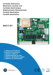
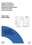
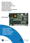
Centrale elettronica Electronic control unit Centrale électronique Elektronische Steuereinheit Central electrónica Central electrónica 900CT-24SU 900CT-24SBA IT GB F D E P MANUALE ISTRUZIONI INSTRUCTION MANUAL MANUEL D'EMPLOI BEDIENUNGSANLEITUNG MANUAL DE INSTRUCCIONES MANUAL DE INSTRUÇÕES Keyautomation S.p.A ITALIANO ATTENZIONE: Leggere attentamente le istruzioni prima di eseguire l’installazione. La non osservanza delle suddette istruzioni, l’uso improprio o un errore di collegamento potrebbe pregiudicare la sicurezza o il corretto funzionamento del dispositivo, e quindi dell’intero impianto. Si declina ogni responsabilità per eventuali malfunzionamenti e/o danni dovuti derivanti dalla loro inosservanza. ATTENZIONE: Questo apparecchio non è destinato a essere usato da persone (Bambini compresi) le cui capacità fisiche, sensoriali o mentali siano ridotte, oppure con mancanza di esperienza o di conoscenza, a meno che esse abbiano potuto beneficiare, attraverso l’intermediazione di una persona responsabile della loro sicurezza, di una sorveglianza o di istruzioni riguardanti l’uso dell’apparecchio. -I bambini devono essere sorvegliati per sincerarsi che non giochino con l’apparecchio; -Non permettere ai bambini di giocare con i comandi. ATTENZIONE: Gli impianti elettrici e le automazioni devono essere eseguite da personale esperto e qualificato nel rispetto delle norme di legge. Tutti i collegamenti devono essere eseguiti con alimentazione di rete non presente. COLLEGAMENTI ELETTRICI Per garantire l’incolumità dell’operatore e per prevenire danni ai componenti, mentre si effettuano i collegamenti, o si innesta la scheda radio, la centralina non deve essere assolutamente alimentata elettricamente. Per i cavi di alimentazione, linee motori, linea lampeggianti/luce di cortesia, elettroserratura utilizzare un cavo con sezione adeguata alla lunghezza del tragitto.(min 1,5 mmq). Per le alimentazioni ausiliarie i comandi e i contatti di sicurezza una sezione minima di 0,5 mmq. Quando i cavi di comando sono molto lunghi (oltre 30 m) è consigliabile il disaccoppiamento mediante dei relè presso la centralina stessa. Nel caso di intervento di un fusibile, dopo aver rimosso la causa sostituirlo con un altro avente le stesse caratteristiche. Installare i vari dispositivi di sicurezza, finecorsa, fotocellule, costa sensibile, pulsante di stop. Se uno o più dispositivi di sicurezza non vengono installati devono essere cortocircuitati i relativi morsetti con il comune comandi. Tutti i contatti N.C. Abbinati ad uno stesso ingresso devono essere collegati in serie. Tutti i contatti N.A. Abbinati ad uno stesso ingresso devono essere collegati in parallelo. Prevedere elementi di disconnessione dalla rete di alimentazione su posto accessibile. Per l’alimentazione della centralina è previsto l’inserimento di un SEZIONATORE esterno (non in dotazione) indipendente e correttamente dimensionato. Prima di procedere all’attivazione del motore si chiede : • Sbloccare il motore meccanicamente e verificare l’esatto collegamento dei finecorsa in base all’apertura ed alla chiusura dell’anta, il led corrispondente al finecorsa interessato deve SPEGNERSI con il finecorsa attivato • Chiudere manualmente l’anta, effettuare ora un impulso di P/P premendo il pulsante relativo; la prima manovra che deve effettuare l’anta è una APERTURA, se così non fosse togliere alimentazione all’impianto e girare il connettore in modo da invertire l’apre con il chiude. ATTENZIONE I dati e le informazioni indicate in questo manuale sono da ritenersi suscettibili di modifica in qualsiasi momento e senza obbligo di preavviso da parte di Keyautomation S.p.A. 2 900CT-24SU 900CT-24SBA Centrale di comando 1 motore scorrevole o basculante 24Vdc con encoder, finecorsa, frizione elettronica, predisposizione per ricevitore radio e modulo caricabatterie Centrale di comando 1 motore barriera 4/6 mt 24Vdc con encoder, frizione elettronica, predisposizione per ricevitore radio e modulo caricabatterie Ogni altro uso è improprio e vietato. DATI TECNICI ALIMENTAZIONE USCITA ALIMENTAZIONE ACCESSORI TEMPO LAVORO TEMPO PAUSA TEMPERATURA DI FUNZIONAMENTO 900CT-24SU / 900CT-24SBA 24Vac/50Hz 24Vdc 315mA 0-120sec 0-120sec -20°C/+70°C COLLEGAMENTI 9 14 11 10 1 12 13 8 7 2 6 5 15 1 2 3 4 5 6 7 8 9 10 11 12 13 14 15 3 15 4 DESCRIZIONE CN1 Morsettiera collegamenti alimentazione 24Vac CN2 Morsettiera alimentazione motore ed encoder CN3 Morsettiera collegamento finecorsa e lampeggiante CN4 Morsettiera collegamento uscite ( Comandi e Sicurezze ) CN5 Connettore collegamento antenna JP1 Pin RESET (cortocircuitare per un istante per cancellare la corsa memorizzata) JP2 Connettore per Scheda radio ricevente ad innesto JP3 Connettore caricabatterie 900CABAT-30 S1 Pulsante PROG per la programmazione S2 Pulsante passo passo P/P S3 Dip-switch settaggio funzioni ( vedi tabella ) Trimmer POWER per regolazione forza motore F1 Fusibile protezione linea 230Vac 8A ritardato F2 Fusibile protezione accessori 230Vac 315mA ritardato Led di segnalazione ingressi di sicurezza Led acceso = ingresso chiuso 3 ITALIANO MODELLI E CARATTERISTICHE ITALIANO COLLEGAMENTI ELETTRICI Per garantire l’incolumità dell’operatore e per prevenire danni ai componenti, mentre si effettuano i collegamenti, o si innesta la scheda radio, la centralina non deve essere assolutamente alimentata elettricamente. Per i cavi di alimentazione, linee motori, linea lampeggianti/luce di cortesia,elettroserratura utilizzare un cavo con sezione adeguata alla lunghezza del tragitto.(min 1,5 mmq). Per le alimentazioni ausiliarie i comandi e i contatti di sicurezza una sezione minima di 0.5 mmq. Quando i cavi di comando sono molto lunghi (oltre 30 m) è consigliabile il disaccoppiamento mediante dei relè presso la centralina stessa. Nel caso di intervento di un fusibile, dopo aver rimosso la causa sostituirlo con un altro avente le stesse caratteristiche. Installare i vari dispositivi di sicurezza, finecorsa, fotocellule, costa sensibile, pulsante di stop. Se uno o più dispositivi di sicurezza non vengono installati devono essere cortocircuitati relativi morsetti con il comune comandi. Tutti i contatti N.C. Abbinati ad uno stesso ingresso devono essere collegati in serie. Tutti i contatti N.A. abbinati ad uno stesso ingresso devono essere collegati in parallelo. Prevedere elementi di disconnessione nella rete di alimentazione su posto accessibile. Per l’alimentazione della centralina è previsto l’inserimento di un SEZIONATORE esterno (non in dotazione) indipendente e correttamente dimensionato. Tenere separati i cavi di alimentazione da quelli di encoder con una distanza motore-centrale di massimo 10 metri. Non usare cavi multi polo. 24Vmin. 2x1,5 mmq Encoder min. 3x0,5 mmq CONNETTORE CN1 Morsettiera collegamenti alimentazione 24Vac, da trasformatore. N 24 Vac F 24 Vac CONNETTORE CN2 Morsettiera collegamento motore 1) +ENC Positivo encoder (rosso) 2) SIG Segnale dell’encoder (verde) 3) –ENC Negativo encoder (bianco) 4) CHM1 Alimentazione Motore 5) APM1 Alimentazione Motore CONNETTORE CN3 Morsettiera collegamento finecorsa 6) COMF comune dei finecorsa 7) FA Finecorsa di apertura contatto N.C. il led si spegne quando viene interessato il finecorsa 8) FC Finecorsa di chiusura contatto N.C. il led si spegne quando viene interessato il finecorsa 9) LAMP Collegamento Lampeggiante 10) COM Collegamento Lampeggiante Sia in apertura che in chiusura, si esegue un prelampeggio di 1,5 Sec. Per segnalare all’utente che l’automazione attua una movimentazione. 4 Il lampeggiante deve avere potenza massima 25W 24Vcc, si attiva appena riceve il comando di apertura, si spegne dopo 90 sec. dall’ultima manovra effettuata Nell’ applicazione con motoriduttori 900BR-24 / 900BR-24K / 900BR-624 / 900BR-624K l’uscita Luce di Cortesia viene utilizzata come seconda connessione del Lampeggiante - NC Finecorsa APRE COMUNE 24Vac/dc + 1 2 3 F1 COMUNE TX RX 24Vac/dc - + RG58 NC 1 2 3 4 NC STOP 5 Lampeggiante NA PAR Antenna NA P/P Luce cortesia Alim. accessori NC Finecorsa CHIUDE 24Vac ITALIANO CONNETTORE CN4 Morsettiera collegamento finecorsa 11) P/P Passo/Passo 12) PAR Apre parziale consente di effettuare un’apertura parziale del 40% della corsa appresa 13) FOT Connessione contatto NC Fotocellula 14) STP Comando STOP contatto NC 15) COM Comune collegamento luce di cortesia 16) + Positivo alimentazione accessori 17) TEST Controllo fototest 18) L.C. Collegamento Luce di Cortesia o secondo lampeggiante ITALIANO FUNZIONI DIP-SWITCH Dip N° Funzione ON OFF Un Impulso Apre Un impulso Stop Un impulso Chiude ( sia se si utilizza l’ingresso P/P che dal Telecomando ) Dip 1 Passo/Passo P/P Primo Impulso Apre ed accetta solo la riapertura durante la chiusura Dip 2 Pausa Fotocellula Pausa fotocellula in apertura Fotocellula attiva solo in chiusura con inversione del moto Dip 3 Chiusura Automatica inserita, Chiusura Automatica si abilita il Funzionamento Automatico Chiusura Automatica non abilitata, si abilita il Funzionamento Semiautomatico Dip 4 Encoder o encoder + finecorsa Funzionamento solo con encoder Funzionamento con encoder e finecorsa Dip 5 Percentuale di rallentamento Rallentamento al 30% della corsa Rallentamento al 10 % della corsa Dip 6 Fototest Fototest ABILITATO Fototest NON abilitato N.B.: ogni variazione di funzione viene convalidata a chiusura ultimata N.B.: Nell’utilizzo barriera 900CT-24SBA il DIP N°5 seleziona funzionamento aste 4 o 6 mt e il DIP N°6 non viene utilizzato • DIP N° 5 OFF funzionamento 4mt • DIP N° 5 ON funzionamento 6mt • DIP N° 4 OFF funzionamento con fermo battuta meccanico consigliato per evitare l’oscillazione dell’asta a fine manovra I test di spinta massima sono stati effettuati con le seguenti condizioni : A. Peso Anta 500Kg. Lunghezza anta 5mt. in perfette condizioni meccaniche (o asta 4mt in perfetto bilanciamento) B. Settaggio Dip switch : Trimmer POWER completamente girato in senso ANTIORARIO – Minima forza / Massima sensibilità all’ostacolo Dip 5 = OFF Dip 4 = OFF Il settaggio degli altri dip non influenza l’esito dei test 6 2). Portare l’automazione aperta a piacimento, premere il Pulsante P/P ( Passo/Passo); l’automazione andrà in chiusura sino alla battuta o al finecorsa di chiusura nel caso esso sia inserito, dopo 2 sec. effettuerà l’apertura sino a raggiungere la battuta di apertura completa o il finecorsa di apertura nel caso esso sia inserito ( tutta la procedura di aquisizione delle battute viene eseguita in rallentamento ). La prima manovra che esegue la centrale è una chiusura, questo per permettere all'installatore di poter capire se i due fili di collegamento del motore sono cablati in maniera corretta, nel caso non vi fosse una chiusura eseguire un RESET toccando con la punta di un cacciavite i due Pins siglati con la dicitura RESET, la centralina bloccherà immediatamente il funzionamento permettendo così di invertire la polarità dei cavi che sono stati riscontrati rovesci. 3). dal momento in cui l’automazione è arrivata in apertura completa, inizia il conteggio del tempo di chiusura automatica, trascorso il tempo desiderato, andremo a ripremere il pulsante P/P , il cancello inizierà la manovra di chiusura, dopo aver completamente chiuso la programmazione sarà così terminata uscendo automaticamente dalla procedura di autoapprendimento CONNETTORE RADIO e CARICABATTERIA Le centrali CT-24SU e CT-24SBA è compatibile con i seguenti ricevitori Keyautomation della serie MEMO ad innesto: 900RXI-42 / 900RXI-42R / 900RXI-22 Un impianto con CT-24SU/SBA può funzionare anche in assenza di tensione di rete, bisogna installare due batterie 12V. 2,2Ah. MAX (non fornite) ed un caricabatterie 900CABAT-30 il tutto senza effettuare nessuna modifica all’impianto. In impianti nuovi a fine installazione e collaudo inserire il modulo caricabatterie ad innesto nel rispettivo connettore facendo molta attenzione nell’inserire la giusta polarità dei due cavi di collegamento delle batterie. Sequenza di collegamento: • Togliere alimentazione 230V • Innestare il modulo CABAT-30 • Collegare le due batterie in serie facendo attenzione alla polarità • Verificare che i led delle sicurezze si accendano • Ripristinare la tensione di rete • Le batterie nuove raggiungeranno la carica dopo circa 10 ore. Il numero di manovre eseguibili con alimentazione a batteria dipende da molti fattori: Key automation garantisce 1 ciclo completo in manovra di emergenza nelle seguenti condizioni: • anta 4 mt 600kg o portone basculante max 9 mq o asta 6 mt. • impianto con 1 coppia di fotocellule, ricevente ad innesto e 1 lampeggiante (20W max.) • batterie cariche • entro 5h dalla mancanza linea 230V 7 ITALIANO PROGRAMMAZIONE 1). Premere e mantenere premuto il pulsante PROG. finchè il lampeggiante si accenderà fisso per avvertire l'utente che si è entrati nella procedura di programmazione. ITALIANO AVVERTENZE FINALI • L’installazione dell’automazione deve essere eseguita a regola d’arte da personale qualificato avente i requisiti di legge e fatta in conformità delle direttive vigenti. • Verificare la solidità delle strutture esistenti (colonne, cerniere, ante) in relazione alle forze sviluppate dal motore. • Verificare che vi siano dei fermi meccanici di adeguata robustezza a fine apertura e fine chiusura delle ante. • Fare un’analisi dei rischi dell’automazione e di conseguenza adottare le sicurezze e le segnalazioni necessarie. • Installare i comandi (ad esempio il selettore a chiave) in modo che l’utilizzatore non si trovi in una zona pericolosa. • Terminata l’installazione provare più volte i dispositivi di sicurezza, segnalazione e di sblocco dell’automazione. • Applicare sull’automazione l’etichetta o la targhetta CE contenenti le informazioni di pericolo e i dati di identificazione. • Consegnare all’utilizzatore finale le istruzioni d’uso, le avvertenze per la sicurezza e la dichiarazione CE di conformità. • Accertarsi che l’utilizzatore abbia compreso il corretto funzionamento automatico, manuale e di emergenza dell’automazione. • Informare l’utilizzatore per iscritto (ad esempio nelle istruzioni d’uso) dell’ eventuale presenza di rischi residui non protetti e dell’uso improprio prevedibile. • Predisporre un piano di manutenzione dell’impianto (almeno ogni 6 mesi per le sicurezze) riportando su di un apposito registro gli interventi eseguiti. • Conservare il presente manuale d’istruzioni per future consultazioni. • La ditta Keyautomation S.p.A. si riserva la facoltà insindacabile di apportare, in qualsiasi momento, le modifiche che si rendessero necessarie ai fini di un miglioramento estetico e/o funzionale. SMALTIMENTO Questo prodotto è formato da vari componenti che potrebbero a loro volta contenere sostanze inquinanti. Informarsi sul sistema di riciclaggio o smaltimento del prodotto attenendosi alle norme di legge vigenti a livello locale. Non disperdere nell’ambiente! 8 NOTE ANMERKUNGEN NOTES NOTA NOTES OBSERVAÇÕES WARNING: It is advisable to read the instructions carefully before you start installation. Failure to comply with these instructions, improper use or incorrect connection may compromise the safety or correct operation of the device and hence of the entire system. No liability shall be accepted for any malfunctions and/or damage due to failure to comply with the instructions. The company reserves the right to make improvements to the products. ENGLISH WARNING: This appliance is not intended to be used by persons (including children) whose physical, sensory or mental are reduced, or lack of experience or knowledge, unless they have been able to benefit, through the intermediary of a person responsible for their security, surveillance or statements regarding your use of the appliance. -Children must be supervised to ensure that do not play with the appliance; -Do not allow children to play with the controls. THIS BOOKLET IS TO BE USED ONLY BY THE INSTALLER Installation must be carried out only by professionally qualified personnel in compliance with current legal requirements. All connection must be performed without mains supply. ELECTRICAL CONNECTIONS To ensure operator safety and to prevent damage to the components while connections are being made, or when the radio card is being inserted, the control unit absolutely must not be powered on. For power cords, motor lines, flasher/courtesy light line, and electric lock, use a cable with a crosssection that is suitable for the length (minimum 1.5 mm2). For auxiliary power supplies, controls and safety contacts a minimum section of 0,5 mm2. When the control cables are very long (more than 30 m), de-coupling is suggested using relays at the control unit. If a fuse trips, after removing the cause, replace it with another one of the same type. Install the various safety devices, limit switches, photocells, sensitive rib, stop button. If one or more of the safety devices are not installed, the corresponding terminals must be short circuited with the controls common. All contacts N.C. Assigned to the same input must be connected in series. All contacts N.O. Assigned to the same input must be connected in parallel. Provide disconnecting devices in the power supply network in accessible places. For the power supply of the control unit, there must be an external disconnecting switch (not included), independent and properly sized. Before to activation of the engine we asks: • Unlock the engine mechanically and verify the exact link of the limit switch according to the opening and closing of the door, the led corresponding to the position switches concerned must GO OFF with limit switches activated • manually close the door, make now a boost of P/P by pressing the corresponding button; the first manoeuvre required to effect the APERTURE is one, if not remove power to the facility and turn the connector to reverse the opens with the closes. WARNING The data and information contained in this manual are subject to change at any time and without prior notice from Keyautomation S.p.A. 10 MODELS AND CHARACTERISTICS 900CT-24SU 900CT-24SBA Control unit 1 motor sliding or overhead with encoder, limit switch, electronic clutch, set up for radio receiver and battery charger module Control unit 1 motor barrier 4/6 m with encoder, electronic clutch, set up for radio receiver and battery charger module TECHNICAL DATA POWER SUPPLY ACCESSORIES POWER SUPPLY OUTPUT WORKING TIME PAUSE TIME OPERATING TEMPERATURE 900CT-24SU / 900CT-24SBA 24Vac/50Hz 24Vdc 315mA 0-120sec 0-120sec -20°C/+70°C COLLEGAMENTI 9 14 11 10 1 12 13 8 7 2 6 5 15 1 2 3 4 5 6 7 8 9 10 11 12 13 14 15 3 DESCRIPTION CN1 Supply connection 22Vac CN2 Engine and encoder control CN3 Flashing light and limit switch control CN4 Command and security connection CN5 Antenna conector JP1 Pin RESET JP2 Connector for radio receiver JP3 Connector battery charger 900CABAT-30 S1 Botton PROG S2 Botton step step P/P S3 Dip-switch setting function ( see table ) Trimmer POWER of engine F1 Fuse protection line 230Vac 8A F2 Fuse protection accessory 230Vac 315mA Signaling leds turned on led = close connection 11 15 4 ENGLISH Ogni altro uso è improprio e vietato. ELECTRICAL CONNECTIONS ENGLISH To ensure operator safety and to prevent damage to the components while connections are being made, or when the radio card is being inserted, the control unit absolutely must not be powered on. For power cords, motor lines, flasher/courtesy light line, and electric lock, use a cable with a crosssection that is suitable for the length (minimum 1.5 m²). For auxiliary power supplies, controls and safety contacts a minimum section of 0.5 mm2. When the control cables are very long (more than 30 m), de-coupling is suggested using relays at the control unit. If a fuse trips, after removing the cause, replace it with another one of the same type. Install the various safety devices, limit switches, photocells, sensitive rib, stop button. If one or more of the safety devices are not installed, the corresponding terminals must be short circuited with the controls common. All contacts N.C. Assigned to the same input they must be connected in series. All contacts N.O. Assigned to the same input they must be connected in parallel. Provide disconnecting devices in the power supply network in accessible places. For the power supply of the control unit, there must be an external DISCONNECTING SWITCH (not included), independent and properly sized. Keep the power supply cables and the encoder cables separate with a distance motor-control unit with a maximum of 10 metres. Do not use multi-pole cables. 24Vmin. 2x1,5 mmq Encoder min. 3x0,5 mmq CN1 N F 24 Vac 24 Vac CN2 1) 2) 3) 4) 5) +ENC Positive encoder (red) SIG Encoder Signal (green) –ENC Negative encoder (white) CHM1 Engine supply APM1 Engine supply CN3 6) 7) 8) 9) 10) COMF common of limit switches FA Opening limit switch contact N.C. the led goes off when the limit switch is activated FC Closing limit switch contact N.C. the led goes off when the limit switch is activated LAMP Flasher Connection COM Flasher Connection In both opening and closing, there is a pre-flash of 1,5 sec. to inform the user that the automation activates a movement. 12 P/P Step/Step PAR Open/Partial This is a command that will cause 40% opening of the learned travel FOT Photocell STP Command STOP contact NC COM Common Courtesy light connection + Positive accessory supply TEST fototest check L.C. Courtesy light connection The flashing light must be maximum 25W 24Vcc, activated as soon as it receives the open command, goes off after 90 sec. from the last action performed In installations with following operators: 900BR-24/900BR-24K/900BR-624/900BR-624K, output CURTESY LIGHT is used as second connection for flashing light. - NC Finecorsa OPEN COMMON 24Vac/dc + 1 2 3 F1 COMMON TX RX 24Vac/dc - + RG58 NC 1 2 3 4 NC STOP 13 Flashing light NO PAR Antenna NO P/P Courtesy light Accessory supply NC Finecorsa CLOSED 24Vac ENGLISH CN4 11) 12) 13) 14) 15) 16) 17) 18) DIP-SWITCH FUNCTIONS Dip N° FunCTION ON OFF One Impulse Opens One Impulse Stop One impulse Closes (whether using input P/P or from the Remote Control) ENGLISH Dip 1 Step/step P/P First Impulse Opens and accepts only re-opening during closing Dip 2 Photocell Pause Photocell pause during opening Photocell active only during closure with reversed direction Dip 3 Automatic closing Automatic closure activated, enables Automatic Operation Automatic Closure not enabled, Semi-automatic Operation enabled Dip 4 Encoder or encoder + limit switch Operation only with encoder Operation with encoder and limit switch Dip 5 Slow motion percentage 30% deceleration of travel 10% deceleration of travel Dip 6 Phototest Photo-test ENABLED Photo-test NON enabled N.B.: each function variation is confirmed upon completion of closure N.B.: in use of barrier 900CT-24SBA DIP No.5 selects operation of 4 or 6 m. and DIP N°6 is not used. • DIP No. 5 OFF operation 4 m • DIP No. 5 ON operation 6 m • DIP No. 4 OFF operation with mechanical stop advised to prevent oscillation of rod at end of manoeuvre The tests of maximum force were carried out in the following conditions: A. Weight of Door 500Kg. Length of door 5 m in perfect mechanical conditions (or rod 4 m when perfectly balanced) B. Dip switch setting : POWER trimmer turned completely counter-clockwise - minimum force / Maximum sensitivity to obstacle The setting of the other dip-switches does not affect the result of the test N.B. - The control unit is equipped with a connector for OPTIONAL connection of the CABAT-30, operation on backup battery starts as soon as there is a power outage. 14 2). Place the automation open as desired, press the button P/P (step/step); the automation will close down to the stop or closure limit switch if connected, after 2 seconds it will open until it reaches the complete opening stop or the opening limit switch if it is connected (the entire process of acquisition of stops is carried out at reduced speed). The first manoeuvre carried out by the control unit is a closure. This allows the installer to check whether the two connection wires of the motor are wired correctly, if there is not a closure, perform a RESET by using the tip of a screwdriver to touch the two Pins labelled RESET, the control unit will immediately stop operation thus allowing inversion of the polarity of the cables if they were found to be reversed. 3). When the automation reaches complete opening, the countdown begins for automatic closure, when the desired time has expired, press button P/P again, after closing is complete programming will be finished and the self-learning procedure will be exited automatically CONNECTION OF RADIO and BATTERY CHARGER The control units CT-24SU and CT-24SBA are compatible with the following Keyautomation receivers of the MEMO snap-in series: 900RXI-22 / 900RXI-42 / 900RXI-42R A system with the CT-24SU/SBA can operate even if there is a mains power outage. Two batteries must be installed, 12V 2,2 Ah. (not included) and a 900CABAT-30 battery charger. All of this can be done without making any modifications to the system. For new systems, after installation and testing, insert the snap-in battery charger module in the corresponding connector. Make sure the polarity of the two connecting cables on the batteries is correct. Connection sequence: • Disconnect the 230Vac power supply • Snap in the CABAT-30 module • Connect the two batteries in series. Make sure the polarity is correct • Check that the safety LED’s come on • Re-connect the mains power supply • New batteries charge up after about ten hours. The number of manoeuvres that can be performed under battery power depends on many factors. Key automation ensures 1 complete emergency manoeuvre in the following conditions: • door 4 m 600 kg or overhead door max. 9 m² or rod 6 m. • system with 1 pair of photocells, snap-in receiver and 1 flasher (20W max.) • batteries charged • within 5 hours of 230Vac power supply failure 15 ENGLISH PROGRAMMING 1). Press and hold the PROG. button until the flasher comes on steady to inform you that you have entered programming mode. FINAL WARNINGS ENGLISH • The installation of the automation must be performed properly by qualified personnel in possession of legal requirements and in compliance with machine directive. • Check the solidity of existing structures (columns, hinges, doors) in relation to the force generated by the motor. • Check that there are suitably sturdy mechanical stops at the end of opening and closing travel of the doors. • Analyse the risks of the automation and adopt necessary safety measures and warnings. • install controls (such as the key selector) so that the user is not in a hazardous position. • Upon completion of installation, check the safety devices several times, as well as those for signalling and automation release. • Provide the automation with the EC label or tag that contains the danger information and identification data. • Give the final user the instructions for use, safety warnings and the EC declaration of conformity. • Make sure the user understands proper automatic, manual and emergency operation of the automation. • Inform the user in writing (for example in the instructions for use) of any unprotected residual risks and foreseeable improper use. • Provide a maintenance schedule for the system (at least every 6 months for the safeties) with an appropriate register of work performed. • Keep this instruction manual for future reference. • Keyautomation S.p.A. reserves the right to make, at any time, any modifications which may be required to improve appearance and/or operation. DISPOSAL This product is composed of various components which may in turn contain pollutants. Do not dispose of it in the environment! Find out about the method for recycling or disposing of the product in compliance with current local laws 16 NOTE ANMERKUNGEN NOTES NOTA NOTES OBSERVAÇÕES GUARANTEE CERTIFICATE CERTIFICATO DI GARANZIA (in riferimento all’articolo 1519 bis ss. cc..) KEYAUTOMATION congratulates with you for the excellent choise. We would like to remind our customers that in order to obtain the maximum operation of the system it is neccessary to use only accessories, spare parts and components sold by KEYAUTOMATION. This certificate should be read carefully, filled in all its parts and preserved to avoid the guarantee to become invalid. The guarantee takes effect from the date of purchase/installation of the system and it lasts for 24 months. We remind users that products will be covered by guarantee only if the coupon concerning the producing company is sent back through certified mail to: Keyautomation si congratula con Lei per la scelta effettuata, al fine di avere una durata massima dell’impianto Le ricordiamo di utilizzare solamente accessori, ricambi e componenti Keyautomation. Il presente certificato dovrà essere letto accuratamente, compilato in tutte le sue parti e conservato pena l’annullamento della garanzia. La garanzia decorre dalla data di acquisto/installazione dell’impianto ed ha validità 24 mesi. Ricordiamo all’utente che per attivare la garanzia è necessario rispedire il tagliando relativo all’azienda costruttrice a mezzo raccomandata presso: KEYAUTOMATION S.p.A. Via A.Volta, 30 30020 Noventa di Piave (VE) Keyautomation S.p.A. Via A.Volta, 30 30020 Noventa di Piave (VE) KEYAUTOMATION ensures that its products are flawless and that they underwent quality and functionality tests. KEYAUTOMATION technical service will decide whether the guarantee is to be applied and its judgement will be incontrovertible. The guarantee is no longer valid in the following cases: • products sent back after more than 24 months from purchase/installation; • installation/use not in compliance with given instructions; • disregard, inappropriate repair or damage caused during transport; • repairs carried out by not authorized personnel or inadequate; • it is clear that the product was damaged and disassembled without techni- cal assistance; • natural phenomena, fraud or external causes for which KEYAUTOMATION is not responsible; • the guarantee coupon and/or the receipit/invoice has not been preserved; • the enclosed coupon has not been filled in and sent it back. KEYAUTOMATION declines every responsability for possible direct or indirect damage to things, people or animals caused by the non-compliance of all or some of the prescriptions and intructions enclosed to the product and by the lack of compliance with directives of installations in force. We would also remind customers to preserve the receipt or invoice in order to be able to submit it, if technical interventions are needed. In our web site www.keyautomation.it, customers can find useful addresses and telephone numbers, in case they need to contact their nears centre of assistance. TAGLIANDO DI GARANZIA - GUARANTEE COUPON DATI APPARECCHIO - TECHNICAL DATA OF DEVICE: MODELLO - MODEL: N° MATRICOLA - NUMBER: DATAACQUISTO - PURCHASING DATE: DATA INSTALLAZIONE - INSTALLATION DATE: DATI DELL’UTILIZZATORE / USER’S DETAILS: COGNOME/NOME - SURNAME/NAME : VIA - STREET . N° CAP - POST CODE CITTÀ - CITY/TOWN PROV TEL LUOGO INSTALLAZIONE - INSTALLATION SITE DATI DELL’INSTALLATORE - DETAIL OF THE INSTALLING COMPANY : COGNOME / RAG.SOCIALE - SURNAME / NAME OF THE COMPANY VIA - STREET N° CAP - POST CODE CITTÀ - CITY/TOWN PROV TEL FAX P.IVA - VAT NUMBER Firma installatore per accettazione delle clausole, condizioni generali di garanzia e trattamento dati personali, (legge 675 del 31/12/1996), l’installatore dichiara inoltre di aver compilato la garanzia impianto per quanto di propria competenza e responsabilità. FIRMA IN ORIGINALE TIMBRO INSTALLATORE - STAMP OF THE INSTALLING COMPANY: ORIGINAL SIGNATURE TIMBRO RIVENDITORE - RETAILER’S STAMP KEYAUTOMATION garantisce che i suoi prodotti sono esenti da difetti di produzione e sono stati sottoposti a test di qualità e funzionalità. Il giudizio sull’applicabilità della garanzia è delegato al servizio tecnico di KEYAUTOMATION ed è insindacabile. La garanzia perde di validità qualora: • siano passati i termini previsti di 24 mesi dalla data di acquisto/ installazione; • installazione e/o uso non conforme alle istruzioni; • manomissioni, negligenza o danni da trasporto; • manutenzione non conforme o effettuata da personale non autorizzato; • sia evidente che il prodotto è stato alterato o smontato senza assistenza tecnica; • fenomeni naturali, dolo o traumi esterni non imputabili a KEYAUTOMATION; • mancata presentazione di tagliando di garanzia e/o scontrino/ fattura fiscale; • mancata compilazione e spedizione del tagliando allegato. KEYAUTOMATION declina ogni responsabilità per eventuali danni diretti od indiretti a cose, persone o animali derivanti dalla inosservanza di tutte o parti delle prescrizioni ed istruzioni allegate al prodotto e alla mancata osservanza delle direttive di installazioni vigenti. Ricordiamo inoltre al cliente di conservare lo scontrino o la ricevuta fiscale per poterlo esibire ogni qualvolta si renda necessario un intervento tecnico. Qualora il cliente desiderasse contattare il centro assistenza più vicino potrà visitare il nostro sito www.keyautomation.it, dove troverà indirizzi e numeri di telefono utili. DICHIARAZIONE “CE” DI CONFORMITA’ Il costruttore: The manufacturer: Keyautomation S.p.A Indirizzo: Address: Via Alessandro Volta, 30 Noventa di Piave (Ve) DICHIARA CHE IL SEGUENTE APPARATO DECLARES THAT THE FOLLOWING EQUIPMENT Descrizione: Per un motore scorrevole/basculante 24 Vdc con encoder, innesto radio. Per un motore barriera 24 Vdc con encoder, innesto radio. Description: For 1 sliding gate 24 Vdc motor with encoder, plug-in radio card option. For 1 barrier motor, 24 Vdc with encoder, plug-in radio card option. Modello: Model: go24 Codice: Code: 900CT-24SU - 900CT-24SBA • Risulta conforme con quanto previsto dalle seguenti Direttive Comunitarie, comprese le ultime modifiche e con la legislazione nazionale di recepimento • Is in conformity with the provisions of the following Community Directives, including the latest modifications and with the assimilating national legislation EN 61000-6-2 : 2005 Compatibilità elettromagnetica (EMC) Norma generica – Immunità per gli ambienti industriali IEC 61000-6-2 : Electromagnetic compatibility (EMC) – Generic standards – Immunity for industrial environments EN 61000-6-3 : 2007 Compatibilità elettromagnetica (EMC) Norma generica – Emissione per gli ambienti residenziali, commerciali e industria leggera IEC 61000-6-3 : Electromagnetic compatibility (EMC) Generic Standards - Emission Standard for Residential, Commercial and Light-Industrial Environments EN 61000-3-2 : 2006 Compatibilità elettromagnetica (EMC) Limiti per le emissioni di corrente Armonica ( apparecchiature con corrente di ingresso ≤16 A per fase IEC 61000-3-2 : Electromagnetic compatibility (EMC) - Part 3-2: Limits - Limits for harmonic current emissions (equipment input current ≤16 A per phase) EN 61000-3-3 : 1995+A1:2001+A2:2005 Compatibilità elettromagnetica (EMC) Limitazione delle fluttuazioni di tensione e flicker in sistemi di alimentazione in bassa tensione per apparecchiature con corrente nominale ≤16 A e non soggette ad allacciamento su condizione IEC 61000-3-3 Electromagnetic compatibility (EMC) - Part 3-3: Limits - Limitation of voltage changes, voltage fluctuations and flicker in public low-voltage supply systems, for equipment with rated current ≤16 A per phase and not subject to conditional connection La Keyautomation S.p.A garantisce detta conformità esclusivamente nel caso in cui l’apparecchiatura venga utilizzata come unità di comando/gestione di motorizzazioni nelle configurazioni tipiche di installazione e con periferiche conformi alle Direttive Europee. Keyautomation S.p.A. guarantees such a conformity only if the control unit is used as a control/management unit for automation system in typical configuration of installation and with peripherals which conform to the European Directives Noventa di Piave 07/01/2009 Il Rappresentante legale The legal Representative Romeo Bissoli Keyautomation S.p.A Via Alessandro Volta, 30 30020 Noventa di Piave (Ve) Italia T. +39 0421.307.456 F. +39 0421.656.98 [email protected] Дэнис ® c.f. - p.iva e v.r.t. IT03627650264 r.e.a. VE326953 cap. soc. € 1.000.000,00 i.v. reg. imp. VE03627650264 www. keyautomation. it 580ISCT-24SUSBA rev02 light