1
V5680-581-00.book Seite 19 Dienstag, 2. Mai 2006 2:06 14
¼
Risk of fatal injury from electrical current.
The dimmer is not suitable for safety isolation.
The outputs may carry an electrical current even
when the dimmer is switched off. Always
disconnect the fuse in the incoming circuit from
the supply before working on connected loads.
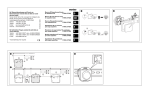
1 Wire the dimmer (Figure §A) as required for
individual applications:
V5680-581-00.book Seite 20 Dienstag, 2. Mai 2006 2:06 14
– Figure &: Dimmer A with extension units:
Example of connection with a push-button B, an
extension insert C and an extension TELE insert
D.
Note: Always wire the right channel (Figure
(Figure „B) only functions when a load
(luminaire) is connected on the right channel
(Figure „A).
– Figure $: Dimmer A as stand-alone device (only
right channel connected)
– Figure %: Dimmer A as stand-alone device (right
and left channel connected)
19
V5680-581-00.book Seite 22 Dienstag, 2. Mai 2006 2:06 14
How to operate the dimmer
Operate the dimmer via one of the following:
– Rockers on the dimmer itself
– Sensor cover on an electrical extension unit
– Mechanical extension unit (conventional pushbutton)
How to put the dimmer into operation
After installation:
1 Switch on the mains voltage.
Figure §:
2 Install the dimmer A into the flush-mounted box.
2 For each channel, press the corresponding key to
perform load detection.
3 Push the rockers D onto push-button module C.
The corresponding channel will be switched on and off
several times (flickers) for approx. 10 seconds. The
dimmer then briefly switches off and dims to maximum
brightness.
The dimmer has detected the load and is ready for
operation.
½
| „A) first. The left channel of the dimmer
V5680-581-00.book Seite 21 Dienstag, 2. Mai 2006 2:06 14
Attention: The plug prongs on the rear of the
push-button module can become bent if tilted
excessively. Therefore always plug the pushbutton module in as straight as possible.
4 Place push-button module C with its frame B onto
the dimmer A.
| voltage, a load detection must be carried out.
Note: After each interruption of the mains
20
21
V5680-581-00.book Seite 23 Dienstag, 2. Mai 2006 2:06 14
V5680-581-00.book Seite 24 Dienstag, 2. Mai 2006 2:06 14
Switching memory function for each channel on
and off
What should I do if there is a problem?
1 Actuate the respective rocker at least ten times
quickly in a row to switch the memory function on or
off.
The dimmer regularly dims down or switches off
during operation.
Allow the dimmer to cool down and reduce the
connected load.
The dimmer cannot be switched back on.
– Allow the dimmer to cool down further and reduce
the connected load.
– If there is a short circuit, have an electrician rectify
it. The dimmer must now recognise the load again.
If necessary, switch the dimmer on once for load
detection (see "How to put the dimmer into
operation").
Switching/dimming connected luminaires
– Switching on/off: press the button briefly
(Figure !A)
– Dimming brighter/darker: press the button and hold
it down
(Figure !B)
Both channels cannot be operated any more.
– Check light on the right channel (Figure „A).
The left channel cannot be operated any more.
– Check light on the left channel (Figure „B).
22
23
24