1
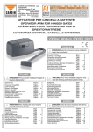
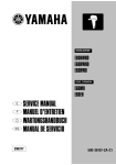
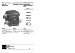
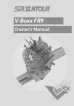
Istruzioni d’uso Montageanleitung Notice de montage Instruction sheet Instrucciones de empleo MA-MH-ML 630-1250 MA-MH 630-1600ES MS 630-1600 PART. Y2961E A A 1 B 1 C 3 D 1 E 1 F 1 G 1 H 1 I 1 L 1 M 1 N 1 O 1 P 2 06/13-01 GF 1 AUTO MAN LOCK MANUAL READY CLOSE OPEN OPERATION B E I C D H F N L P M G O 1 AUTO 8 3 4 2 MAN LOCK 7 5 READY CLOSE 6 1 -Selettore modalità di funzionamento 2 - Selettore chiusura/apertura in modalità manuale 3 -Indicatore dell’operazione da selezionare sul selettore 2 (solo per manovra in modalità manuale) 4 -Leva di manovra per operazioni di apertura e chiusura in MAN 5 -Indicatore dello stato dei contatti principali interruttore 6 -Pulsante di apertura rapida o emergenza Sgancio 7 -Blocco a lucchetti in posizione aperto 8 -Alloggiamento per blocco a chiave in aperto 1 -Schalter für Betriebsmodus 2 - Schalter öffnen/schließen im manuellen Modus 3 -Anzeige des zu wählenden Vorgangs am Schalter 2 (nur zur Steuerung im manuellen Modus) 4 -Steuerhebel zum Öffnen und Schließen in MAN 5 -Anzeige des Zustands der Schalter-Hauptkontakte 6 -Taste zur schnellen Öffnung oder Notfall-Entsicherung 7 -Verriegelung in offener Position 8 -Sitz der Schlüsselverriegelung geöffnet OPEN MANUAL OPERATION 2 1 -Sélecteur modalité de fonctionnement. 2 - Sélecteur fermeture/ouverture en modalité manuelle. 3 -Indicateur de l’opération à sélectionner sur le sélecteur 2 (uniquement pour commande en modalité manuelle). 4 -Levier de commande pour opérations d’ouverture et de fermeture en MAN. 5 -Indicateur de l’état des contacts principaux de l’interrupteur. 6 -Bouton d’ouverture rapide ou urgence déclenchement. 7 -Verrouillage en position ouverte. 8 -Logement pour verrouillage à clé en position ouverte. 1 -Operation mode selector. 2 -Open/Close selector in manual mode. 3 -Indicator of the operation to be selected on selector 2 (only for operations in manual mode). 4 -Operating lever for opening and closing operations in MAN. 5 -Status indicator of the main switch contacts. 6 -Quick opening or Emergency release pushbutton. 7 -Padlocks in open position. 8 -Housing for keylock in open position. 1 -Selector modos de funcionamiento 2 - Selector cierre/apertura en el modo manual 3 -Indicador de la operación a seleccionar en el selector 2 (sólo para maniobras en modo manual). 4 -Palanca de maniobra para operaciones de apertura y cierre en MAN 5 -Indicador del estado de los contactos principales interruptor 6 -Pulsador de apertura rápida o emergencia de desenganche 7 -Bloque con candados en posición abierto 8 -Alojamiento para bloque de llave en posición abierto Funzionamento automatico - Automatischer Betrieb - Fonctionnement automatique Automatic operation - Funcionamiento automático AUTO MAN 3 LOCK Chiusura su comando elettrico mantenuto ≥ 4 sec. Apertura su comando elettrico mantenuto ≥ 8 sec. Riarmo/apertura su comando elettrico mantenuto ≥ 8 sec. In questa modalità non è possibile effettuare operazioni di apertura e chiusura manuali tramite l’apposita leva 4; questa è meccanicamente bloccata. Schließen durch elektrische Steuerung, ≥ 4 sec gedrückt halten Öffnen durch elektrische Steuerung, ≥ 8 sec gedrückt halten Rückstellen/öffnen durch elektrische Steuerung, ≥ 8 sec gedrückt halten In diesem Betriebsmodus kann das Öffnen und Schließen nicht manuell über den Hebel 4 erfolgen; dieser ist mechanisch blockiert. AUTO Fermeture sur commande électrique à action maintenue ≥ 4 sec. Ouverture sur commande électrique à action maintenue ≥ 8 sec. Réarmement/ouverture sur commande électrique à action maintenue ≥ 8 sec. Dans cette modalité, il n’est pas possible d’effectuer des opérations d’ouverture et de fermeture manuelles à l’aide du levier 4; ce dernier est bloqué mécaniquement. MAN LOCK AUTO Closing on electric control held down ≥ 4 sec. Opening on electric control held down ≥ 8 sec. Resetting/Opening on electric control held down ≥ 8 sec. This mode is unable to perform manual opening and closing operations with the lever - 4; it is mechanically disabled. MAN LOCK Cierre en el comando eléctrico mantenido ≥ 4 seg. Apertura en el comando eléctrico mantenido ≥ 8 seg. Rearme/apertura en el comando eléctrico mantenido ≥ 8 seg.. En este modo no es posible efectuar operaciones de apertura y cierre manuales por medio de la palanca 4, ya que se bloquea mecánicamente. Funzionamento manuale - Manueller Betrieb - Fonctionnement manuel Manual operation - Funcionamiento manual AUTO MAN AUTO LOCK MAN 4 LOCK 1 AUTO 3 4 MAN LOCK 5 READY CLOSE OPEN MANUAL OPERATION AUTO 2 • Posizionare il selettore (1) dalla posizione AUT alla posizione MAN. • In MAN non è possibile eseguire manovre elettriche di chiusura e apertura. • Verificare l’indicatore dello stato dei contatti (5) e accertarsi della condizione dell’interruttore. • Verificare l’indicatore (3) e accertarsi che il selettore (2) sia posizionato correttamente. • Azionare la leva di manovra (4) fino al completamento dell’operazione desiderata. • Amener le sélecteur (1) de la position AUT à la position MAN. • En MAN, il n’est pas possible d’effectuer des commandes électriques de fermeture et d’ouverture. • Contrôler l’indicateur de l’état des contacts (5) et s’assurer de la bonne position de l’interrupteur. • Contrôler l’indicateur (3) et s’assurer que le sélecteur (2) est correctement positionné. • Actionner le levier de commande (4) jusqu’au terme de l’opération voulue. • Den Schalter (1) von AUT auf MAN positionieren. • Wenn auf MAN geschaltet, kann das Öffnen und Schließen nicht elektrisch erfolgen. • Die Anzeige des Zustands der Kontakte (5) und des Schalters kontrollieren. • Die Anzeige (3) kontrollieren und sicherstellen dass der Schalter (2) richtig positioniert ist. • Den Steuerhebel (4) betätigen bis der gewünschte Vorgang beendet ist. • Move the selector (1) from the AUT position to the MAN position. • In MAN mode it is not possible to perform electric opening and closing operations. • Check the status indicator of the contacts (5) and verify the condition of the switch. • Check the indicator (3) and make sure that the selector (2) is correctly positioned. • Use the operating lever (4) until the required operation has been completed. 2 MAN LOCK • Lleve el selector (1) de la posición AUT a la posición MAN. • En MAN no es posible efectuar maniobras eléctricas de cierre y apertura. • Verifique el indicador del estado de los contactos (5) y compruebe la condición del interruptor. • Verifique el indicador y (3) y compruebe que el selector (2) esté colocado correctamente. • Accione la palanca de maniobra (4) hasta completar la operación deseada Funzionamento manuale - Manueller Betrieb - Fonctionnement manuel Manual operation - Funcionamiento manual AUTO MAN LOCK Operazione di chiusura interruttore - Schalter schließen Opération de fermeture interrupteur - Switch opening operation - Operación de cierre del interruptor AUTO MAN LOCK READY CLOSE OPEN I 0 5 3 2 5 3 Operazione di apertura interruttore - Schalter öffnen Opération d’ouverture interrupteur - Switch opening operation - Operación de apertura del interruptor READY CLOSE OPEN 0 I 5 3 2 4 5 3 Operazione di reset dopo sgancio interruttore - Schalter nach dem Entsichern desselben zurückstellen Opération de réarmement après ouverture interrupteur - Reset operation after trip Operación de restablecimiento después del desenganche del interruptor READY CLOSE OPEN 0 5 0 3 2 4 3 5 3 4 5 Sganciare; togliere coperchio interruttore e coprimaniglia ed eliminare le viti evidenziate. Entsichern; Schalter- und Griffabdeckung abnehmen und die angegebenen Schrauben abschrauben. Déclencher; retirer couvercle interrupteur et cache poignée puis retirer les vis indiquées. Release; remove switch cover and handle cover and remove the screws shown. Desenganche; retire la tapa del interruptor y la cubierta de la manija y saque los tornillos que se destacan. 6 Togliere la mostrina. Abdeckplatte entfernen. Retirer le cache. Remove the front cover. Saque la mirilla. 7 Applicare la targhetta. Schild anbringen. Appliquer la plaquette. Put on the nameplate . Aplique la placa. CRAC Forare ed eliminare i due diaframmi. Die beiden Blenden durchbohren und entfernen. Percer et éliminer les deux diaphragmes. Drill and remove the two diaphragms. Perfore y retire los dos diafragmas. Ø5 4 8 Bobina di lancio. Impulsspule. Déclencheur à émission de courant. Shunt release. Bobina de lanzamiento. Bobina di minima tensione. Mindestspannungsspule. Déclencheur à minimum de tension. Undervoltage release. Bobina de tensión mínima. 9 10 F E E Montare il coperchio interruttore ed inserire il blocchetto e la leva. Schalterabdeckung montieren und Verriegelung und Hebel einsetzen. Monter le couvercle interrupteur et mettre en place le bloc et le levier. Install the switch cover and insert the block and lever. Monte la tapa del interruptor e inserte el bloque y la palanca. F F F D E D D D E N L N L N max 1.8 Nm1.8 Nm max maxL 1.8 Nmmax 1.8 Nm N L 11 AUTO AUTO MAN AUTO MAN LOCK AUTO LOCK 12 MAN MAN LOCK LOCK N.B.: Portare il selettore (1) modalità di funzionamento, sulla posizione MAN. N.B. Den Schalter (1) für den Betriebsmodus auf MAN schalten. N.B.: placer le sélecteur (1) de modalité de fonctionnement sur la position MAN. N.B.: Move the operation mode selector (1) to the MAN position. N.B.: Lleve el selector (1) modos de funcionamiento a la posición MAN. 5 Per posizionare la leva caricare la molla. Um den Hebel zu positionieren, die Feder laden. Pour positionner le levier, faire pression sur le ressort. Load the spring in order to set the lever. Para colocar la palanca, tense el muelle. 13 Montare la base motore sull’interruttore facendo attenzione all’inserimento della maniglia tra i due rulli. Die Motorgrundplatte montieren und darauf achten dass der Griff zwischen den beiden Rollen positioniert wird. Monter la base moteur sur l’interrupteur en veillant à introduire la poignée entre les deux rouleaux. Install the motor base on the switch; insert the handle between the two rolls carefully. Monte la base del motor en el interruptor, prestando atención a colocar la manija entre los dos rodillos. C H M G C C 14 Tirare la leva (4) per poter posizionare la calotta. Hebel (4) ziehen um die Abdeckung positionieren zu können Tirer le levier (4) pour pouvoir positionner la calotte. Pull the lever (4) so as to position the protection shield. Tire la palanca (4) para colocar la tapa. AUTO MAN LOCK Avvitare la calotta motore. Motorabdeckung festschrauben. Visser la calotte moteur. Tighten the motor protection shield. Enrosque la tapa del motor. I 1 Nm max 6 AUTO MAN AUTO Installazione lucchetti - Installation der Verriegelungen LOCK Installation verrouillage cadenas - Padlock installation - Instalación de los candados AUTO A Sganciare e mantenere premuto. Entsichern und gedrückt halten. Déclencher et maintenir enfoncé. Release and keep pressed . Desenganche y mantenga presionado. MAN 15 LOCK MAN Posizionare il selettore su blocco lucchetti. Schalter auf Verriegelung positionieren. LOCK Positionner le sélecteur sur verrouillage. Position the selector on padlocks. Lleve el selector al bloque de candados. AUTO MAN LOCK n°3 - min Ø 5mm - max Ø 6mm n°3 - min Ø 5mm - max Ø 6mm n°3 - min Ø 5mm - max Ø 6mm 16 Installazione blocco chiave - Installation der Schlüsselverriegelung Installation verrouillage clé - Keylock installation - Instalación del bloque de llave Togliere calotta motore. Motorabdeckung abnehmen. Retirer la calotte moteur. Remove motor protection shield. Desmonte la tapa del motor. AN AUTO AUTO MAN n°3 - min Ø 5mm - max Ø 6mm MAN LOCK LOCK LOCK MAN Montare blocco a chiave. Schlüsselverriegelung montieren. Monter le bloc de verrouillage clé. Install keylock. Monte el bloque de llave . LOCK M7375B M7375B M7375B Y A < 23 17 P 27,5 ø 3,5 O M7375B 13 AUTO 3 73 82 CRAC Y MAS 7 17 1 3 4 6 F MAN A C B D Q1 E M M:Motore - Motor - Moteur Motor - Motor 2 5 1- 2- 3- 4-5- 6-7- Chiusura Comune Apertura Manuale Interruttore aperto 1- 2- 3- 4-5- 6-7- Fermeture Commun Ouverture Manuel C ouvert Interrupteur 1– 2- 3- 4-5- 6-7- Schließen Gemein Öffnen Manuell Schalter geöffnet 1- 2- 3- 4-5- 6-7- Closed Common Open Manual Switch open 1 A 3 MAN 4 F 7 1 - Cierre 2 - Común 3 - Apertura 4-5- Manual 6-7- Interruptor abierto 6 C B D E Q1 M 2 5 7 AC: contatti NC;con motore in posizione di Manuale (MAN) o di Lucchettato (LOCK) tagliano l’alimentazione al circuito di chiusura ed apertura del motore; questi si aprono anche in caso di asportazione del coperchio motore. BD: contatto 1NC+1NO fine corsa di apertura e fine corsa di chiusura.(motore rappresentato in posizione di aperto) F contatto di segnalazione motore in Manuale E contatto di segnalazione interruttore Chiuso AC: contacts NC; avec le moteur en position Manuel (MAN) ou de verrouillage (LOCK), coupent l’alimentation du circuit de fermeture et d’ouverture du moteur ; ils s’ouvrent également en cas de retrait du couvercle moteur. BD: contact 1NC+1NO fin de course d’ouverture et fin de course de fermeture (moteur représenté en position d’ouverture) F contact de signal moteur en Manuel E contact de signal interrupteur Fermé AC: NC Kontakte; wenn der Motor auf Manuell (MAN) oder auf Verriegelung (LOCK) geschaltet ist, unterbrechen sie die Stromversorgung des Kreislaufs Schließen/Öffnen des Motors. Diese öffnen sich auch wenn die Motorabdeckung abgenommen wird. BD: Kontakt 1NC+1NO Endschalter für Öffnen und Endschalter für Schließen (der Motor ist in offener Position abgebildet) F Signalkontakt Motor auf Manuell E Signalkontakt Schalter geschlossen AC: NC contacts; when the motor is in Manual position (MAN) or Locked position (LOCK), they cut the power at the opening and closing circuit of the motor; these also open when removing the motor cover. BD: 1NC+1NO opening and closing end-stop contact. (motor represented in open position) F contact for motor signalling in Manual mode E contact for Closed switch signalling 8 AC: Contactos NC; con motor en la posición manual (MAN), o con candado (LOCKED) cortan la alimentación al circuito de cierre y apertura del motor; estos contactos se abren incluso al desmontar la tapa del motor. BD: contacto 1NC+1NO tope de apertura y tope de cierre (el motor se representa en la posición de abierto) F contacto de señalización motor en la posición manual E contacto de señalización interruptor cerrado 1. Pulsante azionato senza dispositivo a scatto shunt. 1. Tastensteuerung ohne Entsicherung der Impulsspule. 1. Bouton actionné sans dispositif à déclenchement de shunt. 1. Push button operated without st release. 1. Pulsador accionado sin disparo de bobina en derivación. SC: trip contact of DPX SC: trip contact of DPX SC: trip contact of DPX ON OFF ON ON KA KA KA1 KA KB KB1 KA1 KA1 KB1 KB KB1 KB ON 51 OFF OFF SC 51 51 SC of DPX SC: trip contact SC 54 54 54 OFF KB2 KA KB2 KB2 KA1 3 1 1 1 4 3 3 KB KB1 6 4 4 C A MAN 1 A MAN C3 D B B D B Q1 Q1 Q1 Q1 M A MAN M M B 2 2. Pulsante azionato con apertura rapida tramite dispositivo a scatto shunt. 2. Tastensteuerung mit schneller Öffnung durch Entsicherung der Impulsspule. C 4 D E F 51 ONLY for SCONLY for automatic ONLYautomatic for KA2 reset after 54 KA2 automatic reset after tripreset after trip trip ONLY for KA2 automatic reset after trip E E D 7 5 5 2 6 C 5 2 M 2 F F A MAN KB2 6 6 F KA2 7 7 5 E 7 2. Bouton actionné avec ouverture rapide via dispositif à déclenchement de shunt. 2. Push button operated with fast opening by st release. 2. Botón accionado con apertura rápida y disparo de bobina en derivación. SC: trip contact of DPX SC: trip contact of DPX SC: trip contact of DPX OFF ON KA KA KA ST KA KB2 K 1 4 3 C1 C1 C1 Q1 Q1 Q1 Q1 2 C2 C1 C2 C2 C2 3. Switch operated. 3. Accionado por el interruptor. C 2 2 5 2 M D 4 6 E F E E C K = NC 16A 250V K = NC 16A 250V K =16A NC 250V 16A 250V KA1 = NO KA1 = NO 16A 250V NO 250V 16A 250V KB1 =KA1 NO=16A KB1 = NO 16A 250V KB1 = NO 16A 250V K = NC 16A 250V KA1 = NO 16A 250V KB1 = NO 16A 250V D 7 5 5 7 7 E 4. Schaltersteuerung mit schneller Öffnung durch Entsicherung der Impulsspule. 4. Interrupteur actionné avec ouverture rapide via dispositif à déclenchement de shunt. 4. Switch operated with fast opening by shunt trip release. 4. Interruptor accionado con apertura rápida y disparo de bobina en derivación. ST ST K = NC 16A 250V Chiudi Apri K = NC 16A 250V Chiudi Apri CloseChiudi Open ApriKA1 = NO K =16A NC 250V 16A 250V Close Open KA1 = NO 16A 250V Close Open NO 250V 16A 250V KB1 =KA1 NO=16A ST K K 1 ST E 2 KB1 = NO 16A 250V 3 4 6 KB1 = NO 16A 250V 1 3 Apri 4 6 Chiudi 1 3 4 6 K = NC 16A 250V Close KA1 = NO 16A 250V F Open F F KB1 = NO 16A 250V A MAN C MAN A C 1 3 4 6 A MAN C K K B 7 5 C 51 ONLY for SCONLY for automatic ONLY for KA2 automatic reset after 54 KA2 automatic reset after tripreset after trip trip ONLY for KA2 automatic reset after trip 24. Interruttore 5 7azionato con apertura rapida tramite dispositivo a scatto shunt. D 5 2 M E M A MAN M M B F F C A MAN 1 C3 A MAN D B D B 6 6 5 7 B Q1 C1 E 7 Q1 C1 2 4 4 KA2 Q1 M C2 M BM 51 51 SC of DPX SC: trip contact SC 54 54 54 5 7 9 B D D A MAN M BM C2 M A MAN KB1 6 C1 Q1 3 A MAN Chiudi Apri Chiudi Apri CloseChiudi Open Apri Close Open Close Open 1 3 4 6 1 3 4 6 1 3 4 6 Chiudi Apri F Close Open F F C A MAN MAN C A 1 3 4 6 C A MAN D B D B D B E F Q1 1 KB F B Q1 KA1 3 1 K 3. Interruttore azionato. 3. Schaltersteuerung. 3. Interrupteur actionné. 51 OFF OFF SC OFF K ST KB2 KB1 KB ST K Q1 KB1 KB C1 KB2 KB1 KA1 KA1 ST ON KB2 KA1 KB C2 ON C2 ON Q1 2 D 2 M 2 E E D 5 2 E F C 7 5 E 5 5 7 7 7 2 1 KS = NC 16 A 250 VAC 5 4 6 7 Blocco di emergenza Emergency stop Motore principale Main motor 3 2 3 4 5 6 RELE' SECONDARIO SEC. RELAY 2 1 5 8 RELE' PROG. 1 PROG. 1 RELAY 7 4 6 7 10 11 13 14 RELE' PROGRAMMABILE 3 PROG. 3 RELAY 12 17 16 15 INGRESSI DIGITALI DIGITAL INPUTS 20 19 18 22 21 Ritiro principale Scatto principale - + ALIM. AUS. DC DC AUX SUPPLY 24 23 ALIM. AUS. AC AC AUX SUPPLY 27 26 25 Ritiro sec. Scatto sec. CENTRALINA DI COMMUTAZIONE AUTOMATICA DI RETE ELECTRONIC CONTROL BOX M7000CB - M7000CB/EVO RELE' PROGRAMMABILE 2 PROG. 2 RELAY 9 Motore secondario Sec. motor 3 Secondario N L2 L3 N L2 SECONDARIA SEC. L1 100-690 Vac 50/60 Hz MISURA DI TENSIONE VOLTAGE INPUTS PRINCIPALE MAIN L1 L3 Art. M7875B xxx Art. M7875B xxx RELE' PRINCIPALE MAIN RELAY Apertura Com Chiusura Apertura Com Chiusura Opening Com Closing Opening Com Closing 1 KS C1 C2 C1 C2 KM = NC 16A 250 VAC KM Sec. principale Sec. principale Sec. Alimentazione elettrica del motore Tension electric motors Ritiro principale Scatto principale 12-Rosso 52-Rosso 2-Rosso 14-Bianco 54-Bianco 3-Bianco 12-Rosso 52-Rosso 2-Rosso 14-Bianco 54-Bianco 3-Bianco 11-Nero 51-Nero 1-Nero 11-Nero 51-Nero 1-Nero Ritiro sec. 10 Scatto sec. FREE ON Input prog.1 P1.03 P1.05 Input prog.2 Impostazione Com inputs digitali Parametro ˜ Programmazione parametri per lo schema in figura: 0V Art. M7875A xxx Art. M7875A xxx ˜ Schema: BT19B MEGATIKER 1600 Wiring diagram: BT19B MEGATIKER 1600 220-240V Centralina di commutazione Schalteinheit Centrale de commutation Eletronic Control Box Centralita de conmutación con feedback with feedback 2 4 6 Motore principale Main motor 5 7 2 3 4 5 5 4 6 6 Motore secondario Sec. motor 3 RELE' PRINCIPALE MAIN RELAY RELE' SECONDARIO SEC. RELAY Apertura Com Chiusura Apertura Com Chiusura Opening Com Closing Opening Com Closing 1 2 1 8 RELE' PROG. 1 PROG. 1 RELAY 7 7 10 11 13 14 RELE' PROGRAMMABILE 3 PROG. 3 RELAY 12 17 16 15 INGRESSI DIGITALI DIGITAL INPUTS 20 19 18 22 21 - + ALIM. AUS. DC DC AUX SUPPLY 24 23 ALIM. AUS. AC AC AUX SUPPLY 27 26 25 CENTRALINA DI COMMUTAZIONE AUTOMATICA DI RETE ELECTRONIC CONTROL BOX M7000CB - M7000CB/EVO RELE' PROGRAMMABILE 2 PROG. 2 RELAY 9 Sec. principale 3 Ritiro principale Scatto principale 1 Sec. Tension electric motors Ritiro sec. Scatto sec. Alimentazione elettrica del motore Input prog.1 11 Input prog.2 N L2 L3 N L2 SECONDARIA SEC. L1 100-690 Vac 50/60 Hz MISURA DI TENSIONE VOLTAGE INPUTS PRINCIPALE MAIN L1 NOF OFF OFF Com inputs digitali P1.03 P1.04 P1.05 ˜ Impostazione 0V Parametro ˜ L3 Programmazione parametri per lo schema in figura: 220-240V Centralina di commutazione Schalteinheit Centrale de commutation Eletronic Control Box Centralita de conmutación Schema: BT17B MEGATIKER 1600 Art. M7875A xxx Art. M7875B xxx senza feedback Wiring diagram: BT17B MEGATIKER 1600 Art. M7875A xxx Art. M7875B xxx without feedback UTILIZZO SU INVERTITORI DI SORGENTE AUTOMATICI Attenzione: in base alla modalità di utilizzo del motore, cioè: • senza dispositivo di sgancio oppure • con dispositivo di sgancio Il tempo di commutazione tra la linea principale e la linea di emergenza (tempo trascorso tra l’apertura dell’interruttore automatico della linea principale e la chiusura dell’interruttore automatico della linea di emergenza) deve essere rispettivamente superiore o pari a: • 6 sec oppure • 0,5 sec GEBRAUCH MIT UMSCHALTAUTOMATIK Achtung: je nach Betriebsmodus des Motors, d.h.: • ohne Entsicherungsvorrichtung oder • mit Entsicherungsvorrichtung Die für das Umschalten von Hauptleitung auf Notfall-Leitung benötigte Zeit (Zeitintervall zwischen dem Öffnen des automatischen Schalters der Hauptleitung und dem Schließen des automatischen Schalters der Notfall-Leitung) muss höher oder gleich den folgenden Werten sein: • 6 sec oder • 0,5 sec Potenza Assorbita Stromaufnahme Puissance Absorbee Input Power Potencia Absorbida UTILISATION SUR INVERSEURS DE SOURCE AUTOMATIQUES Attention: selon la modalité d’utilisation du moteur, à savoir: • Sans déclencheur ou • Avec déclencheur Le temps de commutation entre ligne principale et ligne de secours (temps entre l’ouverture du disjoncteur de la ligne principale et la fermeture de celui de secours) doit être respectivement supérieur ou égal à: • 6 sec ou • 0,5 sec USE FOR AUTOMATIC CHANGEOVER Caution: according to the usage of the motor, namely: • without tripping device or • with tripping device The changeover time between the main line and the emergency line (time between the opening of the circuit breaker of the main line and the closing of the circuit breaker of the emergency line) must be longer or equal to: • 6 sec or • 0.5 sec USO DE INVERSORES DE FUENTE AUTOMÁTICOS Atención: según el modo de uso del motor, es decir: • sin dispositivo de desenganche ó • con dispositivo de desenganche El tiempo de conmutación entre la línea principal y la línea de emergencia (es decir, el tiempo que pasa entre la apertura del interruptor automático de la línea principal y el cierre del interruptor automático de la línea de emergencia) debe ser respectivamente superior o igual a: • 6 seg ó • 0,5 seg (A) Operazione elettrica (min. contatto trattenuto) Elektrischer Betrieb (min. Haltekontakt) Opération électrique (avec contact maintenu min.) Electric operation (whit hold contact min.) Operación eléctrica (con contacto mantenido mín.) (B) Posizione cambio contatti principali (Max valore di ritardo per ciascuna operazione) Wechselposition Hauptkontakte (max. Verzögerungszeit für jeden Betrieb) Changement de position contacts principaux (retard max. pour chaque opération) Main contacts change position (Max Delay time for each operation) Posición de cambio contactos principales (retardo máximo por cada operación) Sec./ Sek./ Sec./ Sec/ Seg. Sec./ Sek./ Sec./ Sec/ Seg. W/Va Tensione Spannung Tension Voltage Tensión Spunto Anlauf Démarrage Start Arranque Regime Normalbetrieb Régime Steady state Régimen Chiuso Schließen Fermer Close Cierre Aperto Öffnen Ouvrir Open Apertura Chiuso Schließen Fermer Close Cierre Aperto Öffnen Ouvrir Open Apertura 24 ac/dc 48 ac/dc 110 ac/dc 230 ac/dc 460 460 460 460 110 110 110 110 4 4 4 4 8 8 8 8 3 3 3 3 5 5 5 5 (A) Comando di chiusura Schließen Commande de fermeture Close command Comando de cierre (B) Contatti principali Hauptkontakte Contacts principaux Main contacts Contactos principales (A) Comando di apertura Öffnen Commande d’ouverture Open command Comando de apertura ≥4 sec (B) Contatti principali Hauptkontakte Contacts principaux Main contacts Contactos principales 2 sec/DIV 2 sec/DIV ≥8 sec 2 sec/DIV 2 sec/DIV 12