1
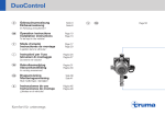
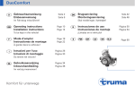
Duomatic L
50020 - 35300 · 02/98 · 5’B+W · ©
Gebrauchsanweisung Operating instructions Mode d’emploi
Installation instructions Instructions de montage
Einbauanweisung
Im Fahrzeug mitzuführen!
To be kept in the vehicle!
À garder dans le véhicule!
Seite 1
Page 3
Page 5
Service
Truma, Postfach 1252
D-85637 Putzbrunn
Telefon D-(0) 89/4617-142
Telefax D-(0) 89/4617-159
Duomatic L
A
4
3
1
3
5
B
6
7
10
8
9
11
2
50 cm
Duomatic L
Regler-Umschaltautomatik für die Zweiflaschen-Gasanlage mit
Fernanzeige, Sicherheitsventil, Manometer
und Eis-Ex
Gebrauchsanweisung
d
e
b
a
a = Aus
b = Ein (Sommerbetrieb)
c = Ein und Heizen
(Winterbetrieb)
d = Grüne Kontrolleuchte
e = Rote Kontrolleuchte
c
Inbetriebnahme
Gasflaschen immer senkrecht
stellen und gegen Umfallen
sichern (insbesondere 33 kgFlaschen)! Die Duomatic-Regler
sind mit Kombinationsanschluß
für die 3-, 5-, 11-, und 33-kg Flasche ausgestattet. Regler stets
so montieren, daß die grüne bzw.
rote Schutzkappe oben ist!
Schläuche nicht knicken oder
stark biegen!
Zuerst Ventil der Reserveflasche,
dann Ventil der Betriebsflasche
öffnen (beide Regler sind jetzt
entlüftet). Betriebsflasche kenntlich am grünen Regler - liefert Gas. Wenn diese leer bzw.
nicht mehr betriebsbereit ist, liefert die Reserveflasche (roter
Regler) automatisch das Gas. Bei
Verwendung von nur einer Gasflasche, ist der Betriebsregler
(grün) anzuschließen.
Sommerbetrieb:
Am Bedienteil den Drehknopf auf
„Sommer“ (b) stellen. Die
Leuchtdioden zeigen an, welche
der beiden Flaschen das Gas
liefert: grüne Leuchtdiode (d) =
Betriebsflasche, rote Leuchtdiode (e) = Reserveflasche.
Winterbetrieb:
Im Betriebsregler ist ein Eis-Ex
integriert. Dieser verhindert das
Einfrieren des Reglers und damit
Störungen der Gasanlage. Bei
Außentemperaturen um 0°C und
tiefer, Drehknopf auf „Winter“ (c)
stellen. Der Betriebsregler wird
jetzt beheizt und die Leuchtdioden
zeigen an welche Flasche Gas
liefert..
Flaschenwechsel
Ventil der Betriebsflasche schließen. Regler abschrauben.
(Achtung Gasrest: Nicht Rauchen
und keine offenen Flammen!).
Alle Gasgeräte können aus der
Reserveflasche (roter Regler) versorgt werden bzw. weiter in Betrieb bleiben! Volle Flasche an Betriebsregler anschließen (nur von
Hand, keine Werkzeuge verwenden - Linksgewinde) und Flaschenventil öffnen. Automatisch liefert
die Betriebsflasche wieder Gas.
Hinweis: Es empfiehlt sich, gelegentlich die Reserveflasche als
Betriebsflasche zu verwenden, um
sicherzustellen, daß die Reserveflasche immer ausreichend gefüllt
ist.
Leckprüfung
2. Flaschen- und Schnellschlußventile in der Gasleitung öffnen.
3. Druck ablesen und Flaschenventile schließen.
4. Zeigt das Manometer nach
10 Minuten immer noch den gleichen Druck, dann ist die Gasanlage dicht. Fällt der Druck ab,
dann ist die Gasanlage undicht
(Flaschendichtung, Verschraubung
oder Armatur defekt) und muß unverzüglich von einem Fachmann in
Ordnung gebracht werden.
Flaschenventile nicht mehr öffnen!
Sicherheitsventil
Die Duomatic-Regler sind mit
Sicherheitsventil ausgestattet, so
daß bei einem Defekt kein überhöhter Druck an die Geräte kommen kann.
Technische Daten
Spannung: 12 V
Betriebsdruck: 50 oder 30 mbar
Durchflußmenge
Betriebsregler: 1,5 kg/h
Reserveregler: 0,8 kg/h
Stromaufnahme
ohne Eis-Ex: 20 mA
mit Eis-Ex: 300 mA
DVGW-Prüfzeichen:
G 91 e 032 (50 mbar)
G 96 e 048 (30 mbar)
1. Alle Geräte abstellen.
1
Einbauanweisung
Achtung: Der Betriebsdruck der
Duomatic L (30 oder 50 mbar)
muß mit dem Betriebsdruck der
eingebauten Geräte übereinstimmen.
3. Schläuche (3) mit Schlüssel an
die Regler (4 + 5) anschrauben
(Linksgewinde!).
4. Regler an die Flasche anschließen - nur von Hand
(Linksgewinde!), keine
Werkzeuge verwenden!
Einbau und Reparatur der
Duomatic L darf nur vom
Fachmann durchgeführt werden.
Schläuche nicht knicken oder
stark biegen!
Verwendungszweck
1. Bild B: Platz für das Bedienteil
(6) an gut sichtbarer Stelle vorsehen. Loch Ø 8 mm für die Kabeldurchführung (7) bohren. Bedienteil mit den 2 beiliegenden Senkkopfschrauben 2,9 mm (8) befestigen und Drehknopf (9) aufsetzen.
Die Duomatic L ist nur zulässig
für Fahrzeuge mit Aufstellung der
Flaschen im Freien bzw. in
Schränken, die gegen den
Fahrzeug-Innenraum dicht ausgeführt und nur von außen zugänglich sind!
Achtung: Nicht in geschlossenen
Räumen (Haushalt) verwenden!
Anschluß der Regler
im Flaschenkasten
1. Bild A: T-Stück (1) auf das
Gasrohr (2) schrauben.
2. Die beiden Schläuche (3) an
die Rohrzapfen des T-Stückes (1)
anschließen.
2
Elektrischer Anschluß
Für die „Unterputz-Montage“
des Bedienteils liefert Truma als
Sonderzubehör einen Bedienteilrahmen (Art.-Nr. 39980-01).
2. Das 3-polige Anschlußkabel
des Druckschalters (10) mit
Isolierband parallel zum Gasschlauch (3) und Gasrohr (2) verlegen.
3. Kabel nach innen zum vorgesehenen Platz für das Bedienteil
verlegen und gemäß Anschlußschema an das 4-polige Anschlußkabel des Bedienteils (6)
anschließen.
Anschlußschema
braun
schwarz
6
braun
schwarz
blau
blau
rot
+
10
12 V
Achtung: Der Anschluß darf
nicht im Flaschenkasten erfolgen! Für Flaschenkasten-Durchführung (11) Gummitülle oder
Karosseriedichtmittel verwenden. Durchführung mindestens
50 cm über dem Boden des
Flaschenkastens - oder in einem
Schutzrohr verlegt - vorsehen.
Falls erforderlich, das 3-polige
Kabel 3 x 0,75 mm2 verlängern.
4. Gerät am abgesicherten Bordnetz (Zentralelektrik 5 - 10 A) mit
Kabel 2 x 0,75 mm2 anschließen.
Minusleitung an Zentralmasse.
Bei direktem Anschluß an die
Batterie ist die Plus- und
Minusleitung abzusichern.
Bei Verwendung von Netzteilen ist zu beachten, daß das
Gerät nur mit Sicherheitskleinspannung nach EN 60742 betrieben werden darf.
Die Duomatic L kann über den
Truma-Trafostecker (Art.-Nr. 5311001) auch mit 230 V betrieben werden. Der Trafostecker liefert 12 V
Wechselstrom mit geringer
Leistung. Die zwei Kabel am Trafostecker können beliebig angeklemmt werden (ein Anschluß von
weiteren 12 V-Geräten ist nicht
möglich).
Anschließend gemäß der
Gebrauchsanweisung sämtliche
Funktionen des Gerätes prüfen.
Die Gebrauchsanweisung ist
dem Betreiber auszuhändigen!
Duomatic L
Regulators with automatic switch-over for
gas installation with
two cylinders equipped with remote
distant indication,
safety valve, manometer and Eis-Ex
Operating
instructions
d
e
b
a
a = off
b = on (summer operation)
c = on and heating
(winter operation)
d = green indicator lamp
e = red indicator lamp
c
Operating
Always stand the gas cylinders
in upright position and secure
against tipping over (particularly
the 33-kg cylinders). The Duomatic
regulators have a combination
connection fitting for the 3-kg, 5kg, 11-kg and 33-kg cylinders.
Always assemble the regulators in
such a way that the green or red
safety caps are facing upwards!
Do not kink or severely bend the
hoses!
First open the valve of the reserve
cylinder and then open the valve
of the operating cylinder (both
regulators are now vented). The
operating cylinder (marked with a
green regulator) supplies the appliances with gas. When it is empty
or no longer ready for operation,
the reserve cylinder (red regulator)
supplies the gas automatically. If
using just one gas cylinder,
connect the operating regulator
(green).
Summer operation:
Turn the control knob of the control panel to „summer“ (b). The
LED’s indicate which of the two
cylinders is supplying the gas:
green LED (d) = operating cylinder, red LED (e) = reserve cylinder.
Winter operation:
An Eis-Ex is integrated in the operating regulator which prevents
freezing of the regulator and accordingly disturbances in the operation of the gas system. In case of
outside temperatures around 0°C
and lower, set the control knob of
the control panel to „winter“ (c),
the operating regulator is now heated in addition to indicating the
cylinder in operation.
Changing cylinders
Close the valve at the operating
regulator. Unscrew regulator.
(Caution residual amount of gas:
Do not smoke and no open flames!)
All gas appliances can be supplied
with gas from the reserve cylinder
(red regulator) or they remain in
operation! Connect full cylinder to
operating regulator (only tighten
by hand, do not use a tool - lefthand thread) and open cylinder
valve. The operating cylinder automatically takes over the gas supply
again.
Note: We recommend using the
reserve cylinder as operating cylinder every now and again, to make
sure the reserve cylinder still has a
sufficient gas supply.
Checking for leaks
1. Switch off all appliances.
2. Open cylinder and quickacting valves in the gas line.
3. Read off pressure and close
cylinder valves.
4. If the pressure gauge indicates the same pressure after 10
minutes, there are no leaks in
the gas system. If the pressure
drops, the gas system is leaking (defective cylinder gasket,
screw connection or fittings) and
must be repaired by an expert
straight away. Do not open
cylinder valves again!
Safety valve
The Duomatic regulators are
equipped with a safety valve
which prevents excessive pressure developing in the appliances if there is a defect.
Technical Data
Voltage: 12 V
Operating pressure:
50 or 30 mbar
Rate of flow
Operating regulator: 1,5 kg/h
Reserve regulator: 0,8 kg/h
Current input
without Eis Ex: 20 mA
with Eis Ex: 300 mA
DVGW approval mark:
G91 e 032 (50 mbar)
G96 e 048 (30 mbar)
3
Installation
instructions
3. Screw the gas hoses (3) to the
regulators (4 + 5) with a spanner
(left-hand thread!).
Attention: The operating pressure of the Duomatic L (30 or
50 mbar) must correspond to
the installed appliances!
4. Screw regulators to the gas
cylinders - only tighten by hand
(left-hand thread!) do not use a
tool!
The installation and repair is
only to be installed and repaired by an expert.
Do not kink or severely bend
the hoses.
Application
The Duomatic L is only approved
for vehicles where the gas cylinders are mounted on the outside
of the vehicle or in closets which
are sealed off from the inside of
the vehicle and are only accessible from the outside!
Attention: Do not install in closed areas (domestic households)!
Connection of the
regulators in the gas
cylinder compartment
1. Fig. A: Screw T-piece (1) to the
gas pipe (2).
2. Screw the two gas hoses (3)
to the T-piece (1).
4
Electrical connection
1. Fig. B: The place for the control panel (6) is to be in a position
which is easy to view. Drill a hole
with 8 mm diameter for passing
the cable through (7). Fix the control panel (8) with the 2 screws
2,9 mm (9) and replace the rotary
control knob.
For „concealed assembly“ of the
control panel there is a control
panel frame available from Truma
as special equipment (art. no.
39980-01).
2. Route the 3-pole connecting
cable of the pressure switch (10)
with insulating tape parallel to the
gas hose (3) and gas pipe.
3. Route cable to the inside to
the place where the control panel
is to be installed and connect
control panel (6) as shown in the
connecting diagram to the 4-pole
connecting cable.
Connection diagram
brown
6
If using power packs make sure
that the appliance can only be
operated with safety extra-low
voltage in accordance with EN
60742.
brown
black
black
blue
blue
10
red
+
12 V
Attention: The connection is
not to be in the cylinder compartment! For the cylinder compartment opening use a rubber sleeve or body sealing compound.
The leadthrough opening must
be at least 50 cm above the floor
of the cylinder compartment - or
routed insed a cable conduit.
Lengthen using a 3 x 0,75 mm2
cable, if necessary.
4. Connect appliance to fused
vehicle power supply (central
electrical system 5 - 10 A) using
a cable 2 x 0,75 mm2. The negative lead is to be connected to the
central ground. When connecting
directly to the battery, always
fuse the positive and negative
lead.
With the Truma transformer
connector (art. no. 53110-01) The
Duomatic L can also be operated
with 230 V. The transformer
connector supplies a 12 V alternating current with low power. The
two cables on the transformer
connector can be connected in
any order (it is not possible to
connect any other 12 V appliances)
Finally check all functions of the
appliance as specified in the operating instructions.
The operating instructions
must be handed to the user.
Duomatic L
Commutation automatique de réserve,
complet avec téléaffichage, soupape de
sécurité, manomètre
et dispositif de dégivrage Eis-Ex
Mode d’emploi
d
e
b
a
a = Arrêt
b = Marche (service d’été)
c = Marche et chauffage
(service d’hiver)
d = Lampe-témoin verte
e = Lampe-témoin rouge
c
Mise en service
Toujours placer les bouteilles verticalement et les préserver des accidents (surtout les bouteilles de 33 kg)!
Les détendeurs Duomatic sont dotés
de raccords combinés pour les bouteilles de 3, 5, 11 et 33 kg. Toujours monter les détendeurs de telle sorte que
les capuchons de protection verte ou
rouge soient en haut! Ne pas couder
les flexibles ni les cintrer trop fortement!
Ouvrir d’abord le robinet de la bouteille
de réserve, puis le robinet de la bouteille de service (les deux détendeurs
sont alors purgés). La bouteille de service - reconnaissable au détendeur vert
- fournit du gaz. Si celle-ci est vide ou
n’est plus en service, la bouteille de
réserve (détendeur rouge) fournit automatiquement le gaz. Si on n’utilise
qu’une bouteille, il faut raccorder le
détendeur de service.
Service d’été
Mettre le bouton de réglage de la
pièce de commande sur la position
„été“ (b). La diode électroluminescente montre laquelle des deux bouteilles
fournit le gaz: diode électroluminescente verte (d) = bouteille de service,
diode électroluminescente rouge (e) =
bouteille de réserve.
Service d’hiver
Dans le détendeur de service le dispositif de dégivrage Eis-Ex est intégré.
Celui-ci évite le givrage du détendeur
et donc des défauts de fonctionnement de l’installation à gaz. En cas de
température extérieure égale ou
inférieure à 0°C, mettre le bouton de
réglage de la pièce de commande sur
la position „hiver“ (c). Tout comme
l’affichage, le détendeur de service
est maintenant chauffé.
Changement
de bouteille
Fermer le robinet de la bouteille de
service (Attention restes de gaz: Ne
pas fumer et pas de flammes nues).
Tous les appareils à gaz peuvent être
alimentés depuis la bouteille de réserve (détendeur rouge) et donc rester
en service! Raccorder une bouteille
pleine au détendeur de service et
ouvrir le robinet de la bouteille (ne les
serrer qu’à la main, sans utiliser
d’outil - filet à gauche)! La commutation s'effectue automatiquement, et le
gaz est de nouveau fourni par la bouteille de service.
Nota: Il est recommandé d’utiliser de
temps en temps la bouteille de réserve comme bouteille de service, pour
assurer que la bouteille de réserve
soit toujours suffisamment remplie.
Contrôle d’étanchéité
les robinets à fermeture rapide dans la
conduite de gaz.
3. Lire la pression et refermer les robinets des bouteilles.
4. Si, au bout de 10 minutes, le manomètre continue d’afficher la même
pression, l’installation est étanche. Si
la pression s’abaisse, l’installation à
gaz n’est pas étanche (joints d’une
bouteille, union vissée ou robinet
défectueux) et doit être réparée sans
retard par un spécialiste. Ne plus
ouvrir les robinets des bouteilles!
Soupape de sécurité
Les détendeurs Duomatic sont dotés
d’une soupape de sécurité, afin qu’en
cas de défaut, le gaz ne puisse pas
arriver aux appareils à une pression
excessive.
Caractéristiques
techniques
Tension: 12 V
Pression de service: 50 ou 30 mbar
Débit
Détendeur de service: 1,5 kg/h
Détendeur de réserve: 0,8 kg/h
Consommation de courant
sans Eis-Ex: 20 mA
avec Eis-Ex: 300 mA
Estampille de contrôle DVGW:
G 91 e 032 (50 mbar)
G 96 e 048 (30 mbar)
1. Eteindre tous les appareils.
2. Ouvrir les robinets des bouteilles et
5
Instructions
de montage
3. Visser les flexibles (3) aux détendeurs (4 + 5) à l’aide d’une clef (filet
à gauche).
Attention: La pression de service du
Duomatic L (30 ou 50 mbar) doit
être conforme à la pression de service des appareils montés !
4. Raccorder les détendeurs aux bouteilles (filet à gauche) - ne les serrer
qu’à la main, sans utiliser d’outil!
Le montage et les réparations du
Duomatic L ne doivent être effectués que par un spécialiste.
Utilisation
Le Duomatic L n’est agrée que pour
des véhicules sur lesquels les bouteilles de gaz sont logées à l’extérieur ou
dans des armoires étanches par rapport à l’habitacle et accessibles de
l’extérieur seulement !
Attention: Ne pas couder les
flexibles ni les cintrer trop
fortement!
Raccordement des
détendeurs dans le
caisson à bouteilles
1. Fig. A: Visser la pièce en T (1) sur
la conduite de gaz (2).
2. Raccorder les deux flexibles (3) aux
tenons de la piéce en T (1).
6
Ne pas couder les flexibles ni les
cintrer trop fortement!
Branchement
électrique
1. Fig. B: Prévoir pour la pièce de
commande (6) un emplacement bien
visible. Percer un trou de Ø 8 mm
pour faire passer le câble (7). Fixer la
pièce de commande avec les 2 vis à
tête fraisée 2,9 mm (8) jointes et
poser ensuite le bouton de réglage
(9).
Pour un montage encastré de la
pièce de commande, Truma livre un
cadre de pièce de commande (n° de
réf. 39980-01) comme accessoire
spécial.
2. Avec un ruban isolant, installer le
câble de branchement à 3 fils du
manocontacteur (10) parallèlement au
flexible de gaz (3) et à la conduite de
gaz (2).
3. Installer le câble vers l’intérieur jusqu’à l’emplacement prévu pour la
pièce de commande et le raccorder
au cable à 4 pôles de la pièce de
commande (6) selon le schéma de
branchement.
Schéma de
branchement
marron
6
marron
noir
noir
bleu
bleu
10
rouge
lisée, il faut observer que l’appareil
ne doit être branché qu’à une petite
tension de sécurité selon EN 60742.
Moyennant la fiche à transformateur
intégré Truma (n° de ref. 53110-01),
le Duomatic L peut aussi être utilisé
sur 230 V. La fiche à transformateur
fournit du courant alternatif 12 V de
faible puissance. Les deux fils de
branchement à la fiche peuvent être
branchés de façon quelconque (le
branchement d’autres appareils en
12 V n’est pas possible).
+
12 V
Attention: Le branchement ne doit
pas s’effectuer dans le caisson à bouteille! Pour traverser la paroi du caisson (11), utiliser un passe-fil ou du
mastic d’étanchéite pour carrosseries.
Prévoir le passage à 50 cm au moins
au-dessus du fond du caisson à bouteille ou installer le fil dans un tuyau
de protection. Si nécessaire rallonger
le câble à 3 pôles 3 x 0,75 mm2.
4. Brancher l’appareil protégé par un
fusible (installation électrique centrale
5 - 10 A) au réseau de bord avec un
câble de 2 x 0,75 mm2. Brancher le fil
moins à la masse centrale. En cas de
branchement direct à la batterie,
protéger les fils plus et moins.
Si on utilise une alimentation stabi-
Ensuite, contrôler toutes les fonctions de l’appareil selon le mode
d’emploi.
Remettre le mode d’emploi à l’utilisateur!