1
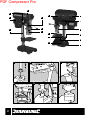
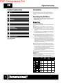
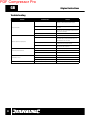
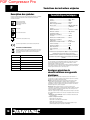
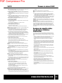
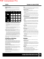
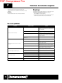
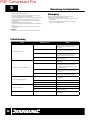
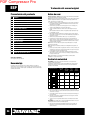
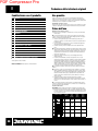
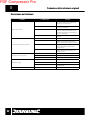
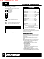
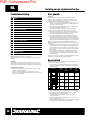
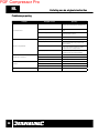
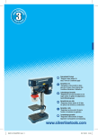
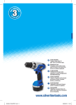
PDF Compressor Pro
GB
Product Familiarisation
Original Instructions
Intended Use
1
Column
2
Motor
3
On/Off Switch
4
Pulley Cover
5
Drilling Depth Gauge
6
Chuck Guard
7
Chuck
8
Spindle Pulley
Before Use
9
Motor Pulley
Assembling Your Drill Press
10
Drive Belt Tension Adjuster
11
Plunge Handles
12
Table Locking Handle
13
Table
14
Base
15
Base Holes
16
Table Tilt Angle Scale
17
Table Tilt Bolt (hidden)
Accessories included:
Hex key & chuck key
Bench mounted vertical drill for drilling a wide range of materials excluding most
masonry materials. Enables precise control of depth, hole position and angle entry into
the workpiece. Provides a stable platform when using accessories compatible with a
normal chuck.
Unpacking Your Drill Press
• Ensure that all parts of your drill press are present and in good condition.
If any part is missing, or damaged, have such parts replaced before
attempting to use this tool
Tools required for assembly and operating (not included): Phillips screwdriver & Spanner
<moved>
Note: This product will have traces of oil and grease on its component parts to protect
against corrosion. Clean off such residue before assembly especially the chuck mounting
and the internal fitting of the Chuck (7).
1. Secure the Column (1) to the Base (14) using the supplied bolts (x3), spring washers
(x3) and washers (x3) included. The spring washers fit between the bolt head and the
washer (Fig. A)
2. Slide the Table (13) on to the Column (1) and tighten the Table Locking Handle (12)
when approximately 150mm from the base (Fig. B)
3. Place the drill press head assembly on to the Column and lower it as far as it will go
Note: Seek assistance when handling the drill press head assembly as it is heavy.
4. When the head is aligned to the base, tighten the 2 hex grub screws which hold the
drill press head assembly in place with the supplied Hex key (Fig. C). These hex grub
screws are directly below The Drive Belt Tension Adjuster (10) on the same side
5. Screw the three Plunge Handles (11) into the Plunge Handles mounting (Fig. D)
6. The chuck fits using a simple Morse taper connection and relies on the friction of the
surfaces to hold the chuck in position. Fit the chuck to the chuck mounting by placing
a small piece of wood below the chuck and operate the Plunge Handles to lower the
chuck mounting to fit the Chuck (Fig. E). You can alternatively fit the chuck before
mounting the drill press head assembly on the column. If necessary use a soft mallet
to help secure the Chuck but only use light force
Note: It is essential both surfaces are free of oil and grease for the chuck to be secure.
Note: Make sure the chuck jaws are recessed before striking the chuck with a mallet.
7. Angle the Chuck Guard(6) so you can remove the screws (x3), washers (x3) and nuts
(x3) that are pre-fitted to the chuck guard that will secure the chuck guard visor. Fit
the visor (Fig. F) and then loosely re-assemble the screws, washers and nuts in each
hole. Ensure the visor position is correct then tighten the fittings.
8. It is important to secure the drill press to a work surface to prevent the tool tipping
over. Fit bolts and nuts (not provided) through the Base Holes (15) and matching holes
through a work surface to secure the drill press
Note: If you don’t secure the drill permanently it is recommended to use clamps to secure
the tool to a work surface or work only with material too small to cause the drill to tip over.
Adjusting speed
IMPORTANT: The drill may need adjustment of the Drive Belt Tension Adjuster (10) before
use even if you use the gear already set.
• The drill has 5 speeds which are manually set. See chart below showing belt positions
for each speed plus an approximate speed guide for type and size of drill bit.
Belt Position
6
Speed
(min-1)
Spiral
drill bit
(metal)
Bradpoint
drill bit
(wood)
Forstner
bit (wood)
8
9
600
11 - 13mm
>25mm
35 - 50mm
8
9
900
8 - 10mm
25mm
28 - 32mm
8
9
1250
5 - 7mm
20mm
19 - 25mm
8
9
1750
3 - 4mm
3-15mm
13 - 16mm
8
9
2600
1-2mm
<16mm