1
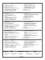
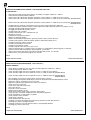
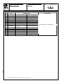
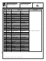
Indice
1.
2.
2.1
2.2
2.3
3.
3.1
4.
4.1
4.2
5.
Dati tecnici
Istruzioni d'uso provagiochi
Identificazione dei comandi e loro funzione
Spiegazione utilizzo provagiochi
Uso del comando provagiochi per illuminazione
Installazione
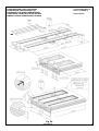
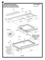
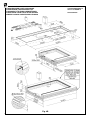
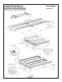
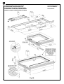
Preparazione dell’area di installazione - ponti ad incasso
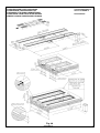
Posizionamento delle pedane e collegamento
dell’impianto idraulico in posizione standard
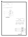
RAV635 IMOT4 - RAV650 IMOT4 - IMOT7
RAV635 MOT4 - RAV650 MOT4 - MOT7
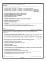
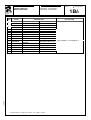
Contents
1.
2.
2.1
2.2
2.3
3.
3.1
4.
4.1
4.2
5.
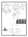
Fitting the limit switch FC2, solenoid valve connections
and pressure gauges
6.
Expelling the air and synchronizing the basements
7.
Securing the lift to the ground and checking alignment
of platforms (recessed versions)
7.1 Checking base levelness
8.
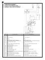
HYDRAULIC SYSTEM DIAGRAM
9.
Installation and periodic inspections
10. Spare parts
10.1 How to order spare parts
10.2 Spare parts summary
Technical data
Play detector instructions for use
Identifying the controls and their function
How to use the play detector
Using the play detector control for lighting
Installation
Preparing the installation area - recessed lift
Positioning the platforms and connecting the
hydraulic system in standard position
RAV635 IMOT4 - RAV650 IMOT4 - IMOT7
RAV635 MOT4 - RAV650 MOT4 - MOT7
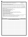
Inhalt
1.
2.
2.1
2.2
2.3
3.
3.1
4.
4.1
4.2
5.
Montage Endschalter FC2, Anschluss
Elektroventile und Druckwächter
6.
Entlüftung und Fahrschienensynchronisierung
7.
Befestigung der hebebüne am boden und
ebenheitskontrolle der anreihung (Einbauversion)
7.1 Ebenheitskontrolle des Untergestells
8.
SCHALTPLAN ÖLDYNAMISCHE ANLAGE
9.
Kontrollen der erstinstallation und regelmässige
kontrollen
10. Ersatzteile
10.1 Anweisungen für Ersatzteilbestellungen
10.2 Tafelverzeichnis
Technische Daten
Bedienungsanleitung - gelenkspieltester
Steuerungen und deren Funktion
Einsatz des Gelenkspieltesters
Einsatz der Gelenkspielsteuerung für die Beleuchtung
Aufstellung
Vorbereitung der Montagezone - Unterflur-Hebebühnen
Positionierung der Fahrbahnen und Anschluss der
Hydraulikanlage in Standardposition
RAV635 IMOT4 - RAV650 IMOT4 - IMOT7
RAV635 MOT4 - RAV650 MOT4 - MOT7
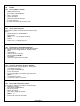
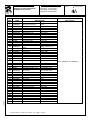
Index
1.
2.
2.1
2.2
2.3
3.
3.1
4.
4.1
4.2
Montaggio finecorsa FC2, collegamento
elettrovalvole e pressostati
6.
Spurgo aria e sincronizzazione pedane
7.
Fissaggio a terra del sollevatore e controllo
allineamento pedane (versione ad incasso)
7.1 Controllo planarità basi
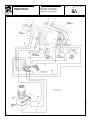
8.
SCHEMA IMPIANTO OLEODINAMICO
9.
Verifiche di installazione e periodiche
10. Ricambi
10.1 Come richiedere i ricambi
10.2 Indice tavole ricambi
5.
Spécifications techniques
Instructions d’exploitation de la plaque à jeux
Identification des commandes et de leurs fonctions
Explication utilisation plaque à jeux
Utilisation de la commande plaque à jeux pour l’éclairage
Installation
Préparation de la zone d’installation – versions
encastrées
Positionnement des chemins de roulement et
connexion de l’installation hydraulique dans la position
standard
RAV635 IMOT4 - RAV650 IMOT7 - IMOT7
RAV635 MOT4 - RAV650 MOT4 - MOT7
Installation de l’interrupteur FC2, connexion des
électrovalves et des pressostats
6.
Purge de l’air et synchronisation des chemins de
roulement
7.
Fixation du pont elevateur au sol et controle de la
alignement des chemins de roulement (version
encastrée)
7.1 Contrôle planéité des bases
8.
SCHEMA DE L’INSTALLATION OLEODYNAMIQUE
9.
Contrôles à realiser lors de l'installation et
periodiquement
10. Pièces détachées
10.1 Comment commander des pièces détachées
10.2 Sommaire planches
Índice
1.
2.
2.1
2.2
2.3
3.
3.1
4.
4.1
4.2
Datos técnicos
Instrucciones de uso detector de holguras
Identificación de mandos y su función
Explicación sobre el uso del detector de holguras
Uso del mando detector de holguras para iluminación
Instalación
Preparación del área de instalación – elevadores empotrados
Posicionamiento de las plataformas y conexión del
sistema hidráulico en posición estándar
RAV635 IMOT4 - RAV650 IMOT4 - IMOT7
RAV635 MOT4 - RAV650 MOT4 - MOT7
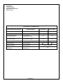
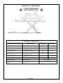
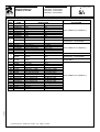
COMPOSIZIONE
DEL MANUALE
COMPOSITION OF
MANUAL
56 pagine (copertine 56
comprese)
pages (including
cover pages)
5.
Montaje del microinterruptor de tope FC2,
conexión de las electroválvulas y presóstatos
6.
Purga aire y sincronización plataformas
7.
Fijación al piso del elevador y control alineacion
plataformas (modelo empotrado)
7.1 Control nivelación de las bases
8.
ESQUEMA DE LA INSTALACIÓN OLEODINÁMICA
9.
Controles de instalación y periódicos
10. Repuestos
10.1 Cómo pedir las piezas de repuesto
10.2 Índice tablas
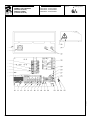
ZUSAMMENSETZUNG COMPOSITION DE LA COMPOSICIÓN
NOTICE
MANUAL
DER ANLEITUNG
56 Seiten (inkl.
Deckblätter)
0586-M003-0
56 pages (pages de
la couverture incluses)
DEL
56 páginas (incluidas
las portadas)
3