1
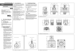
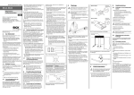
OPERATING INSTRUCTIONS UE232MF Safety relays en SICK AG • Industrial Safety Systems Erwin-Sick-Straße 1 D-79183 Waldkirch • www.sick.com 8015185/XR91/2013-10-29 • TF_2M Printed in Germany (2013-10) • All rights reserved • Subject to change without notice 1 Scope These operating instructions are only applicable to the UE232MF safety relays with the following entry on the type label in the field Operating Instructions: 8015185 You will find the device’s date of manufacture on the type label in the field Date Code in the format yywwxxxx (yy = year, ww = calender week, xxxx = serial number). These operating instructions are original operating instructions. 2 The related actuators on the machine or system can be safely shut down using the safety relay’s output signal switching contacts. The UE232MF safety relay is used only for safety sensors with volt-free output contacts or safety switches, e.g. emergency stop pushbuttons (EN ISO 13850): single- or dual-channel, e.g. SICK ES21 safety interlocks (EN 1088): single- or dualchannel, e.g. safety doors safety circuits in accordance with EN 602041, e.g. for moving covers 3 2.3 3.2 On safety Qualified safety personnel The UE232MF safety relay must only be installed, commissioned and serviced by qualified safety personnel. Qualified safety personnel are defined as persons who … have undergone the appropriate technical training and have been instructed by the responsible machine operator in the operation of the machine and the current valid safety guidelines and have access to the operating instructions of the UE232MF safety relay and have read and familiarized themselves with them. 2.2 Applications of the device The UE232MF safety relay can be used: in accordance with EN ISO 13849 up to PL d and category 3 in accordance with EN 62061 to SILCL2 The actual performance level or SIL claim limit achieved depends on the external circuit, the design of the wiring, the selection of the control switch and its placement on the machine. The UE232MF safety relay has been evaluated to UL 508. The inputs on the UE232MF safety relay are prepared for the connection of the safety sensors listed in section 2.2 “Applications of the device”. Operation (input circuit) is by means of the supply voltage. The two enable current paths are designed as safe outputs. The signaling current path is not a safe output. 2.5 Pay attention to the safety notes and protective measures! Please observe the following items in order to ensure the correct use of the UE232MF safety relay. During the mounting, installation and usage of the safety relay, observe the standards and directives applicable in your country. The national/international rules and regulations apply to the installation, commissioning, use and periodic technical inspection of the safety relay, in particular: – the Machinery Directive 2006/42/EC – Work Equipment Directive 2009/104/EC – EMC directive 2004/108/EC – the work safety regulations and safety rules Manufacturers and operators of the machine on which a safety relay is used are responsible for obtaining and observing all applicable safety regulations and rules. The tests must be carried out by qualified safety personnel or specially qualified and authorized personnel and must be recorded and documented to ensure that the tests can be reproduced and retraced at any time by third parties. The operating instructions must be made available to the operator of the machine where the UE232MF is used. The machine operator is to be instructed in the use of the device by qualified safety personnel and must be instructed to read the operating instructions. Environmental protection Disposal of unusable or irreparable devices must always occur in accordance with the applicable country-specific waste-disposal regulations (e.g. European Waste Code 16 02 14). In order to attain SILCL2/PL d, connect the external device monitoring! In order to reach SILCL2/PL d, an external diagnosis with DC ≥ 99% must be applied (i.e. the external device monitoring must be connected). Please also read the notes in chapter 12 “Application examples”. Status indicators Display Meaning SUPPLY Green K1, K2 Green Supply voltage active Channel 1, 2 switched See also section 7 “Error messages of the SUPPLY LED”. 4 Mounting Mounting only with enclosure rating IP 54 or better! The safety relay is only allowed to be mounted in the control cabinet. The control cabinet must at least comply with enclosure rating IP 54. Mounting according to EN 50274. The modules are located in a 22.5 mm wide modular system for 35 mm mounting rails as per EN 60715. 5 5.1 Electrical installation Switch the entire machine/system off line! All connections and wiring must comply with the required category as per EN ISO 13849 and EN 62061. The output signal switching devices and the external device monitoring (EDM) must be wired in the control cabinet. To prevent the welding of the contacts on the built-in relay, an overcurrent protection device with short-circuit protection (duty class gG) in accordance with the related usage category is to be selected and integrated into the enable current paths (seeFig. 3, fuse F2/F3). Only with UE232MF2Ax: In case of problems due to interference, if necessary connect FE to a low-noise earth. Pay attention to EMC-compliant wiring! Cables (A1/A2) are to be laid such that external noise cannot prevent shut down. Terminal assignment Terminal A1 A2 Y1–Y2 Y1–Y3 13–14 23–24 31–32 Device functions Opening of the input circuits results in the opening of the enable current paths and the closing of the signaling current path. Manual or automatic reset as well as external device monitoring are to be implemented using external wiring as required (see 5.3 “Reset” and 5.4 “External device monitoring”). 2.4 General safety notes and protective measures This chapter deals with your own safety and the safety of the system operators. Please read this chapter carefully before working with the UE232MF or with the machine protected by the UE232MF. 2.1 Correct use The UE232MF safety relay must be used only as defined in section 2.2 “Applications of the device”. It must be used only by qualified safety personnel and only on the machine where it has been installed and initialized by qualified safety personnel in accordance with the operating instructions. If the device is used for any other purposes or modified in any way — also during mounting and installation — any warranty claim against SICK AG shall become void. Product description 3.1 Structure and operating principle of the device 5.2 Description Voltage supply UB+/L1 Voltage supply GND/N– Automatic reset Manual Reset Enable current path 1 Enable current path 2 Signaling current path (not safe) Connection facilities Single-channel operation The safety sensor is connected between L+ and A1 (see Fig. 4). Dual-channel operation One volt-free switching element on the safety sensor is to be connected between L+ and A1, the second element is to be connected between A2 and N– (see Fig. 5). 5.3 Reset Check the hazardous area! Ensure there is nobody in the hazardous area before commissioning. Secure the hazardous area against entry. Regular inspection of the protective devices by qualified safety personnel Check the system following the inspection intervals specified in the national rules and regulations. – Each safety application must be checked at an interval specified by you. – The effectiveness of the protective devices must be checked daily by a specialist or by authorized personnel. If changes have been made to the machine or the protective device, or the safety relay has been changed or repaired, you must again thoroughly check the entire safety application. 7 Error messages of the SUPPLY LED Display Meaning No supply voltage or undervoltage or cross circuit on A1/A2 No error, device ready for operation Cross circuit on the RESET inputs RESET error Overvoltage Internal error/serious error Green Manual reset The reset button (N/O contact) is to be connected to the terminals Y1 and Y3. The reset button is to be installed outside the hazardous area such that it cannot be pressed from inside the hazardous area. When operating the reset button, the operator must have full visual command of the hazardous area. The reset is monitored. For emergency switching off applications, a manual reset is to be used. 8 Automatic reset A wire jumper is to be connected between Y1 and Y2. Cease operation if the cause of the malfunction has not been clearly identified! Stop the machine if you cannot clearly identify or allocate the error and if you cannot safely rectify the malfunction. Complete function test after rectification of fault! After rectifying a fault, perform a complete function test. 5.4 Automatic reset Connect the contacts for the external device monitoring to Y1 and Y2. Green (3×) Green (6×) Green (flashing quickly) External device monitoring The external device monitoring for the actuators integrated is only effective on reset. The connection of the N/C contacts for the contact elements operated in series with the reset circuit provides this external device monitoring. Manual reset Connect the contacts for the external device monitoring in series with the reset button (Terminals Y1 and Y3). 6 Green (2×) Commissioning and regular tests Commissioning requires a thorough check by qualified safety personnel! Before you operate a system protected by the safety relay for the first time, make sure that the system is first checked and released by qualified safety personnel. Please read the notes in chapter 2 “On safety”. Observe the relevant laws and national regulations. 9 In the event of faults or errors 10 Conformity Type: Safety relays UE232MF The following manufacturer herewith declares that the product is in conformity with the provisions of the following EC directive(s), and that the respective standards have been applied. SICK AG, Erwin-Sick-Straße 1 D-79183 Waldkirch, Germany Date: 03.05.2012 Person empowered to draw up the technical documentation: Georg Plasberg Management Board Directives used: Machinery Directive 2006/42/EC EMC directive 2004/108/EC Standards used: EN 6094751 EN ISO 138491 EN 62061 EN 602041 EN 6132631 EN 55011 Notified body: Prüf- und Zertifizierungsstelle im BGPRÜFZERT, Gustav-Heinemann-Ufer 130, 50968 Köln, Germany ID number for the notified body: 0340 EC-type examination certificate number: ET 12031 You will find the signed EC declaration of conformity at: www.sick.com. Search for: 9181043 11 Internal circuitries Fig. 1: Internal circuitry UE232MF (DC version) Ordering information Part UE23-2MF for 24 V DC with screw type terminals UE23-2MF for 115120 V AC with screw type terminals UE23-2MF for 230 V AC with screw type terminals Part number (type code) 6026146 (UE23-2MF2D3) 6026147 (UE23-2MF2A4) 6026148 (UE23-2MF2A3) Fig. 2: Internal circuitry UE232MF (AC versions)