1
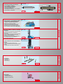
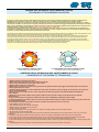
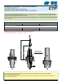
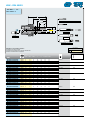
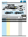
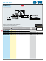
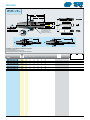
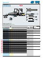
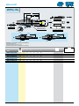
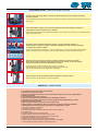
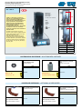
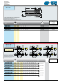
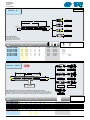
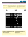
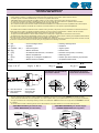
EW
S
N
3
7/
20
FORATURA
DRILLING
MASCHIATURA
TAPPING
ALESATURA
BORING
RADDRIZZATURA
STRAIGHTENING
STESSO INGOMBRO PER ARTICOLI DI
MASCHIATURA - FORATURA - ALESATURA - RADDRIZZATURA
SAME OVERALL SIZE FOR
TAPPING - DRILLING - BORING - STRAIGHTENING ITEMS
CTP
L min
L max
FLESSIBILITÁ IN LUNGHEZZA CON MANDRINI TIPO “CTP”
FLEXIBILITY IN LENGTH WITH CHUCK TYPE “CTP”
Prolunga Risultante Modificata
Resulting Modified Extension
Parte Prolunga Standard
Standard Extension Part
Mandrino Risultnte Modificato
Resulting Modified Chuck
Parte Mandrino Standard
Standard Chuck Part
2-3xØD2
ØD2
POSSIBILITÁ DI MODIFICA DEI MANDRINI
POSSIBILITY TO MODIFY THE CHUCKS
REFRIGERAZIONE INTERNA
INTERNAL COOLING
INFO
IL SISTEMA DEL CALETTAMENTO A CALDO
- SHRINK-FIT-SYSTEM
- SCHRUMPFVERBINDUNGSSYSTEM
- LE SYSTÈME À EMBOîTEMENT THERMIQUE
HSK - DIN 69893-A
MANDRINO A CALETTAMENTO TERMICO
- SHRINKING-ON TAPER SHANKS
- WERKZEUGAUFNAHMEN MIT
SCHRUMPFVERBINDUNG
- MANDRIN à EMBOÎTEMENT THERMIQUE
i info
HKA. ... .CT...
PAG 6÷9
DIN 69882-8
PAG 10
MANDRINO A CALETTAMENTO TERMICO
PROLUNGABILE
- EXTENSIBLE SHRINK FIT
- VERLÄNGERBARES SCHRUMPFFUTTER
- MANDRIN PROLONGEABLE à EMBOîtement
THERMIQUE.
PAG 11
SKB. ... .CT..
...... /A - AD - B
DIN 69871
MANDRINO A CALETTAMENTO TERMICO
PROLUNGABILE
- EXTENSIBLE SHRINK FIT
- VERLÄNGERBARES SCHRUMPFFUTTER
- MANDRIN PROLONGEABLE à EMBOîtement
thermique.
DIN 1835 A - DIN 6535 HA
DIN 1835 A - DIN 6535 HA
PAG 12
DIN 69882-8
MAS 403 BT-A-B
MANDRINO A CALETTAMENTO TERMICO
- SHRINKING-ON TAPER SHANKS
- WERKZEUGAUFNAHMEN MIT
SCHRUMPFVERBINDUNG
- MANDRIN à EMBOîtement THERMIQUE
PAG 14
BTB. ... .CT..
...... /A - AD - B
MANDRINO A CALETTAMENTO TERMICO
PROLUNGABILE
- EXTENSIBLE SHRINK FIT
- VERLÄNGERBARES SCHRUMPFFUTTER
- MANDRIN PROLONGEABLE à EMBOîtement
thermique.
SKB.40.CT F..
...... /A - AD - B
DIN 1835 A - DIN 6535 HA
DIN 1835 A - DIN 6535 HA
PAG 15
DIN 69882-8
BTB. ... .CTP..
...... /A - AD - B
CIL...
CIL..CTP..W
PAG 17
MANDRINO A CALETTAMENTO TERMICO
BTA.040.CT F..
DI FINITURA-INGOMBRO RIDOTTO
...... /A - AD
- SHRINK FIT FOR FINISHING-REDUCED
DIMENSIONS.
- SCHRUMPFFUTTER ZUM SCHLICHTEN KLEINER PLATZBEDARF
- MANDRIN POUR FINISSAGE à EMBOîtement
THERMIQUE-ENCOMBREMENT RéDUIT.
253...W
CIL..MF..W - CIL..MD..W
PAG 16
CIL...
CIL..CTP..W
MANDRINO A CALETTAMENTO TERMICO
SKA.40.CT F..
DI FINITURA-INGOMBRO RIDOTTO
...... /A - AD
- SHRINK FIT FOR FINISHING-REDUCED
DIMENSIONS.
- SCHRUMPFFUTTER ZUM SCHLICHTEN KLEINER PLATZBEDARF
- MANDRIN POUR FINISSAGE à EMBOîtement
THERMIQUE-ENCOMBREMENT RéDUIT.
SKB. ... .CTP..
...... /A - AD - B
253...W
CIL..MF..W - CIL..MD..W
PAG 13
CIL...
CIL..CTP..W
MANDRINO A CALETTAMENTO TERMICO
HKA. 063 CT F..
DI FINITURA-INGOMBRO RIDOTTO
- SHRINK FIT FOR FINISHING-REDUCED
DIMENSIONS.
- SCHRUMPFFUTTER ZUM SCHLICHTEN KLEINER PLATZBEDARF
- MANDRIN POUR FINISSAGE à EMBOîtement
THERMIQUE-ENCOMBREMENT RéDUIT.
MANDRINO A CALETTAMENTO TERMICO
- SHRINKING-ON TAPER SHANKS
- WERKZEUGAUFNAHMEN MIT
SCHRUMPFVERBINDUNG
- MANDRIN à EMBOîtement THERMIQUE
HKA. ... .CTP..
DIN 1835 A - DIN 6535 HA
CIL..MF..W - CIL..MD..W
PAG 18
253...W
DIN 1835 A - DIN 6535 HA
PROLUNGA IN ACCIAIO CON ATTACCO
A CALETTAMENTO TERMICO
- STEEL SHRINK-FIT EXTENSION.
- STAHL VERLÄNGERUNG MIT
SCHRUMPFVERBINDUNG
- RALLONGE EN ACIER AVEC ATTACHEMENT
à EMBOîtement THERMIQUE
EXTENSION
CIL..CTP..W
DIN 1835 A - DIN 6535 HA
PAG 19
MACCHINA PER IL CALETTAMENTO TERMICO
CON SISTEMA A INDUZIONE MAGNETICA
- THERMAL COUPLING MACHINE WITH MAGNETIC INDUCTION SYSTEM.
- SCHRUMPFVERFAHRENMASCHING MIT MAGNETISCHEM INDUKTIONSSYSTEM
- MACHINE POUR LE FRETTAGE TERMIQUE AVEC SYSTEMÈ À INDUCTION MAGNÉTIQUE.
MCT 332A
PAG 20÷21
MACCHINA CON MONTANTE PNEUMATICO PER CALETTAMENTO TERMICO A INDUZIONE MCT 332B
MAGNETICA
- MACHINE WITH PNEUMATIC VERTICAL ROD FOR HEAT SHRINKING BY MAGNETIC INDUCTION
- MASCHINE MIT PNEUMATISCHEM STäNDER
ZUR SCHRUMPFVERBINDUNG MITTELS
MAGNETISCHER INDUKTION
- MACHINE AVEC MONTANT PNEUMATIQUE
POUR EMBOÎTEMENT THERMIQUE À INDUCTION MAGNÉTIQUE
MACHINES
PAG 22÷23
MCT URR-01
UNITÀ AUTOMATICA DI RAFFREDDAMENTO RAPIDO
- AUTOMATIC RAPID COOLING UNIT
- UNITÉ AUTOMATIQUE DE REFROIDISSEMENT
RAPIDE
- AUTOMATISCHE SCHNELLKÜHLEINHEIT
ACCESSORIES
PAG 24÷25
ACCESSORI
- ACCESSORIES
- ZUBEHÖR
- ACCESSOIRES
DATI TECNICI
- TECHNICAL DATA
- TECHNISCHEN DATEN
- DONNÉES TECHNIQUES
TECH.DATA
PAG 26÷29
?
PAG 30÷32
S.p.A.
TECNICA DEL SISTEMA DI CALETTAMENTO A CALDO
TECHNIQUE OF THE SHRINKING-ON SYSTEM
Il fissaggio a caldo si basa sul principio della dilatazione degli acciai in funzione della variazione di temperatura: aumentando la temperatura del
mandrino nella zona da dilatare, si ottiene un aumento del diametro interno che permette l’inserimento dell’utensile a gambo cilindrico.
Raffreddando il mandrino il foro interno torna alla dimensione normale, creando una costante ed elevata pressione su tutta la superficie in contatto
con l’utensile. Il risultato è un insieme molto omogeneo di mandrino ed utensile con una forza di serraggio radiale molto forte tale da creare un sistema
rigido e preciso. Utilizzando il riscaldamento per induzione magnetica si ottiene una velocità di riscaldamento del mandrino tale che l’utensile non ha il
tempo di riscaldarsi, consentendo di calettare utensili in acciaio super rapido e in metallo duro.
Le temperature ottenute durante la fase di riscaldamento, che normalmente dura pochi secondi, sono pari a circa 300-340°, per cui molto inferiori a
temperature che potrebbero creare delle alterazioni strutturali del materiale di cui sono composti i mandrini, per cui è teoricamente possibile eseguire
il processo un numero infinito di volte senza avere deformazioni permanenti.
This clamping system is based upon the principle of the expansion of steel determined by temperature variations. By increasing the taper shank temperature in the
area that must be expanded, an enlargement of the internal diameter is obtained, thus enabling the fitting of a cylinder stem tool.
When cooling down the taper shank, the normal size of the internal bore is restored, creating a constant high pressure on the whole surface touching the tool.
The result is a highly homogeneous connection between taper shank and tool with very high radial clamping force which creates a rigid and precise system.
By using the magnetic induction heating system it is possible to achieve a very fast heating of the taper shank before the tool has time enough to be heated.
This enables the shrinking-on of HSS and solid carbide tools. The temperatures obtained during the heating phase, that normally lasts only a few seconds, are
about 300-340°, therefore much lower than those that might cause structural alterations in the material of the taper shanks.
Therefore it is theoretically possible to perform the process an infinite number of times without having any permanent.
IL CALORE ESPANDE IL DIAMETRO INTERNO
HEAT EXPANDS THE INSIDE DIAMETER
IL RAFFREDDAMENTO RESTRINGE IL DIAMETRO INTERNO
COOLING CONTRACTS THE INSIDE DIAMETER
VANTAGGI della tecnologia del calettamento a caldo
ADVANTAGES OF THE SHRINK-FIT TECHNOLOGY
1. Rapido inserimento ed estrazione dell’utensile
2. Elevata forza di bloccaggio radiale ed elevata trasmissione di coppia
3. Notevole diminuizione della forza di bloccaggio ad alte velocità
4. Maggiore durata dell’utensile e del mandrino
5. Ottima finitura superficiale del materiale lavorato grazie all’elevata rigidità del sistema di bloccaggio ed alla ridotta tolleranza di concentricità
6. Ottima rigidità flessionale e radiale
7. Dimensioni ridotte del mandrino e profilo compatto della sede utensile che riduce al minimo gli ingombri; la sede utensile ha un angolo di 4,5°
come da normativa DIN 69882-8
8. Bloccaggio di utensili in metallo duro ed in acciaio super rapido con tolleranza del gambo h6 secondo DIN 6535HA e DIN 1835A sullo
stesso mandrino
9. Mandrini con elevata durata e stabilità di forma, grazie all’utilizzo di acciaio speciale resistente alle alte temperature e di particolari
trattamenti termici
10. Valori di concentricità nell’accoppiamento mandrino-utensile inferiori a 3 MICRON con ripetibilità assoluta nel tempo
11. Mandrini proggettati con geometria simmetrica senza masse di sbilanciamento adatti per lavorazioni ad alta velocità, per le quali é richiesta una elevata equilibratura dinamica
12. Flessibilità elevata grazie alla possibilità di combinare i mandrini con prolunghe ed accessori di vario tipo
1. Quick installation and removal of the tool
2. High radial clamping force and high torque transmission
3. Notable reduction of the clamping force at high speed
4. Longer tool and taper shank life
5. Excellent surface finishing of the work piece thanks to the rigidity of the clamping system and low concentricity tolerance
6. Excellent bending strength and radial rigidity
7. Small taper shank size and compact profile of the insert pocket to minimize the overall dimensions; the tool seat features a corner of 4,5° according to
DIN 69882-8
8. Clamping of solid carbide and HSS tools with h6 tolerance for the stem according to DIN 6535HA and DIN 1835A on the same taper shank
9. Taper shanks with high resistance and shape stability thanks to the use of special steel resistant to high temperatures and special heat treatments
10. Concentricity values in the connection between tool and taper shank lower than 3 micron with absolute repeatability over time
11. Taper shanks designed with symmetrical geometry without unbalancing masses, suitable for high speed machining which, however requires a high dynamic
balancing
12. High flexibility thanks to the possibility of combining the taper shanks with extensions and accessories of various type
S.p.A.
CT
MANDRINO A CALETTAMENTO TERMICO
SHRINKING-ON TAPER SHANKS
WERKZEUGAUFNAHMEN MIT SCHRUMPFVERBINDUNG
MANDRIN À EMBOÎTEMENT THERMIQUE
I mandrini CT sono la prima scelta per l’impiego di questa tecnologia in quanto rappresentano l’equilibrio ideale tra ingombro, rigidità e trasmissione di
coppia. Le dimensioni di ingombro sono secondo la normativa DIN 69882-8. Visto il loro largo impiego é disponibile una vasta gamma di dimensioni con
fori di calettamento da Ø6 a Ø32 in versione corta e lunga.
The CT taper shanks are the first choice for the application of this technology since they represent the perfect combination of reduced dimensions, rigidity and
torque transmission. The overall dimensions comply with the requirement set down in DIN 69882-8. Being widely used, they are available in a large range of sizes
with shrinking-on bores varying from Ø6 to Ø32, in short and long versions.
STATO DI EQUILIBRATURA - BALANCING STATUS
SK - DIN 69871
HSK - DIN 69893
BT - MAS 403
MANDRINI EQUILIBRATI CON FORI FILETTATI PER EQUILIBRATURA FINE
PRE-BALANCED TAPER SHANKS WITH THREADED BORES FOR FINE BALANCING
SK 040 Rpm 25000 G.2,5
HSK 63 A Rpm 25000 G.2,5
BT 040 Rpm 25000 G.2,5
SK 050 Rpm 25000 G.2,5
HSK 100 A Rpm 25000 G.2,5
BT 050 Rpm 25000 G.2,5
Utilizzare utensili con gambo cilindrico in tolleranza h6 o inferiore.
Use tools with cylinder shaft in h6 tolerance or lower.
Run out 3µ
0,003 A
Ød2
4,5°
FORI FILETTATI PER
EQUILIBRATURA FINE
THREADED BORES
FOR FINE BALANCING
A
SE SI POSSIEDE UNA MACCHINA EQUILIBRATRICE è POSSIBILE EFFETTUARE L’EQUILIBRATURA FINE MEDIANTE L’INSERIMENTO
DI GRANI NEGLI APPOSITI FORI FILETTATI.
WHERE A BALANCING MACHINE IS AVAILABLE, IT IS POSSIBLE TO CARRY OUT THE FINE BALANCING PROCEDURE BY INSERTING DOWELS IN THE RELEVANT THREADED BORES.
S.p.A.
MANDRINO A CALETTAMENTO TERMICO PROLUNGAbile
extensible SHRINK fit
verlÄngerbares schrumpffutter
MANDRIN prolongeable À EMBOÎTEMENT THERMIQUE
CTP
Questa versione è consigliata unitamente all’utilizzo di utensili a gambo lungo, prolunghe cilindriche a calettamento termico dell’utensile, prolunghe
cilindriche in metallo duro antivibrante e nell’impiego sia in fresatura che alesatura di fori, dove si voglia sfruttare la possibilità di regolazione della
sporgenza utile dell’utensile, ottimizzandone al meglio l’impiego.
This version is recommended together with the use of long stem tools, tool shrink coupling cylindrical extensions, cylindrical extensions in nonvibrating solid carbide
and for the application both in milling and the boring of holes, to exploit the regulation possibilities of the tool’s useful protrusion and optimize the machining results
to the best possible level.
STATO DI EQUILIBRATURA - BALANCING STATUS
SK - DIN 69871
HSK - DIN 69893
BT - MAS 403
MANDRINI EQUILIBRATI CON FORI FILETTATI PER EQUILIBRATURA FINE
PRE-BALANCED TAPER SHANKS WITH THREADED BORES FOR FINE BALANCING
SK 040 Rpm 25000 G.2,5
HSK 63 A Rpm 25000 G.2,5
BT 040 Rpm 25000 G.2,5
SK 050 Rpm 15000 G.2,5
HSK 100 A Rpm 25000 G.2,5
BT 050 Rpm 15000 G.2,5
Utilizzare utensili con gambo cilindrico in tolleranza h6 o inferiore.
Use tools with cylinder shaft in h6 tolerance or lower.
A max
A min
FORI FILETTATI PER
EQUILIBRATURA FINE
THREADED BORES
FOR FINE BALANCING
4,5°
A
SE SI POSSIEDE UNA MACCHINA EQUILIBRATRICE è POSSIBILE EFFETTUARE L’EQUILIBRATURA FINE MEDIANTE L’INSERIMENTO
DI GRANI NEGLI APPOSITI FORI FILETTATI.
WHERE A BALANCING MACHINE IS AVAILABLE, IT IS POSSIBLE TO CARRY OUT THE FINE-BALANCING PROCEDURE BY INSERTING DOWELS IN
THE RELEVANT THREADED BORES.
S.p.A.
MANDRINO A CALETTAMENTO TERMICO DI FINITURA AD INGOMBRO RIDOTTO
SHRINK fit FOR FINISHING-REDUCED DIMENSIONS
schrumpffutter ZUM SCHLICHTEN KLEINER PLATZBEDARF
MANDRIN POUR FINISSAGE À EMBOÎTEMENT THERMIQUE-ENCOMBREMENT RÉDUIT
CTF
Questi mandrini sono stati progettati e realizzati principalmente per ridurre al minimo gli ingombri nella zona di taglio.
Sono particolarmente vantaggiosi nelle lavorazioni di finitura ad elevato numeri di giri. Vengono forniti con una equilibratura fine in classe G.2,5 ad un
elevato numero di giri. Questi mandrini, grazie al ridotto spessore nell’area di bloccaggio dell’utensile, possono essere utilizzati sia con macchine ad
induzione magnetica e sia con tradizionali sistemi ad aria calda.
These taper shanks were designed and manufactured mainly to reduce obstacles in the cutting area to the minimum. These are particularly useful in finishing
at a high number of revolutions. They are provided with a fine balance in G.2,5 class at a high number of revolutions. Thanks to the reduced thickness in the tool
clamping area, they can be used with machines with magnetic induction and with traditional hot-air systems.
STATO DI EQUILIBRATURA - BALANCING STATUS
SK - DIN 69871
HSK - DIN 69893
BT - MAS 403
SK 040 Rpm 25000 G.2,5
HSK 63 A Rpm 25000 G.2,5
BT 040 Rpm 25000 G.2,5
Utilizzare utensili con gambo cilindrico in tolleranza h6 o inferiore.
Use tools with cylinder shaft in h6 tolerance or lower.
Run out 3µ
0,003 A
4,5°
A
FORNITO DI EQUILIBRATURA FINE IN CLASSE G 2,5
EQUIPPED WITH FINE-BALANCING IN CLASS G2,5
HSK - DIN 69893
S.p.A.
ART. HKA. ... .CT ...
DIN 69893 / A
L
L1
L3 max
DIN 1835 A - DIN 6535 HA
4,5°
L3 min
Ød2 ØD1 ØD2
CIL..CTP..W
art. ATR...
253...W
CIL..MF..W - CIL..MD..W
MANDRINO A CALETTAMENTO TERMICO
SHRINKING-ON TAPER SHANKS
WERKZEUGAUFNAHMEN MIT SCHRUMPFVERBINDUNG
MANDRIN à EMBOîTEMENT THERMIQUE
EQUILIBRATO
BALANCED
G 2,5 25000 min-1
(mm)
Ød2
art.
HKA.063.CT006.080
HKA.063.CT006.160
HKA.063.CT008.080
HKA.063.CT008.160
HKA.063.CT010.085
HKA.063.CT010.160
HKA.063.CT012.090
HKA.063.CT012.160
HKA.063.CT014.090
HKA.063.CT014.160
HKA.063.CT016.095
HKA.063.CT016.160
HKA.063.CT018.095
HKA.063.CT018.160
HKA.063.CT020.100
HKA.063.CT020.160
HKA.063.CT025.115
HKA.063.CT025.160
HKA.063.CT032.120
HKA.100.CT006.085
HKA.100.CT006.160
HKA.100.CT008.085
HKA.100.CT008.160
HKA.100.CT010.090
HKA.100.CT010.160
HKA.100.CT012.095
HKA.100.CT012.160
HKA.100.CT014.095
HKA.100.CT014.160
HKA.100.CT016.100
HKA.100.CT016.160
HKA.100.CT018.100
HKA.100.CT018.160
HKA.100.CT020.105
HKA.100.CT020.160
HKA.100.CT025.115
HKA.100.CT025.160
HKA.100.CT032.120
HKA.100.CT032.160
10
ØD1
ØD2
L
L1
L3 max L3 min
HSK63
6
21
27
80
54
36
26
HSK63
6
21
27
160
134
36
26
HSK63
8
21
27
80
54
36
26
HSK63
8
21
27
160
134
36
26
HSK63
10
24
32
85
59
42
32
HSK63
10
24
32
160
134
42
32
HSK63
12
24
32
90
64
47
37
HSK63
12
24
32
160
134
47
37
HSK63
14
27
34
90
64
47
37
HSK63
14
27
34
160
134
47
37
HSK63
16
27
34
95
69
50
40
HSK63
16
27
34
160
134
50
40
HSK63
18
33
42
95
69
50
40
HSK63
18
33
42
160
134
50
40
HSK63
20
33
42
100
74
52
42
HSK63
20
33
42
160
134
52
42
HSK63
25
44
53
115
89
58
48
HSK63
25
44
53
160
134
58
48
HSK63
32
44
53
120
94
68
48
HSK100
6
21
27
85
56
36
26
HSK100
6
21
27
160
131
36
26
HSK100
8
21
27
85
56
36
26
HSK100
8
21
27
160
131
36
26
HSK100
10
24
32
90
61
42
32
HSK100
10
24
32
160
131
42
32
HSK100
12
24
32
95
66
47
37
HSK100
12
24
32
160
131
47
37
GWR 05
5025
GWR 06
5003
GWR 08CT
5004
GWR 10CT
5005
GWR 12CT
5005
GWR 16CT
5008
GWR 05
5025
GWR 06
5003
GWR 08CT
5004
GWR 10CT
5005
GWR 12CT
5005
HSK100
14
27
34
95
66
47
37
HSK100
14
27
34
160
131
47
37
HSK100
16
27
34
100
71
50
40
HSK100
16
27
34
160
131
50
40
HSK100
18
33
42
100
71
50
40
HSK100
18
33
42
160
131
50
40
HSK100
20
33
42
105
76
52
42
HSK100
20
33
42
160
131
52
42
GWR 16CT
5008
HSK100
25
44
53
115
86
58
48
HSK100
25
44
53
160
131
58
48
HSK100
32
44
53
120
91
68
58
HSK100
32
44
53
160
131
68
58
HSK - DIN 69893
S.p.A.
ART. HKA. ... .CTP...
DIN 69893 / A
L
L1
4,5°
L3
CIL..CTP..W
Ød2 ØD1 ØD2 ØD3
FORI FILETTATI PER
EQUILIBRATURA FINE
THREADED BORES
FOR FINE BALANCING
art. ATR...
253...W
CIL..MF..W - CIL..MD..W
L max
L min
MANDRINO A CALETTAMENTO TERMICO PROLUNGABILE
EXTENSIBLE SHRINK FIT
VERLÄNGERBARES SCHRUMPFFUTTER
MANDRIN PROLONGEABLE à EMBOîTEMENT thErmique.
EQUILIBRATO
BALANCED
G 2,5 25000 min-1
(mm)
Ød2
art.
HKA.063.CTP12.130
HKA.063.CTP16.130
HKA.063.CTP20.130
HKA.063.CTP25.130
HKA.100.CTP16.130
HKA.100.CTP20.130
HKA.100.CTP25.130
HKA.100.CTP32.130
ØD1
ØD2
ØD3
L
L1
L3
100
HSK63
12
24
32
38,5
130
104
HSK63
16
27
36
41,5
130
104
100
HSK63
20
33
42,5
–
130
104
100
HSK63
25
44
52,5
–
130
104
100
HSK100
16
27
36
41,5
130
101
100
HSK100
20
33
42,5
–
130
101
100
HSK100
25
44
52,5
–
130
101
100
HSK100
32
44
52,5
–
130
101
100
11
HSK - DIN 69893
S.p.A.
ART. HKA.063.CT F...
DIN 69893 / A
L
L1
L3 max
4,5°
L3 min
Ød2 ØD1 ØD2
art. ATR...
DIN 1835 A - DIN 6535 HA
MANDRINO A CALETTAMENTO TERMICO DI FINITURA, INGOMBRO RIDOTTO
shrink fit for finishing-reduced dimensions.
SCHRUMPFFUTTER ZUM SCHLICHTEN-KLEINER PLATZBEDARF
MANDRIN POUR FINISSAGE à EMBOîTEMENT thermique-ENCOMBREMENT Réduit.
EQUILIBRATO
BALANCED
G 2,5 25000 min-1
(mm)
Ød2
art.
NEW HKA.063.CT F03.080
NEW HKA.063.CT F04.080
NEW HKA.063.CT F05.080
HKA.063.CT F06.080
HKA.063.CT F08.080
HKA.063.CT F10.085
HKA.063.CT F12.090
12
ØD1
ØD2
L
L1
L3 max L3 min
HSK63
3
10
18
80
54
–
9
HSK63
4
10
18
80
54
–
12
–
–
HSK63
5
10
18
80
54
–
15
HSK63
6
15
20
80
54
36
26
GWR 05
5025
HSK63
8
15
20
80
54
36
26
GWR 06
5003
HSK63
10
18
25
85
59
42
32
GWR 08CT
5004
HSK63
12
18
25
90
64
47
37
GWR 10CT
5005
din 69871
S.p.A.
ART. SKB.040.CT...
ART. SKB.050.CT...M
DIN 69871 / A-AD-B
L
L1
L3 max
DIN 1835 A - DIN 6535 HA
4,5°
L3 min
Ød2
ØD1 ØD2
art. CIL..CTP..W
X
art. 03 599.. - 03 599..N
art. 253...W
X
CIL..MF..W - CIL..MD..W
MANDRINO A CALETTAMENTO TERMICO
SHRINKING-ON TAPER SHANKS
WERKZEUGAUFNAHMEN MIT SCHRUMPFVERBINDUNG
MANDRIN à EMBOîTEMENT TERMIQUE
EQUILIBRATO
BALANCED
G 2,5 25000 min-1
(mm)
Ød2
art.
NEW
NEW
NEW
NEW
NEW
NEW
NEW
NEW
NEW
NEW
NEW
NEW
NEW
NEW
NEW
NEW
NEW
NEW
NEW
NEW
SKB.040.CT006.080
SKB.040.CT006.160
SKB.040.CT008.080
SKB.040.CT008.160
SKB.040.CT010.080
SKB.040.CT010.160
SKB.040.CT012.080
SKB.040.CT012.160
SKB.040.CT014.080
SKB.040.CT014.160
SKB.040.CT016.080
SKB.040.CT016.160
SKB.040.CT018.080
SKB.040.CT018.160
SKB.040.CT020.080
SKB.040.CT020.160
SKB.050.CT006.080M
SKB.050.CT006.160M
SKB.050.CT008.080M
SKB.050.CT008.160M
SKB.050.CT010.080M
SKB.050.CT010.160M
SKB.050.CT012.080M
SKB.050.CT012.160M
SKB.050.CT014.080M
SKB.050.CT014.160M
SKB.050.CT016.080M
SKB.050.CT016.160M
SKB.050.CT018.080M
SKB.050.CT018.160M
SKB.050.CT020.080M
SKB.050.CT020.160M
SKB.050.CT025.100M
SKB.050.CT025.160M
SKB.050.CT032.100M
SKB.050.CT032.160M
ØD1
ØD2
L
L1
L3 maxL3 min
ISO40
6
21
27
80
61
37
27
ISO40
6
21
27
160
141
37
27
ISO40
8
21
27
80
61
37
27
ISO40
8
21
27
160
141
37
27
ISO40
10
24
32
80
61
42
32
ISO40
10
24
32
160
141
42
32
ISO40
12
24
32
80
61
47
37
ISO40
12
24
32
160
141
47
37
ISO40
14
27
34
80
61
47
37
ISO40
14
27
34
160
141
47
37
ISO40
16
27
34
80
61
50
40
ISO40
16
27
34
160
141
50
40
ISO40
18
33
40,5
80
61
50
40
ISO40
18
33
40,5
160
141
50
40
ISO40
20
33
40,5
80
61
52
42
ISO40
20
33
40,5
160
141
52
42
ISO50
6
21
27
80
61
37
27
ISO50
6
21
27
160
141
37
27
ISO50
8
21
27
80
61
37
27
ISO50
8
21
27
160
141
37
27
ISO50
10
24
32
80
61
42
32
ISO50
10
24
32
160
141
42
32
ISO50
12
24
32
80
61
47
37
ISO50
12
24
32
160
141
47
37
37
ISO50
14
27
34
80
61
47
ISO50
14
27
34
160
141
47
37
ISO50
16
27
34
80
61
50
40
ISO50
16
27
34
160
141
50
40
ISO50
18
33
40.5
80
61
50
40
ISO50
18
33
40.5
160
141
50
40
ISO50
20
33
40.5
80
61
52
42
ISO50
20
33
40.5
160
141
52
42
ISO50
25
44
53
100
81
58
48
ISO50
25
44
53
160
141
58
48
ISO50
32
44
53
100
81
62
52
ISO50
32
44
53
160
141
62
52
GWR 05
5025
GWR 06
5003
GWR 08CT
5004
GWR 10CT
5005
GWR 12CT
5005
GWR 16CT
5008
GWR 05
5025
GWR 06
5003
GWR 08CT
5004
GWR 10CT
5005
GWR 12CT
5005
GWR 16CT
5008
13
din 69871
S.p.A.
ART. SKB. .. .CTP...
DIN 69871 / A-AD-B
L3
L
4,5°
L1
art. CIL..CTP..W
Ød2 ØD1 ØD2
art. 253...W
X
art. 03 599.. - 03 599..N
FORI FILETTATI PER
EQUILIBRATURA FINE
THREADED BORES
FOR FINE BALANCING
CIL..MF..W - CIL..MD..W
X
L max
L min
MANDRINO A CALETTAMENTO TERMICO PROLUNGABILE
EXTENSIBLE SHRINK FIT
VERLÄNGERBARES SCHRUMPFFUTTER
MANDRIN PROLONGEABLE à EMBOîTEMENT thermique.
(mm)
Ød2
art.
SKB.040.CTP12.080
SKB.040.CTP16.080
SKB.040.CTP20.080
SKB.040.CTP25.090
SKB.050.CTP16.130
SKB.050.CTP20.130
SKB.050.CTP25.130
SKB.050.CTP32.130
14
ØD1
ØD2
L
L1
L3
115
ISO40
12
24
32
80
61
ISO40
16
27
34
80
61
115
ISO40
20
33
42
80
61
115
ISO40
25
41
50
90
71
115
ISO50
16
27
34
130
111
160
ISO50
20
33
42
130
111
160
ISO50
25
44
53
130
111
160
ISO50
32
44
53
130
111
160
din 69871
S.p.A.
ART. SKA.040.CT F...
DIN 69871 / A - AD
L
ART. SKB.040.CT F...
DIN 69871 / A-AD-B
L1
L3 max
4,5°
L3 min
Ød2
ØD1 ØD2
DIN 1835 A
DIN 6535 HA
art. 03 599.. - 03 599..N
X
MANDRINO A CALETTAMENTO TERMICO DI FINITURA-INGOMBRO RIDOTTO
shrink fit for finishing-reduced dimensions.
SCHRUMPFFUTTER ZUM SCHLICHTEN-KLEINER PLATZBEDARF
MANDRIN POUR FINISSAGE à EMBOîTEMENT thermique-ENCOMBREMENT Réduit.
EQUILIBRATO
BALANCED
G 2,5 25000 min-1
(mm)
Ød2
art.
NEW
NEW
NEW
NEW
SKA.040.CT
SKA.040.CT
SKA.040.CT
SKA.040.CT
F06.080
F08.080
F10.080
F12.080
SKb.040.CT
SKb.040.CT
SKb.040.CT
SKb.040.CT
F06.080
F08.080
F10.080
F12.080
ØD1
ØD2
L
L1
L3 max L3 min
ISO40
6
15
20
80
53
36
26
GWR 05
5025
ISO40
8
15
20
80
53
36
26
GWR 06
5003
ISO40
10
18
25
80
53
42
32
GWR 08CT
5004
ISO40
12
18
25
80
53
47
37
GWR 10CT
5005
ISO40
6
15
20
80
53
36
26
GWR 05
5025
ISO40
8
15
20
80
53
36
26
GWR 06
5003
ISO40
10
18
25
80
53
42
32
GWR 08CT
5004
ISO40
12
18
25
80
53
47
37
GWR 10CT
5005
15
MAS-403-BT
S.p.A.
ART. BTB.040.CT...
ART. BTB.050.CT...M
MAS 403 BT/A-AD-B
L
L1
L3 max
DIN 1835 A - DIN 6535 HA
4,5°
L3 min
Ød2 ØD1 ØD2
art. CIL..CTP..W
X
art. BT 599...
art. 253...W
X
CIL..MF..W - CIL..MD..W
MANDRINO A CALETTAMENTO TERMICO
SHRINKING-ON TAPER SHANKS
WERKZEUGAUFNAHMEN MIT SCHRUMPFVERBINDUNG
MANDRIN à EMBOîTEMENT thermique.
(mm)
Ød2 ØD1 ØD2
L
L1 L3 max L3 min
art.
NEW NEW NEW NEW NEW NEW NEW NEW NEW NEW NEW NEW NEW NEW NEW NEW NEW NEW NEW NEW BTB.040.CT006.090
BTB.040.CT006.160
BTB.040.CT008.090
BTB.040.CT008.160
BTB.040.CT010.090
BTB.040.CT010.160
BTB.040.CT012.090
BTB.040.CT012.160
BTB.040.CT014.090
BTB.040.CT014.160
BTB.040.CT016.090
BTB.040.CT016.160
BTB.040.CT018.090
BTB.040.CT018.160
BTB.040.CT020.090
BTB.040.CT020.160
BTB.050.CT006.100M
BTB.050.CT006.160M
BTB.050.CT008.100M
BTB.050.CT008.160M
BTB.050.CT010.100M
BTB.050.CT010.160M
BTB.050.CT012.100M
BTB.050.CT012.160M
BTB.050.CT014.100M
BTB.050.CT014.160M
BTB.050.CT016.100M
BTB.050.CT016.160M
BTB.050.CT018.100M
BTB.050.CT018.160M
BTB.050.CT020.100M
BTB.050.CT020.160M
BTB.050.CT025.100M
BTB.050.CT025.160M
BTB.050.CT032.100M
BTB.050.CT032.160M
16
ISO40
6
21
27
90
63
36
26
ISO40
6
21
27
160
133
36
26
ISO40
8
21
27
90
63
36
26
ISO40
8
21
27
160
133
36
26
ISO40
10
24
32
90
63
42
32
ISO40
10
24
32
160
133
42
32
ISO40
12
24
32
90
63
47
37
ISO40
12
24
32
160
133
47
37
ISO40
14
27
34
90
63
47
37
ISO40
14
27
34
160
133
47
37
ISO40
16
27
34
90
63
50
40
ISO40
16
27
34
160
133
50
40
GWR 05
5025
GWR 06
5003
GWR 08CT
5004
GWR 10CT
5005
GWR 12CT
5005
GWR 16CT
5008
ISO40
18
33
42
90
63
50
40
ISO40
18
33
42
160
133
50
40
ISO40
20
33
42
90
63
52
42
ISO40
20
33
42
160
133
52
42
ISO50
6
21
27
100
62
37
27
ISO50
6
21
27
160
122
37
27
ISO50
8
21
27
100
62
37
27
ISO50
8
21
27
160
122
37
27
ISO50
10
24
32
100
62
42
32
ISO50
10
24
32
160
132
42
32
ISO50
12
24
32
100
62
47
37
ISO50
12
24
32
160
132
47
37
37
ISO50
14
27
34
100
62
47
ISO50
14
27
34
160
132
47
37
ISO50
16
27
34
100
62
50
40
ISO50
16
27
34
160
122
50
40
ISO50
18
33
41
100
62
50
40
ISO50
18
33
41
160
122
50
40
ISO50
20
33
41
100
62
52
42
ISO50
20
33
41
160
122
52
42
ISO50
25
44
51
100
62
58
48
ISO50
25
44
51
160
122
58
48
ISO50
32
44
51
100
62
62
52
ISO50
32
44
51
160
122
62
52
GWR 05
5025
GWR 06
5003
GWR 08CT
5004
GWR 10CT
5005
GWR 12CT
5005
GWR 16CT
5008
MAS-403-BT
S.p.A.
ART. BTB. ... .CTP...
MAS 403 BT/A-AD-B
L3
L
4,5°
L1
art. CIL..CTP..W
Ød2
ØD1
ØD2
art. 253...W
X
FORI FILETTATI PER
EQUILIBRATURA FINE
THREADED BORES
FOR FINE BALANCING
art. BT 599...
CIL..MF..W - CIL..MD..W
X
L max
L min
MANDRINO A CALETTAMENTO TERMICO PROLUNGABILE
EXTENSIBLE SHRINK FIT
VERLÄNGERBARES SCHRUMPFFUTTER
MANDRIN PROLONGEABLE à EMBOîTEMENT thermique.
(mm)
Ød2
art.
BTB.040.CTP12.090
BTB.040.CTP16.090
BTB.040.CTP20.090
BTB.040.CTP25.100
BTB.050.CTP16.130
BTB.050.CTP20.130
BTB.050.CTP25.130
BTB.050.CTP32.130
ØD1
ØD2
L
L1
L3
120
ISO40
12
24
32
90
63
ISO40
16
27
34
90
63
120
ISO40
20
33
42
90
63
120
ISO40
25
44
53
100
73
120
ISO50
16
27
34
130
92
160
ISO50
20
33
42
130
92
160
ISO50
25
44
53
130
92
160
ISO50
32
44
53
130
92
160
17
MAS-403-BT
S.p.A.
ART. BTA.040.CT F...
MAS 403 BT/A - AD
L
L1
L3 max
4,5°
L3 min
Ød2
ØD1
ØD2
art. BT 599...
DIN 1835 A - DIN 6535 HA
MANDRINO A CALETTAMENTO TERMICO DI FINITURA-INGOMBRO RIDOTTO
shrink fit for finishing-reduced dimensions.
SCHRUMPFFUTTER ZUM SCHLICHTEN-KLEINER PLATZBEDARF
MANDRIN POUR FINISSAGE à EMBOîTEMENT thermique-ENCOMBREMENT Réduit.
EQUILIBRATO
BALANCED
G 2,5 25000 min-1
(mm)
Ød2
art.
BTA.040.CT
BTA.040.CT
BTA.040.CT
BTA.040.CT
18
F06.090
F08.090
F10.090
F12.090
ØD1
ØD2
L
L1
L3 max L3 min
ISO40
6
15
20
90
63
36
26
GWR 05
5025
ISO40
8
15
20
90
63
36
26
GWR 06
5003
ISO40
10
18
25
90
63
42
32
GWR 08CT
5004
ISO40
12
18
25
90
63
47
37
GWR 10CT
5005
ACCESSORI
ACCESSORIES
ZUBEHÖR
ACCESSOIRES
S.p.A.
ART. CIL. ... CTP ...W
4,5°
L
h6
ØD2
Ød2 ØD1
L3 min
DIN 1835 A - DIN 6535 HA
L3 max
PROLUNGA IN ACCIAIO CON ATTACCO A CALETTAMENTO TERMICO
STEEL SHRINK-FIT EXTENSION.
STAHLVERLÄNGERUNG MIT SCHRUMPFVERBINDUNG
RALLONGE EN ACIER AVEC ATTACHEMENT à EMBOîTEMENT termique
art.
CIL.012.CTP.003.160W
CIL.012.CTP.004.160W
CIL.016.CTP.003.160W
CIL.016.CTP.004.160W
CIL.016.CTP.005.160W
CIL.016.CTP.006.130W
CIL.016.CTP.006.160W
CIL.020.CTP.006.130W
CIL.020.CTP.006.160W
CIL.020.CTP.008.130W
CIL.020.CTP.008.160W
CIL.025.CTP.008.130W
CIL.025.CTP.008.160W
CIL.025.CTP.008.200W
CIL.025.CTP.009.160W
NEW CIL.025.CTP.010.130W
CIL.025.CTP.010.160W
CIL.025.CTP.010.200W
CIL.025.CTP.011.160W
NEW CIL.025.CTP.012.130W
CIL.025.CTP.012.160W
CIL.025.CTP.012.200W
CIL.025.CTP.014.160W
CIL.025.CTP.016.130W
CIL.025.CTP.016.160W
CIL.025.CTP.016.200W
CIL.032.CTP.012.130W
CIL.032.CTP.012.160W
CIL.032.CTP.012.200W
CIL.032.CTP.016.130W
CIL.032.CTP.016.160W
CIL.032.CTP.016.200W
CIL.032.CTP.018.160W
CIL.032.CTP.020.130W
CIL.032.CTP.020.160W
CIL.032.CTP.020.200W
(mm)
Ød2 ØD1
h6
ØD2
L
l3 maxL3 min
3
4
3
4
5
6
6
6
6
8
8
8
8
10
10
10
10
10
14
14
14
14
12
12
16
16
16
16
16
20
20
20
20
160
160
160
160
160
130
160
130
160
130
160
9,0
12,0
9,0
12,0
15,0
28,0
28,0
28,0
28,0
34,0
34,0
–
–
–
–
–
18,0
18,0
18,0
18,0
24,0
24,0
8
8
8
19
19
19
25
25
25
130
160
200
34,0
34,0
34,0
24,0
24,0
24,0
9
10
10
10
11
12
12
12
14
16
16
16
12
12
12
16
16
16
18
20
20
20
19
20
20
20
20
20
20
20
22
22
22
22
27
27
27
27
27
27
27
27
27
27
25
25
25
25
25
25
25
25
25
25
25
25
32
32
32
32
32
32
32
32
32
32
160
130
160
200
160
130
160
200
160
130
160
200
130
160
200
130
160
200
160
130
160
200
34,0
42,0
42,0
42,0
42,0
47,0
47,0
47,0
47,0
50,0
50,0
50,0
47,0
47,0
47,0
50,0
50,0
50,0
50,0
52,0
52,0
52,0
24,0
32,0
32,0
32,0
32,0
37,0
37,0
37,0
37,0
40,0
40,0
40,0
37,0
37,0
37,0
40,0
40,0
40,0
40,0
42,0
42,0
42,0
–
–
GWR 05
5025
GWR 06
5003
GWR 08CT
5004
GWR 10CT
5005
GWR 12CT
5005
GWR 10CT
5005
GWR 12CT
5005
19
MACCHINA PER IL CALETTAMENTO TERMICO CON SISTEMA A INDUZIONE MAGNETICA
THERMAL COUPLING MACHINE WITH MAGNETIC INDUCTION SYSTEM.
SCHRUMPFVERFAHRENMASCHING MIT MAGNETISCHEM INDUKTIONSSYSTEM
MACHINE POUR LE FRETTAGE TERMIQUE AVEC SYSTEMÈ À INDUCTION MAGNÉTIQUE.
S.p.A.
ART. MCT 332A
Generatore di potenza
Power generator
Leistungsgenerator
Générateur de puissance:
- 16 Ampere
- 3 x 400 Volt -50 Hz
- 10 Kw
Dimensioni
Dimensions
Abmessungen
Dimensions:
ca. 510 x 470 x 160 mm
Peso
Weight
Gewicht
Poids:
kg = 20
ADATTA PER CALETTARE UTENSILI, PROLUNGHE E ACCESSORI IN ACCIAIO E IN METALLO DURO CON ATTACCO CILINDRICO h6 DA Ø3 A Ø32
SUITABLE FOR THE SHRINKING-ON OF TOOLS, EXTENSIONS AND ACCESSORIES IN STEEL AND SOLID CARBIDE WITH CYLINDER SHAFT h6 FROM
Ø3 TO Ø32
ACCESSORI IN DOTAZIONE
ACCESSORIES SUPPLIED
ACCESSORI OPZIONALI
OPTIONAL ACCESSORIES
Dischi di arresto e centraggio
Grip and centering disks
Dischi di bloccaggio mandrini
Taper shank locking disks
COD.
N° 4 dischi in dotazione
4 disks supplied
Ø3 - Ø6
RCT DISCT 003006
Ø6 - Ø12
RCT DISCT 006012
Ø14 - Ø20
RCT DISCT 014020
Ø25 - Ø32
COD.
ISO 40
Articolo opzionale a richiesta
Optional item available on request
RCT DISCT 025032
ACT 110 ISO40
ISO 50
ACT 110 ISO50
HK 40
ACT 110 HK40
HK 50
ACT 110 HK50
HK 63
ACT 110 HK63
HK 80
ACT 110 HK80
HK 100
ACT 110 HK100
ACCESSORI OPZIONALI - OPTIONAL ACCESSORIES
Guanti
Gloves
Dissipatore di calore
Heat sink
COD.
COD.
ACT GUANTI 300
Articolo opzionale a richiesta
Optional item available on request
20
ADC KIT CT 032006
Articolo opzionale a richiesta
Optional item available on request
S.p.A.
ISTRUZIONI D’USO - INSTRUCTIONS FOR USE
Scegliere il disco di bloccaggio adatto al mandrino da calettare. Sgrassare e pulire il mandrino da calettare prima del suo utilizzo.
Choose the locking disk suitable for the taper shank to be shrinked-on. Degrease and clean the taper shank to be shrinked-on
before using it.
Inserire nella bobina di induzione il disco di arresto appropriato all’utensile da calettare, per ottenere un posizionamento corretto dell’induttore sopra al mandrino
Insert the grip disk suitable for the taper shank to be shrinked-on into the induction coil to achieve a correct positioning of the
inductor over the taper shank
1
3
2
Accendere la macchina mediante l’interruttore generale (1). Armare l’interruttore di potenza (2).
Tramite la tastiera e il display (3) scegliere: la modalità di raffreddamento, il tipo di mandrino CT,CTP,CTF e il diametro del mandrino da calettare.
Switch on the machine with the main swich (1). Arm the power switch (2). By means of the keyboard and the display (3)
choose: the cooling mode, the mandrel type CT,CTP,CTF and the diameter of the taper shank to be shrinked-on.
Inserire correttamente la bobina di induzione sopra il mandrino da calettare e inserire l’utensile del giusto
diametro da calettare
Insert the induction coil properly over the taper shank to be shrinked-on and introduce the tool with the proper diameter
to be shrinked-on.
Tenere premuto il pulsante di start sulla bobina finché l’utensile non entra nel mandrino.
Al rilascio del pulsante di start inizia il raffreddamento impostato.
Hold the start button on the coil pressed until the tool is inserted into the taper shank. Upon releasing the start button, the set cooling mode is activated
vantaggi - ADVANTAGES
1. Unica bobina di induzione magnetica per tutti i diametri
2. Inserimento utensile in meno di 5 sec.
3. Nessun surriscaldamento dei mandrini con minore sollecitazione termica e minore tempo di raffreddamento
4. Utilizzo molto semplice, senza rinunciare alle svariate possibilità d’impiego
5. Ciclo automatico programmato e/o manuale
6. Software predisposto per gestire differenti sistemi di raffreddamento alternativi
7. Predisposta meccanicamente per collegare un sistema supplementare di raffreddamento per contatto
8. Ottimo rapporto prezzo prestazioni
9. Massima praticità nell’utilizzo, senza vincoli dati da strutture inutili
10. Bobina induttiva con raffreddamento interno che garantisce una maggiore efficienza ed affidabilità
11. Raffreddamento forzato del generatore di potenza per una maggiore durata nel tempo
1. Single magnetic induction coil for all size
2. Tool insertion in less than 5 seconds
3. No overheating of the taper shanks with little thermal stress and less cooling time
4. Very simple to use without giving up varied machining possibilities
5. Programmed automatic cycle and/or manual cycle
6. Software arranged to handle various alternative cooling systems
7. Mechanically equipped to connect an additional contact cooling system
8. Excellent price/performance value for your money
9. Pratical to use; no slowing down work due to useless structures
10. Inductive coil with internal cooling guaranteeing greater efficiency and reliability
11. Forced cooling of the power generator for a longer period of time
21
MACCHINA CON MONTANTE PNEUMATICO PER CALETTAMENTO TERMICO A INDUZIONE MAGNETICA
MACHINE WITH PNEUMATIC VERTICAL ROD FOR HEAT SHRINKING BY MAGNETIC INDUCTION
MASCHINE MIT PENUMATISCHEM STÄNDER ZUR SCHRUMPFVERBINDUNG MITTELS MAGNETISCHER INDUKTION
MACHINE AVEC MONTANT PNEUMATICHE POUR EMBOÎTEMENT THERMIQUE À INDUCTION MAGNÉTIQUE
S.p.A.
ART. MCT 332B
Generatore di potenza
Power generator
Leistungsgenerator
Générateur de puissance:
La MCT 332B rappresenta la naturale
evoluzione della MCT 332A che, con
l’applicazione di un montante pneumatico, consente di operare disimpegnandosi dal
sostenere manualmente la bobina ad
induzione.
Grazie ad un comando a bordo macchina
di avvio/stop si può controllare più
precisamente il posizionamento della bobina
sul punto di calettamento.
La macchina è adatta per calettare utensili,
prolunghe e accessori in acciaio e in
metallo duro con attacco cilindrico h6 da
ø3 a ø32
The MCT 332B is the natural evolution of the MCT 332A which, by the addition of a pneumatic
vertical rod, allows work to be carried out without manually holding up the induction coil.
By using the stop/start button on the machine
the position of the coil on the shrinking on point can be controlled more precisely.
- 16 Ampere
- 3 x 400 Volt -50 Hz
- 10 Kw
Dimensioni
Dimensions
Abmessungen
Dimensions:
ca. 650 x 530 x 890 mm
Peso
Weight
Gewicht
Poids:
kg = 28
Corsa massima montante
Vertical rod maximum stroke
Maximaler ständerhub
Course maxi montant:
h = 490 mm
ACCESSORI IN DOTAZIONE
ACCESSORIES SUPPLIED
ACCESSORI OPZIONALI
OPTIONAL ACCESSORIES
Dischi di arresto e centraggio
Grip and centering disks
Dischi di bloccaggio mandrini
Taper shank locking disks
COD.
Ø3 - Ø6
N° 4 dischi in dotazione
4 disks supplied
RCT DISCT 003006
Ø6 - Ø12
RCT DISCT 006012
Ø14 - Ø20
RCT DISCT 014020
Ø25 - Ø32
COD.
ISO 40
Articolo opzionale a richiesta
Optional item available on request
RCT DISCT 025032
ACT 110 ISO40
ISO 50
ACT 110 ISO50
HK 40
ACT 110 HK40
HK 50
ACT 110 HK50
HK 63
ACT 110 HK63
HK 80
ACT 110 HK80
HK 100
ACT 110 HK100
ACCESSORI OPZIONALI - OPTIONAL ACCESSORIES
Guanti
Gloves
Dissipatore di calore
Heat sink
COD.
COD.
ACT GUANTI 300
Articolo opzionale a richiesta
Optional item available on request
22
ADC KIT CT 032006
Articolo opzionale a richiesta
Optional item available on request
S.p.A.
ISTRUZIONI D’USO - INSTRUCTIONS FOR USE
Scegliere il disco di bloccaggio adatto al mandrino da calettare. Sgrassare e pulire il mandrino da calettare prima del suo utilizzo.
Choose the locking disk suitable for the taper shank to be shrinked-on. Degrease and clean the taper shank to be shrinked-on
before using it.
Inserire nella bobina di induzione il disco di arresto appropriato all’utensile da calettare, per ottenere un posizionamento corretto dell’induttore sopra al mandrino
Insert the grip disk suitable for the taper shank to be shrinked-on into the induction coil to achieve a correct positioning of the
inductor over the taper shank
1
3
2
Accendere la macchina mediante l’interruttore generale (1). Armare l’interruttore di potenza (2).
Tramite la tastiera e il display (3) scegliere: la modalità di raffreddamento, il tipo di mandrino CT,CTP,CTF e il diametro del mandrino da calettare.
Switch on the machine with the main swich (1). Arm the power switch (2). By means of the keyboard and the display (3)
choose: the cooling mode, the mandrel type CT,CTP,CTF and the diameter of the taper shank to be shrinked-on.
Azionare la leva verso il basso per posizionare la bobina di induzione sul mandrino da calettare.
Tenere premuto il pulsante start sulla tastiera della macchina finchè l’utensile non entra nel mandrino.
Al rilascio del pulsante di start inizia il raffreddamento impostato.
Pull the lever down to position the induction coil on the arbor to be shrunk.
Hold the start button down on the machine keyboard until the tool enters the arbor.
When the start button is released, the programmed cooling begins.
Azionare la leva verso l’alto per spostare la bobina di induzione in posizione di riposo
Pull the lever up to move the induction coil into the rest position
vantaggi - ADVANTAGES
1. Unica bobina di induzione magnetica per tutti i diametri
2. Inserimento utensile in meno di 5 sec.
3. Nessun surriscaldamento dei mandrini con minore sollecitazione termica e minore tempo di raffreddamento
4. Utilizzo molto semplice
5. Ciclo automatico programmato e/o manuale
6. Software predisposto per gestire differenti sistemi di raffreddamento alternativi
7. Predisposta meccanicamente per collegare un sistema supplementare di raffreddamento per contatto
8. Ottimo rapporto prezzo prestazioni
9. Massima praticità nell’utilizzo, senza vincoli dati da strutture inutili
10. Bobina induttiva con raffreddamento interno che garantisce una maggiore efficienza ed affidabilità
11. Raffreddamento forzato del generatore di potenza per una maggiore durata nel tempo
1. Single magnetic induction coil for all size
2. Tool insertion in less than 5 seconds
3. No overheating of the taper shanks with little thermal stress and less cooling time
4. Very simple to use
5. Programmed automatic cycle and/or manual cycle
6. Software arranged to handle various alternative cooling systems
7. Mechanically equipped to connect an additional contact cooling system
8. Excellent price/performance value for your money
9. Pratical to use; no slowing down work due to useless structures
10. Inductive coil with internal cooling guaranteeing greater efficiency and reliability
11. Forced cooling of the power generator for a longer period of time
23
UNITà AUTOMATICA DI RAFFREDDAMENTO RAPIDO
AUTOMATIC RAPID COOLING UNIT
UNITÉ AUTOMATIQUE DE REFROIDISSEMENT RAPIDE
AUTOMATISCHE SCHNELLKÜHLEINHEIT
S.p.A.
ART. URR-01
Dimensioni
Dimensions
Abmessungen
Dimensions:
L’URR è un dispositivo innovativo di
facile uso per il raffreddamento rapido di
utensili e mandrini di calettamento.
Il funzionamento della URR si basa su un circuito pneumatico semiautomatico.
Avviando il ciclo di raffreddamento il
liquido refrigerante sale nella colonna
sommergendo il mandrino.
La durata massima del ciclo, alimentando
la macchina a 6 bar, è di circa 30sec.
Il ciclo può comunque essere interrotto in
qualsiasi istante
H max
ca. 325 x 510 x 670 mm
Peso
Weight
Gewicht
Poids:
kg = 25
The URR is an innovative, easy to use
device for quick cooling of shrink-fit tools and
arbors. URR operation is based on a semiautomatic pneumatic circuit.
When the cooling cycle is started up, the
coolant rises up the columm to submerge
the arbor. Maximum cycle duration, when the
machine is powered at 6 bar, is approximately 30 seconds. The cycle may be interrupted at any time.
H max
H max
HSK063
340 mm
HSK100
320 mm
ISO40
380 mm
ISO50
320 mm
ACCESSORI IN DOTAZIONE - ACCESSORIES SUPPLIED
Liquido protettivo di raffreddamento
Protective cooling liquid
Supporto Mandrini HSK
HSK Arbor Support
COD.
COD.
AUR LPR 1L
AUR HSK
Contenitore da 1L
1L Container Protective Coolant
Misure 32 ÷ 100
Dimensions 32 ÷ 100
ACCESSORI OPZIONALI - OPTIONAL ACCESSORIES
Tubo a spirale con pistola per aria
Spiral hose with air gun
Tubo a spirale per connessione
aria principale
Spiral hose for main air connection
COD.
COD.
AUR TSP
Articolo opzionale a richiesta
Optional item available on request
24
AUR TSA
Articolo opzionale a richiesta
Optional item available on request
S.p.A.
ISTRUZIONI D’USO - INSTRUCTIONS FOR USE
1
2
Riempire la vasca con circa 12,5 litri di liquido refrigerante (soluzione acqua+liquido protettivo AUR LPR 1L 3÷5%),
versandolo attraverso la rete di protezione (1).
Collegare la macchina alla rete dell’aria compressa (2).
Fill the tank with approximately 12,5 litres of coolant (solution of water+protective liquid AUR LPR 1L 3÷5%), pouring it through
the protection mesh (1).
Connect the machine to the compressed air system (2).
Se si desidera raffreddare mandrini HSK, scegliere l’alloggio AUR HSK (1).
Se si desidera raffreddare invece mandrini con cono ISO 40, ISO 50, posizionare il mandrino nella bussola interna alla macchina (2).
To cool HSK arbors choose the AUR HSK housig (1).
However, to cool arbors with ISO 40 or ISO 50 cone, place the arbor in the machine’s internal bushing (2).
1
2
Chiudere lo sportello e ruotare la leva verso “START” che si trova sul lato destro della colonna.
Il ciclo automatico si è avviato e durerà circa 30 sec; assieme al ciclo si attiva anche la protezione anti-apertura dello sportello. In qualsiasi istante è possibile interrompere il ciclo ruotando la stessa leva verso “STOP”.
Close the door and rotate the lever towards “START”, which is on the right-hand side of the columm.
The automatic cycle starts and will last approximately 30 sec; the door’s anti-opening protection is also enabled together with the cycle. It is possible to interrupt the cycle at any time by turning the same lever to “STOP”.
Attendere la fine del ciclo e quindi che tutto il liquido refrigerante sia rientrato nella vasca. Dopo ciò, è possibile
sbloccare lo sportello ed attivare il soffio per la pulizia del liquido refrigerante residuo sul mandrino mediante il
pulsante situato sul lato sinistro della colonna.
Await the end of the cycle and therefore that all the coolant liquid has returned to the tank. After which it is possible to activate
the air jet in order to clean any residual coolant on the arbor using the button on the left-hand side of the columm and release
the door.
È necessario sempre premere il pulsante a fine ciclo per disattivare la protezione anti-apertura dello sportello.
Estrarre il mandrino raffreddato pronto per l’utilizzo.
It is always necessary to press the button at the end of a cycle in order to deactivate the door anti-opening protection.
Extract the cooled arbor ready for use.
vantaggi - ADVANTAGES
1. Utilizza una miscela aria/emulsione protettiva che raffredda rapidamente il mandrino preservandolo nel contempo da
agenti corrosivi ad ogni ciclo di calettamento
2. Il tempo di raffreddamento è di max. 30 secondi ma può essere interrotto manualmente
3. Non necessita di alimentazione elettrica in quanto il suo funzionamento avviene mediante aria compressa a 6 bar
con conseguenti caratteristiche di semplicità di uso e manutenzione, economicità e sicurezza
4. Non viene impegnata l’unità di calettamento nell’operazione di raffreddamento del portautensile consentendo un numero
maggiore di cicli di calettamento nell’unità di tempo
1. It uses a protective air/emulsion mix that rapidly cools the arbor, thus protecting it against corrosive agents at each shrinking cycle.
2. The cooling time is of max. 30 secs. , but it can be interrupted manually
3. It does not require electric powering as it works on compressed air at 6 bar, with the consequential characteristics of simplicity of use and
maintenance, savings and safety.
4. The shrink-fit unit is not involved in the toolholder cooling operation, thus allowing a greater number of shrinking cycles by the unit over time.
25
ACCESSORI
ACCESSORIES
ZUBEHÖR
ACCESSOIRES
S.p.A.
ART. ATR ...
L1
L2
ØD
Ød
α
ADDUTTORE REFRIGERANTE PER MANDRINI HSK
COOLANT FEED FOR HSK CHUCK
KÜHLMITTELZUFHUR FÜR HSK-AUFNAHME
ABDUCTEUR DU RÈFRIGÈRANTE POUR MANDRINS HSK
(mm)
art.
ATR010
ATR012
ATR016
ATR018
ATR020
ATR024
ØD
HK32
HK40
HK50
HK63
HK80
HK100
ART. 03 599 ...
ART. 03 599 ...N
din 69872
iso 7388/2 a-b
Ød
L1
L2
α
HSK 32
M10x1
6
6
26
–
OR-HK032
–
HSK 40
M12x1
8
8
21,5
–
OR-HK040
–
23
–
OR-HK050
HSK 50
M16x1
10
10
HSK 63
M18x1
12
11,5
HSK 80
M20x1,5
14
13,5
39,7 1,4°
OR-HK080
CH-HK080
HSK 100 M24x1,5
16
15
43,6 1,4°
OR-HK100
CH-HK100
75°
36,2 1,3°
1
L4
L5
45°
45°
ØD4 30°
ØD
G ØD1
75°
4
45°
F
45°
ØD4 30°
G ØD1
ØD
ØD
Ød1 Ød3 Ød4 L
L4 L5
L4
75° L5
F
ØD
G ØD1
ØD3
L
L
F
FIGURA
FIGURE
BILD
FIGURE
03 599.040.01 DIN
03 599.050.05 DIN
ISo40
ISo50
23,0
36,0
17
25
14,0
21,0
19,0 54,0 26,0 20,0 M16 7,0
28,0 74,0 34,0 25,0 M24 11,5
4
4
DIN 69872 A
03 599.040.01 ISO
03 599.050.05 ISO
ISo40
ISo50
23,0
36,0
17
25
14,0
21,0
19,0 54,0 26,0 20,0 M16 7,0
28,0 74,0 34,0 25,0 M24 11,5
6
6
ISO 7388/2 A
03 599.040.02
03 599.050.06
ISo40
ISo50
22,5
37,0
17
25
12,95 18,95 44,5 16,4 11,15 M16 7,35
19,6 29,1 65,5 25,55 17,95 M24 11,55
5
5
ISO 7388 A
03 599.040.01n DIN
03 599.050.05n DIN
ISo40
ISo50
23,0
36,0
17
25
14,0
21,0
19,0 54,0 26,0 20,0 M16 7,0
28,0 74,0 34,0 25,0 M24 11,5
1
1
DIN 69872 B
03 599.040.01n ISO
03 599.050.05n ISO
ISo40
ISo50
23,0
36,0
17
25
14,0
21,0
19,0 54,0 26,0 20,0 M16 7,0
28,0 74,0 34,0 25,0 M24 11,5
3
3
ISO 7388/2 B
03 599.040.02n
03 599.050.06n
ISo40
ISo50
22,5
37,0
17
25
12,95 18,95 44,5 16,4 11,15 M16 7,35
19,6 29,1 65,5 25,55 17,95 M24 11,55
2
2
ISO 7388 B
6
F
ØD4 30°
26
ØD
G ØD1
L
G ØD1
G
3
L4
L5
ØD4 30°
5
L4
L5
ØD3
CH-HK063
ØD3
L
(mm)
art.
ØD
G ØD1
–
75°
ØD4 30°
TIRANTE CON GUARNIZIONE
ØD3
TENSION ROD WITH PACKING
ANZUGSBOLZEN MIT DICHTUNG L
TIRANT AVEC GARNITURE
OR-HK063
2
L4
L5
ØD3
L
ØD4 30°
ØD3
L4
L5
ØD
ACCESSORI
ACCESSORIES
ZUBEHÖR
ACCESSOIRES
S.p.A.
ART. BT 599 ...
L4
JIS B 6339/BT
L4
1
L5
45°
ØD4 30°
G ØD1
L4
2
L5
60°
ØD ØD4 30°
90°
ØD ØD4 30°
G ØD1
ØD3
ØD3
G ØD1
ØD
ØD3
L
L
3
L5
L
TIRANTE CON GUARNIZIONE
TENSION ROD WITH PACKING
ANZUGSBOLZEN MIT DICHTUNG TIRANT AVEC GARNITURE
L4
L5
G
FIGURA
FIGURE
BILD
FIGURE
(mm)
art.
BT
BT
BT
BT
BT
BT
ØD
599.040.01
599.040.02
599.040.03
599.050.05
599.050.06
599.050.07
Ød1 Ød3 Ød4 L
ISo40
23
17
10
15
60
35
28
M16
1
ISo40
23
17
10
15
60
35
28
M16
2
ISo40
23
17
10
15
60
35
28
M16
3
ISo50
38
25
17
23
85
45
35
M24
1
ISo50
38
25
17
23
85
45
35
M24
2
ISo50
38
25
17
23
85
45
35
M24
3
N.B. IL TIRANTE PUO’ ESSERE FORNITO FORATO SU RICHIESTA DEL CLIENTE CHE NE SPECIFICHI IL DIAMETRO DEL FORO.
NATURALMENTE SI DECLINA OGNI RESPONSABILITA’.
N.B. THE RETENTION SCREEN CAN BE SUPPLIED CUSTON-DRILLED TO SPECIFICATIONS OF THE CUSTOM.(WE DECLINE RESPONSIBILITY FOR CUSTOM ORDERS)
N.B. DURCHBOHRTE ANZUGSBOLZEN KOENNEN NACH SPEZIFISCH VON DEN KUNDEN ANGEGEBENEN DURCHMESSER GROESSEN auch GELIEFERT WERDEN.SELBSTVERSTAENDLICH WIRD JEGLICHE VERANTWORTUNG ABGELEHNT.
N.B. LE TIRANT PEUT ETRE LIVRE SUR DEMANDE DU CLIENT QUI SPECIFIERA LE DIAMETRE DU TROU-NATURELLEMENT ON DECLINE TOUTE RESPONSABILITE.
ART. 599 ...
L2
L1
Ød1 Ød
ØD ØD1
L
CODOLO DI TRASFORMAZIONE DA BT A DIN 2080
ADAPTER BT-DIN 2080
ADAPTERSCHAFT BT-DIN 2080
TIRETTE DE TRANSFORMATION à PARTIR DE BT EN DIN 2080
(mm)
art.
ØD
599.240.140.002
599.250.150.002
ØD1
Ød Ød1 L
L1
L2
ISo40
25m16
17m16
55
25
33
ISo50
39m24
25m24
65
25
36
- L’ ATTACCO bt PUO’ ESSERE TRASFORMATO IN din 2080 CON CODOLO : IS0 40 = ART.599.240.140.002 , IS0 50 = ART.599.250.150.002 ;
MA NON E’ SEMPRE POSSIBILE UN ADATTAMENTO AUTOMATICO SULLA MACCHINA.
- BT ATTACHMENT CAN BE TRANSFORMED IN din 2080 WITH SHAFT : IS0 40 = ART.599.240.140.002 , IS0 50 = ART.599.250.150.002 ;
BUT AN AUTOMATIC ADAPTATION ISN’T ALWAYS POSSIBLE ON THE MACHINE.
- DIE BT AUFNAHME KANN IN DIN 2080 UMGEWANDELT WERDEN UND ZWAR MIT SCHAFT : IS0 40 = ART.599.240.140.002 , IS0 50 = ART.599.250.150.002 ; DIE AUTOMATISCHE ANPASSUNG DER MASCHINE IST JEDOCH NICHT IMMER MÖGLICH.
- L’ATTACHEMENT BT PEUT ÊTRE TRANSFORMÉ EN DIN 2080 AVEC QUEUE DE TRANSFORMATION : IS0 40 = ART.599.240.140.002 , IS0 50 = ART.599.250.150.002 ; MAIS CE N’EST PAS TOUJOURS POSSIBLE L’ADAPTAMENT AUTOMATIQUE SUR LA MACHINE.
27
ACCESSORI
ACCESSORIES
ZUBEHÖR
ACCESSOIRES
S.p.A.
ER-DIN 6499
ART. 253 ... W
L
Ød
228..
Ød
228Q..
Ød
230..
Ød 328..
L1
ØD2
h6
ØD1
PORTAPINZA DIN 6499
COLLET HOLDER DIN 6499
FRÄSERSPANFUTTER DIN 6499
MANDRINS A PINCES DIN 6499
(mm)
ØD2
art.
253.016.011.180W
253.020.016.200W
253.020.020.190W
253.025.020.190W
253.025.025.200W
253.032.032.200W
253.040.032.200W
Ød
ØD1
L
L1
16
0,5-7
16
180
160
gwr06
RGM ER11
938.011
20
0,5-10
22
197
160
GWR10
RGM ER16
938.016
–
20
0,5-13
28
190
160
GWR10
RGM ER20
938.020
–
–
25
0,5-13
28
188
160
GWR12
RGM ER20
938.020
–
25
0,5-16
35
200
160
GWR12
RGM ER25
938.025
–
32
2-20
50
208
160
GWR16
RGS ER32
–
925.052
40
2-20
50
193
160
GWR12
RGS ER32
–
925.052
ART. CIL. ... MD..W
art. S929...
art. S1000.89W..
art. S809W...
art. S959...
art. S1089W..
art. S849W...
L
L1
h6
ØD2
M Ød
ØD1
METALLO DURO
CARBIDE
PROLUNGA IN METALLO DURO CON ATTACCO CILINDRICO PER MODULARE FILETTATO
CARBIDE EXTENSION WITH CYLINDRICAL CONNECTION FOR THREADED MODULAR TOOL SYSTEM
HARTMETALL-VERLÄNGERUNG MIT ZYLINDERAUFNAHME FÜR GEWINDE-MODULARWERKZEUGSYSTEM
RALLONGE EN MéTAL DUR AVEC ATTACHEMENT CYLINDRIQUE PAR LE SYSTEME MODULAIRE FILETÉ
art.
CIL.012.MD006.115W
CIL.012.MD006.135W
CIL.016.MD008.140W
CIL.016.MD008.180W
CIL.020.MD010.140W
CIL.020.MD010.180W
CIL.025.MD012.170W
CIL.025.MD012.210W
28
(mm)
M
Ød
Ød1
6
6
8
8
10
10
12
12
6,5
6,5
8,5
8,5
10,5
10,5
12,5
12,5
10
10
13
13
18
18
21
21
h6
Ød2
L
L1
12
12
16
16
20
20
25
25
115
135
140
180
140
180
170
210
60
80
80
120
80
120
100
140
art. S2000.89W..
ACCESSORI
ACCESSORIES
ZUBEHÖR
ACCESSOIRES
S.p.A.
ART. CIL. ... MF ...W
art. S929...
art. S1000.89W..
art. S809W...
art. S959...
art. S1089W..
art. S849W...
L
h6
ØD2
M Ød ØD1
L3
PROLUNGA IN ACCIAIO CON ATTACCO CILINDRICO PER MODULARE FILETTATO
STEEL EXTENSION WITH CYLINDRICAL CONNECTION FOR THREADED MODULAR TOOL SYSTEM
STAHLVERLÄNGERUNG MIT ZYLINDRAUFNAHME FÜR GEWINDE-MODULARWERKZEUGSYSTEM
RALLONGE EN ACIER AVEC ATTACHEMENT CILYNDRIQUE POUR LE SISTEME MODULAIR FILETÉ
art.
CIL.012.MF005.115W
CIL.012.MF006.115W
CIL.016.MF008.127W
CIL.020.MF010.140W
CIL.025.MF012.160W
CIL.032.MF016.187W
(mm)
M
Ød
Ød1
art. S2000.89W..
h6
Ød2
L
L3
14
5
5,5
8
12
115
6
6,5
10
12
115
14
8
8,5
13
16
127
15
10
10,5
18
20
140
15
12
12,5
21
25
160
20
16
17,0
29
32
187
20
29
DATI TECNICI
TECHNICAL DATA
TECHNISCHEN DATEN
DONNÉES TECHNIQUES
S.p.A.
TEMPERATURE
TEMPERATURES
20°
57°
94°
131°
168°
206°
243°
280°
317°
355°
MOMENTO TORCENTE
TORQUE
MOMENTO TORCENTE (Nm) - TORQUE (Nm)
700
656
650
600
522
550
500
450
360
400
350
300
250
184
200
150
100
50
23
46,5
0
6
8
66
10
105
12
16
DIAMETRO - DIAMETER
30
20
25
32
S.p.A.
g - classe di equilibratura (norma iso 1940)
G - BALANCING CLASS (STANDARD ISO 1940)
g (mm/sec)
= velocità del baricentro
.
E (g mm/kg - μm) = Squilibrio totale residuo accettabile per unità
di massa (squilibrio residuo specifico) ω(rad/sec - sec
= Barycenter speed
= Total acceptable residual imbalance per unit
of mass (specific residual imbalance) or
deviation of the mass from the barycenter
o scostamento della massa dal baricentro
-1
) = velocità angolare
= Angular speed
n (giri/min - min ) = velocità di rotazione
= Rotation speed
-1
g (mm/sec) =
E
G . 1000
E.ω
E (g.mm/kg - μm) =
1000
ω (rad/sec - sec
-1
ω
n . 3,14
)=
30
(g.mm/kg - μm)
g
40
g
16
g 3
6,
g 5
2,
g
1
g 4
0,
100
80
63
50
40
31,5
25
20
16
12,5
10
8
6,3
5
4
3,15
2,5
2
1,6
1,25
1
0,8
0,63
0,5
0,4
0,31
0,25
0,2
0,16
0,12
0,1
0,08
0,06
0,05
0,04
30
60
95
0
15
0
30
0
60
0
95
00
15
00
30
00
60
00
95
0
0
0
0
00
15
00
00
60
30
n
00
95
(giri/min - min-1)
vantaggi con l’equilibratura DEgli utensili - ADVANTAGES OF BALANCING THE TOOLS
- aumenta la vita dell’ utensile - aumenta la vita del mandrino - minori sollecitazioni meccaniche DElla macchina - migliora la rugosità DELLE SUPERFICI LAVORATE - tolleranze dimensionali più strette - migliora la qualità del prodotto -
INCREASED TOOL LIFE
INCREASED CHUCK LIFE
LESS MECHANICAL STRESS ON THE MACHINE
IMPROVED ROUGHNESS OF MACHINED SURFACES
REDUCED DIMENSIONAL TOLERANCE
IMPROVED PRODUCT QUALITY
31
S.p.A.
squilibrio ED EQUILIBRATURA
BALANCING AND IMBALANCE
- lo squilibrio u, é lo scostamento tra l’ asse di rotazione e l’ asse geometrico (o baricentro). Viene anche definito come disuniformità di materiale
rispetto all’asse di rotazione. Lo squilibrio indica la distanza di masse eccentriche in senso radiale, rispetto all’asse di rotazione.
- lo squilibrio genera una forza centrifuga f, che cresce con il quadrato della velocità.
- L’equilibratura ha lo scopo di limitare lo squilibrio residuo di un corpo rotante a valori logici in termini tecnici ed economici.
- La norma ISO 1940 definisce la classe di equilibratura per ogni tipo di corpo rotante allo scopo di definire uno squilibrio residuo accettabile
che eviti eccessi di costi e grosse mancanze di equilibratura per lo scopo del rotante stesso.
- Per le macchine utensili e parti di macchine utensili la Norma ISO1940 stabilisce che é sufficiente una classe di equilibratura G6,3, classi superiori
sono spesso inutili in quanto le eccentricità che si verificano in macchina durante l’uso, sono superiori a quelle dell’equilibratura.
- The imbalance u is the difference between the axis of rotation and the geometric (or barycentric) axis. It is also defined as a material unevenness in relation to the axis of rotation. The imbalance indicates the distance of eccentric masses in a radial direction, in relation to the axis of rotation.
- The imbalance generates a centrifugal force f which increases in proportion to the speed.
- The purpose of the balancing is to limit the residual imbalance of a rotating body to logical values in technical and economic terms.
- The Standard ISO 1940 defines the BALANCING class for each type of rotating body, with the purpose of defining the acceptable residual imbalance that avoids excessive costs and large lacks of balancing for the purpose of the rotation itself.
- For machine tools and machine tool parts Standard ISO1940 establishes that a balancing class of G6.3 is sufficient; higher classes are often not useful because the eccentricities that exist in the machine during use are greater than the balancing eccentricities.
f (n)
u (g.m)
ω (rad/sec - sec-1)
M (kg)
e (μm)
m (g)
r (mm)
ma (g)
f (n) = u
.
= forza centrifuga rotante
= Rotating centrifugal force
= squilibrio
= Imbalance
= velocità angolare
= Angular speed
= Massa del rotante
= Rotation mass
= scostamento del baricentro, eccentricità
= Deviation of barycenter, eccentricity
= Massa di equilibratura
= Balancing mass
= Raggio su cui eseguire l’equilibratura = Radius upon which balancing is performed
= Massa residua accettabile
= Acceptable residual mass
ω2
M.e
u (g.m) = M . e
m (g) =
M.E
ma (g) =
r
equilibratura per asportazione
BALANCING BY REMOVAL
r
equilibratura per apporto
BALANCING BY ADDING MATERIAL
A
B
m
m
e
a - asse di rotazione - Axis of rotation
r
r
e
b - asse geometrico - Geometric axis
o baricentro
or barycenter
- Vengono considerati 2 tipi di squilibrio e relativa equilibratura : STATICO se misurato su di un unico piano, DINAMICO se misurato su 2 piani.
- I valori riportati nella tabella della classe di equilibratura, sono riferiti a squilibrio statico, per lo squilibrio dinamico e=e/2 per ogni piano di equilibratura
- Two types of imbalance and corresponding balancing are taken into consideration: STATIC if measured on a single surface and DYNAMIC if measured on 2 surfaces.
- The values listed in the table of balancing classes refer to static imbalance; for dynamic imbalance e=e/2 for each balancing surface
squilibrio statico (per utensili corti)
STATIC IMBALANCE (for short tools)
squilibrio dinamico (per utensili lunghi)
DYNAMIC IMBALANCE (for long tools)
2 PIANI DI
EQUILIBRATURA
1 PIANO DI
EQUILIBRATURA
e
e
32
A
B
e
A
B
NOTE
33
NOTE
34
NOTE
35