1
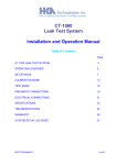
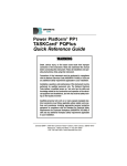
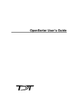
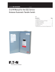
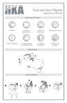
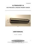
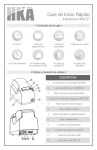
CT-1000
Leak Test System
Installation and Operation Manual
Table of Contents
Page
GENERAL OVERVIEW OF LEAK TESTING
2
CT-1000 LEAK TEST SYSTEM
6
OPERATION OVERVIEW
11
SETUP MODE
13
CALIBRATION MODE
18
TEST MODE
22
CHAINED (SEQUENCE) TESTING
26
RS232 DATA OUTPUT
27
PNEUMATIC CONNECTIONS
30
ELECTRICAL CONNECTIONS
32
SPECIFICATIONS
32
TROUBLESHOOTING
36
WARRANTY
37
CONVERSION CHARTS
38
SYSTEM SETUP LOG SHEET
39
HKA Technologies Inc.
June 2004
HKA CT-1000 Leak Tester Manual
Page 2
GENERAL OVERVIEW OF LEAK TESTING
Leak testing systems can be divided into three widely used basic methods.
The simplest method is water bath testing or bubble testing where the part to be tested
is filled with air at the required pressure and then immersed in water. An operator
visually inspects for bubbles appearing from any leak. This method is relatively
inexpensive and can detect small leaks (less than 1.0 sccm). The advantage is that one
can often pinpoint where the leak is on a given part. The disadvantage of this system is
its high human error factor due reliance on the operator to detect leaks; the inability of
the system to quantify the leak rate; and the need to dry most parts after testing. There
are some parts that cannot be allowed to get wet internally when leak tested.
The most expensive method, helium leak testing, is used to detect very small leaks
(less than 0.1 sccm). In these systems, the part is filled with helium gas and placed in a
container (often called a bell jar or clam shell) that traps any helium gas escaping
through the leak. A mass spectrometer is used to measure the relative amount of
helium in the container surrounding the part and a leak rate can be determined. These
types of systems are fast and accurate, but are also the most expensive with typical
systems costing over $100,000. Sniffer-type helium leak test systems (no container,
hand held helium sniffer) are also used but they may also suffer from the same kind of
human error factors as water testing.
The third method of leak testing uses air as a means of leak measurement. Either air
pressure or air flow are measured to detect leaks.
The simplest method of air leak testing is pressure decay testing where the test part is
pressurized to a given pressure and then isolated from the pressure source. A pressure
transducer is used to measure the pressure at the beginning of the test period and at
the end of the test period. The pressure drop over the time period is considered to be
due to the leak in the part. A leak rate can be calculated indirectly using this method.
An improvement o ver this method is called differential pressure testing. This method
uses a differential pressure transducer to measure the difference in pressure between a
known no leak part and the part under test after both have been pressurized and then
isolated from the pressure source. The leak rate can be calculated indirectly based on
the difference in pressure between the two parts over the test period.
Mass flow testing is a further improvement over the pressure decay systems above.
Differential mass flow also uses a no leak reference part but the differential pressure
transducer is replaced with a mass flow transducer. In this case the leak rate can be
measured directly without having to take time into consideration.
For many applications, the use of mass flow can allow for shorter test cycles than
differential pressure testing or pressure decay testing.
HKA Technologies Inc.
June 2004
HKA CT-1000 Leak Tester Manual
Page 3
Systems that use either differential pressure or mass flow to determine leak rates have
four distinct states in the test process:
First, the reference part and test part must both be pressurized to the required level.
This first state is often referred to as the "Fill" time.
In the second state, referred to as "Stabilization" time, both parts are isolated from the
pressure source, but air is allowed to freely flow from one part to the other. If insufficient
time is allowed for stabilization, accurate leak readings may not be possible.
In the third state, the free flow path between the reference part and the test part is
closed and the difference in pressure between the two parts or the flow of air between
the two parts is measured. This state is referred to as the "Measurement" or "Read"
time.
Finally, there must be the capability to exhaust the pressure from the part under test.
The reference part may also be exhausted at this time.
There are two transient conditions which effect leak rate measurement in systems using
air pressure.
The first condition is caused by adiabatic temperature changes as the air under
pressure expands (cools) to fill the test a nd reference parts, and then is compressed
inside the parts to the test pressure (heats up). Depending on part volume and test
pressure, it could take a significant time for the temperature effects to settle out. The
higher the pressure and/or the higher the volume the greater the impact of these
temperature changes. One advantage of using a no leak reference part is that it should
behave the same thermally as the part under test and the adiabatic temperature effects
should cancel out. While the temperature effects rarely fully cancel, test times are
greatly reduced.
The second transient effect is caused by the disturbance introduced when valves are
opened or closed. Apart from the sudden change in flow caused by operating a valve,
the opening or closing action tends to pump a small volume of air in one direction or the
other. Slowing down valve response helps, but some effects always remain. Depending
on the type of valve used, the valves may contribute to the temperature effects also.
One of the largest sources of error in air pressure leak test systems is due to external
factors that directly influence the temperature of the part under test. If the reference part
could be subjected to exactly the same external conditions, then this error would be
cancelled, but this is seldom practical in the shop environment.
Often parts to be tested come directly from a manufacturing process, and even simple
operations such as installing a screw can create enough heat from friction to heat up the
part enough to create errors in leak testing measurements. Since air follows the basic
gas laws, any change in the temperature of one of the parts will cause a change in
pressure directly proportional to the temperature change of that part. A small leak in a
HKA Technologies Inc.
June 2004
HKA CT-1000 Leak Tester Manual
Page 4
part can be "masked" by the increase in pressure from external temperature increases
to that part.
The first two transient effects can be overcome by having sufficient time in each test
state to allow the system to become stable.
The external effects of temperature on the test part may take many minutes or more to
become non-significant depending on part mass.
The total test time for any part depends on the following factors:
1 - Required leak test resolution and accuracy
2 - Volume of test part
3 - Test Pressure
4 - Thermal responsiveness of the part
5 - External temperature variations
Pneumatic connections from the part under test to the leak test system are usually
made with some form of flexible seal under some form of clamping pressure.
In setting up times for the leak test cycle, care has to be taken to ensure flexible seals
are still not "creeping" under pressure when the leak test measurement is made. The
"creep" in the seals can effectively reduce the volume of the part under test while
maintaining the same mass of gas thereby increasing the pressure in the test part.
Larger volumes in the test part reflect in longer test times, given other test conditions
are identical. It is therefore prudent to minimize the volume of the plumbing between the
test part and leak test system as this volume is in effect added to the test part volume.
All leak test systems require calibration for initial set-up.
A means for verifying calibration on a routine basis is also required.
The most common method of calibration employs a known "no leak" part, and a known
calibrated leak orifice. For the calibration process, a known no leak part is tested (with
also a no leak reference part) and the system should read "0" leak.
Then the known calibrated leak is added to the known no-leak test part and the system
should read the value of the calibrated leak.
Leak rates are usually given in sccm units which corresponds to a flow of standard
(normal atmospheric pressure) cubic centimeters of air (or other test gas) per minute.
HKA Technologies Inc.
June 2004
HKA CT-1000 Leak Tester Manual
Page 5
Other units of volume and time are also used and conversion rates are given at the end
of this manual.
HKA Technologies Inc.
June 2004
HKA CT-1000 Leak Tester Manual
Page 6
CT-1000 LEAK TEST SYSTEM
The standard configuration CT-1000 is a differential mass flow leak test system. It uses
a mass flow transducer to accurately measure flow from a reference part to the test
part.
Other configurations of the CT-1000 use simple mass flow for those low pressure, high
flow test situations such as mufflers, catalytic converters, air cleaners, manifolds etc.
The CT-1000 also incorporates a pressure transducer to enable accurate setting of the
test pressure and to monitor the pressure during the test cycle.
The system uses advanced microprocessor circuitry to deliver superior performance at
lowest cost.
2 LINE
LCD DISPLAY
POWER SWITCH
INCREMENT PUSH BUTTON
CT -1000 LEAK TEST SYSTEM
DECREMENT PUSH BUTTON
PROG/CAL/RUN PUSH BUTTON
ENTER PUSH BUTTON
TEST ON
PRESSURE
ADJUST
ACCEPT
REJECT
P
MADE IN CANADA
CT -1000 LEAK TEST-FRONT PANEL FUNCTIONS
A large backlit LCD readout displays all readings and set-up parameters.
Setup parameters for up to ten different parts are stored in a non-volatile EEPROM
which does not require battery backup.
All operations including set-up are made through a four button keypad located on the
front panel.
HKA Technologies Inc.
June 2004
HKA CT-1000 Leak Tester Manual
Page 7
All process valves are air operated eliminating any heating effect on leak measurement
caused by power dissipation in the solenoid coils.
Most internal pneumatic connections are made through a single internal manifold, thus
eliminating a large number of pneumatic lines and connections that could be subject to
potential leaks in the system.
USER
I/O
1
TEST
PORT
AIR
SUPPLY
REF
PORT
INT
REF
CAL
EXH
PORT
12
RS-232
POWER
24 V
AC/DC
CT -1000 LEAK TEST - REAR PANEL FUNCTIONS
All external pneumatic connections are made to the manifold located at the rear of the
leak test unit. These include ports for the reference part and the part under test, a port
for the calibrated leak, air supply in and exhaust ports.
All electrical connections are made through a removable twelve pin connector located
on the rear of the unit. The unit can be powered either by applying 24 volts through the
twelve connector or by the optional AC adapter.
There is also an RS-232 port on the rear panel allowing for connection to a PC for initial
set-up and for data logging.
Two software SETUPs are currently available.
HKA Technologies Inc.
June 2004
HKA CT-1000 Leak Tester Manual
Page 8
The first SETUP plots the graphs of the operation of the tester during the leak test cycle.
This is very useful for set-up and for ongoing monitoring of system performance.
The graphical representation of the leak test process is ideal in determining the
optimum test time for the part under the given test conditions.
The second SETUP produces production records on a daily (or other periodic) basis.
Figure 1 illustrates two typical leak test curves as taken from the RS232 port of the CT1000 test system.
The horizontal axis represents seconds of test time.
The vertical axis represents the leak rate in calibrated units of sccm.
The scaling for both axes is taken from the part set-up information sent to the PC
through the RS232 port on the leak test unit.
The lower curve is taken with a no leak part on the test port.
The upper curve has a 1 sccm calibrated leak added to the no leak test part.
In the set-up for the part being tested, the fill time is 5.0 seconds, the stabilization time
is 5.5 seconds and the read time is 10 seconds.
HKA PART TEST
06-24-1999 08:43:41
PRESS 55 PS I LEAK 1.0 SCCM
3.0
2.4
1.8
1.2
.6
4
HKA Technologies Inc.
8
12
16
20
24
June 2004
HKA CT-1000 Leak Tester Manual
Page 9
Figure 2 shows the valve states and air flow during the fill state.
AIR
SUPPLY
FILTER
PRESSURE
REGULATOR
50uM
FILL
PT
STAB-1
FILTER
OPEN
OPEN
REFERENCE PART
50uM
FILTER
5 uM
MF
FIG. 2
FILL STATE
CAL LK
CALIBRATED LEAK
STAB-2
FILTER
OPEN
50uM
CLSD
FILTER
5 uM
TEST PART
EXH.
CLSD
Figure 3 shows the valve states and air flow during the stabilization state.
AIR
SUPPLY
FILTER
PRESSURE
REGULATOR
50uM
FILL
CLSD
PT
STAB-1
OPEN
FILTER
REFERENCE PART
50uM
FILTER
5 uM
MF
FIG. 3
STABILIZATION
STATE
CAL LK
CALIBRATED LEAK
STAB-2
FILTER
OPEN
50uM
CLSD
FILTER
5 uM
TEST PART
EXH.
CLSD
Figure 4 shows the conditions for the read state. Note that the curve during the read
state exponentially approaches the final value of either "0" for the no leak case or "1.0"
for the 1 sccm leak case. As can be seen from the graph the difference between no leak
and a 1sccm leak is clearly evident after 3 seconds of the read state, but to get a true
sccm value for the final leak, a time of 10 seconds is required.
HKA Technologies Inc.
June 2004
HKA CT-1000 Leak Tester Manual
AIR
SUPPLY
FILTER
PRESSURE
REGULATOR
50uM
Page 10
FILL
CLSD
PT
STAB-1
CLSD
FILTER
REFERENCE PART
50uM
FILTER
5 uM
MF
FIG.4
READ STATE
CAL LK
CALIBRATED LEAK
STAB-2
FILTER
CLSD
50uM
CLSD
FILTER
5 uM
TEST PART
EXH.
CLSD
HKA Technologies Inc.
June 2004
HKA CT-1000 Leak Tester Manual
Page 11
OPERATION OVERVIEW
The CT-1000 system can be SETUPmed to test up to ten different parts as long as the
test pressures are all within the range of the leak test unit.
The calibrated leak used with the system must be in the correct order of magnitude for
the parts family.
2 LINE
LCD DISPLAY
POWER SWITCH
INCREMENT PUSH BUTTON
CT -1000 LEAK TEST SYSTEM
DECREMENT PUSH BUTTON
PROG/CAL/RUN PUSH BUTTON
ENTER PUSH BUTTON
TEST ON
PRESSURE
ADJUST
ACCEPT
REJECT
P
MADE IN CANADA
CT -1000 LEAK TEST-FRONT PANEL FUNCTIONS
The selected part number is displayed at the left of the top line of the LCD display.
The test unit can be in one of three conditions as set by the "Mode" button (the button to
the right of the down arrow) - SETUP Mode, TEST Mode, or Calibrate Mode.
When power is removed and reapplied to the unit it will always start in the same mode
as it was in when power was turned off.
Repeatedly pushing the mode button will scroll from TEST, to SETUP, to Calibrate, and
back to TEST. The selected Mode is indicated on the top line of the LCD display.
In TEST or Calibrate Mode the left top of the LCD display is used to indicate any fault
conditions or if there are no faults present "RDY" will be displayed indicating system is
ready.
The bottom line of the LCD is used to display variable parameters for the test system.
The left half of the display identifies the parameter while the right ha lf of the display
identifies the numeric value of that parameter.
HKA Technologies Inc.
June 2004
HKA CT-1000 Leak Tester Manual
Page 12
Pushing the enter button (right hand button) will scroll thru the various parameters
available in the Mode selected.
In SETUP Mode only, the Up and Down arrow buttons can be used to change the
numeric value of the parameter being displayed.
In order to change any value, the correct PassWord must have been entered. Without
the correct PassWord, the various parameters can only be examined, not changed.
In TEST Mode, the Up and Down arrow keys are only used to toggle between "YES"
and "NO" for the parameter "Clear Counters".
The Up and Down arrow keys have no function in Calibrate Mode.
The illustration shows the location of the four push buttons and LCD display used to
SETUP and control the leak test unit.
PART NUMBER
MODE
VALUE
PARAMETER
P
HKA Technologies Inc.
June 2004
HKA CT-1000 Leak Tester Manual
Page 13
SETUP MODE
SETUP Mode is used to select the desired part number (1 thru 10) and to input or
change any of the parameters associated with that part number.
The new or revised parameters are saved in EEPROM any time the Mode is changed
from SETUP to TEST or TEST to Calibrate.
To access the SETUP function push the MODE key until "SETUP" is displayed on the
top line of the LCD display.
In order to select a different part number or change any parameter value, push the
ENTER (far right button) until the parameter PassWord appears.
Use the Up and Down arrow keys to enter the two digit factory set default "22". If your
test system has a different PassWord it will be shown in the "specifications" section of
this manual.
When the display reads the correct PassWord push the ENTER.
PART NUMBER
MODE
VALUE
PARAMETER
P
The bottom line of the LCD display should now read "Part No" followed by a number
from 1 to 10. Note the same number is shown at the top left of the LCD display "PN"
(followed by number 1 to 10). If the number displayed is the desired part number to
HKA Technologies Inc.
June 2004
HKA CT-1000 Leak Tester Manual
Page 14
input new or revised parameters, push the ENTER key again. If the part number is to be
changed use the Up and Down arrow keys to select the correct part number.
Note that the value displayed for part number will not exceed 10. When the correct part
number is displayed, push the ENTER button. The top left of the LCD will show the new
part number.
The bottom line of the LCD will now show “Tim Base” followed by either 1.0 SEC or 0.1
SEC. Use the Up or Down arrow keys to select the desired time base for system
parameters. Note with a 1.0 SEC time base, each time parameter can be varied from 5
seconds to 999 seconds, while the 0.1 SEC time base allows time parameters to be
varied from 0.5 seconds to 99.9 seconds.
The bottom line of the LCD will now show "FillTime" followed by a numeric value. Use
the Up or Down keys to select the desired time for this state. Note the range of values
for FillTime is 0.1 to 25.5 seconds changeable in 0.1 second increments. When the
correct value is displayed push the ENTER key again.
The bottom line of the LCD will now show "StabTime" followed by a numeric value.
This is the time for the stabilization state and it also can be varied from 0.1 to 25.5
seconds in 0.1 second increments. When correct value is displayed push the ENTER
key again.
The bottom line of the LCD will now show "ReadTime" followed by a numeric value.
This is the time for the leak reading to reach its final value, or to reach an acceptable
value approaching the final leak value. As for the previous parameters, the range is 0.1
to 25.5 seconds with 0.1 second increments. With the correct value displayed, push the
ENTER key again.
The bottom line of the LCD will now show "Leak Lim" followed by a numeric value. This
value corresponds to the lowest leak reading that will be termed a failure by the leak
test system. With the leak readout rounded off to 0.1 sccm, a value of 0.05 sccm lower
than the leak limit would be shown as a failure.
For example if the leak limit was set to 2.0 sccm, a leak reading of 1.95 sccm would be
termed as a failure. The leak limit can be varied from 0.1 to 25.5 sccm in 0.1 sccm
increments using the Up and Down arrow keys. When the correct leak limit is displayed,
push the ENTER key again.
The display will now show "Cal Leak" followed by a numeric value on the bottom line.
This number must correspond to the leak value in sccm of the calibrated leak attached
to the test unit.
Note that since the leak rate of the calibrated leak will vary with pressure, the value
displayed for the parameter "Cal Leak" must be the leak value at the set test pressure.
The range of allowable calibrated leak values varies from 0.5 to 25.5 sccm. More
information on the calibrated leaks is detailed in the section "Calibration Mode”. When
the correct value for the calibrated leak is displayed, push the ENTER key again.
HKA Technologies Inc.
June 2004
HKA CT-1000 Leak Tester Manual
Page 15
The next selection to be made is the choice of “zero” to be used during the test cycle.
The displayed parameter is “FlowZero” and the two options are “Cal” or “Stab”. With
the “Cal” option selected, the zero reference used for each test will be the “0” value
obtained during the first two passes of the calibration cycle. With the “Stab” option
selected, the zero reference used for each test will be the flow transducer reading at the
end of the stabilization time. It is generally preferable to use the “Stab” option as a new
zero is obtained during each test cycle, which compensates for changes in ambient
temperature and long term drift of electronic components. The “Cal” option is used when
short cycle times do not allow sufficient time to obtain a stable flow reading and this
option is also used for all applications of simple mass flow (as compared to the standard
differential mass flow).
The next parameter to be displayed is “MaxSlope”. With mass flow technology, the
leak reading does not vary with time, after transient conditions are allowed to settle out.
The value displayed can va ry from 0.1 to 10.0 CCM. The value corresponds to the
allowable change in leak during the last one third of the READ cycle. The value is
calibrated in SCCM per minute. A low value such as 0.1 CCM will give a test error as
indicated by an *U or *D (at the top right of the LCD display) if there is a very small
slope in the leak reading during the last one third of read time. Conversely a high value
such as 10.0 will allow a very large change in the Leak value during the last one third of
the read time without indicating any error condition. The *U indicates an upward slope to
the leak readings while an *D indicates a downward slope to the leak readings. If either
an *U or *D appears, the pass output is not turned on at the end of the Read time.
Depending on customer requirements at the time of order, the fail output may or may
not be energized in the event of a slope error as indicated by *U or *D.
The next displayed parameter is “Min Flow”. This value can be changed from 0.1 CCM
to to 5.0 CCM. The value entered is the allowable leak below “0”. Leak rates below “0”
can occur with cold parts being tested relative to the reference part. This parameter puts
a limit on how much “negative” flow will be accepted and a pass output given at the end
of the read cycle. If the value is outside limits an *- will appear at the top right LCD
display. As was the case for slope errors, a pass output is not given at the end of read if
this limit was exceeded and a fail output may or may not be energized depending on
specifications made at time of purchase.
The next parameter to be displayed is "Pres Tol" followed by a numeric value. This is
the tolerance for the test pressure at which the system will indicate a fault (and abort the
test sequence). The value is in percent of the set test pressure and can be varied from 0
to 20 in increments of 1.
With mass flow leak sensing, a given leak reading will change directly as the test
pressure - a 1% psi change in pressure will result in a 1% change in a given leak rate.
The precision regulator used in the test system should be able to maintain test
pressures within +/- 2% and therefore any value of 2 or more for pressure tolerance
would be acceptable. Again use the Up and Down arrow keys to select the desired
value and then push the ENTER key.
HKA Technologies Inc.
June 2004
HKA CT-1000 Leak Tester Manual
PART NUMBER
Page 16
MODE
VALUE
PARAMETER
P
The setup parameters for any part are saved only under the following conditions:
1 - Part number changed in SETUP mode
2 - After completion of test cycle in TEST mode
3 - After completion of a successful CAL cycle
The display will now show "Pressure" followed by a numeric value. When this
parameter is accessed the valves will change state to allow the pressure transducer to
read the test pressure.
The system must be connected to an air supply to enable the pressure parameter
to be set.
To set pressure adjust the regulator knob on the front of the test until the correct reading
is displayed.
Note the regulator has a one to two second response time after adjustment and
that time should be allowed for a final pressure to be reached.
Once the pressure has stabilized at the correct value, push the ENTER key again.
Note: The pressure readout is in psig units and has a resolution of one psig.
HKA Technologies Inc.
June 2004
HKA CT-1000 Leak Tester Manual
Page 17
The last option (software version 4.20 or later) is “Fast Cycle” followed by either “Yes”
or “No”. With the fast cycle enabled (Yes), the system will give a pass output during the
read cycle as soon as the leak value is lower than the leak limit and the slope of leak vs
time is zero or negative. This allows a much shorter test cycle in many applications. It is
important to note that the short cycle ensures the part being tested is within the leak
limit parameter, but the final value of the leak for the part being tested remains
unknown.
The SETUPming is now complete for the selected part number and the bottom line of
the display will again read PassWord followed by the correct number.
The following lists all the parameters accessible in SETUP mode and also indicates the
range of values and units for each parameter:
1. PassWord
0 - 99 ( 22 factory default)
2. Part Number
1 – 10
3. Tim Base
0.1 or 1.0 SEC
4. FillTime
0.5 - 25.5 seconds or 5 – 255 seconds
0.5 – 99.9 seconds or 5 – 999 seconds
5. StabTime
0.5 - 25.5 seconds or 5 – 255 seconds
0.5 – 99.9 seconds or 5 – 999 seconds
#
#
6. ReadTime
0.5 - 25.5 seconds or 5 – 255 seconds
0.5 – 99.9 seconds or 5 – 999 seconds
#
7. Leak Lim
0.1 - 25.5 sccm
8. Cal Leak
0.5 - 25.5 sccm
9. FlowZero
Stab or Cal
10. MaxSlope
0.1 – 10.0 sccm
11. Min Flow
0.1 – 5.0 sccm
12. Pressure To l
0 – 20 %
13. Pressure (Standard Model)
0 - 125* psig
14. Fast Cyc
Yes or No #
# Version 4.20 firmware or later only.
* subject to available air supply pressure
HKA Technologies Inc.
June 2004
HKA CT-1000 Leak Tester Manual
Page 18
CALIBRATION MODE
After all the parameters have been SETUPmed for a particular part, the system has to
be calibrated to read the correct leak.
It is accessed by pushing the Mode key until CAL appears.
PART NUMBER
MODE
VALUE
PARAMETER
P
To perform the calibration process in a differential mass flow system like the CT-1000,
two known no leak parts are required, one for the reference port and one for the test
port.
The calibrated leak must be attached to the leak test unit and the correct leak rate in
sccm must have been entered into the SETUP for the part to be tested.
In the calibration process the test system first goes through two complete test
sequences with the valve closed to the calibrated leak.
This gives two "numbers" that correspond to a zero leak reading.
If these two numbers are the same or within a given tolerance of each other, the two
numbers are averaged to obtain a zero leak reference.
After the zero leak reference is obtained, the system again goes through two complete
test sequences but this time with the valve open to the calibrated leak.
HKA Technologies Inc.
June 2004
HKA CT-1000 Leak Tester Manual
Page 19
The system now has two new readings which correspond to the known leak rate.
Again the two numbers are compared to each other and if within a given tolerance, they
are averaged together and used as the factor to calculate the leak rate.
It is important to note that the calibration test sequence is identical to the TEST test
sequence in terms of test pressure and times for the various states in the test
sequence.
If any of the parameters except Leak Limit or Pressure Tolerance are changed in
SETUP mode the system has to be recalibrated.
If the parts to be tested are different from those used during calibration the system has
to be recalibrated, even though no parameters are changed in the SETUP menu.
To enter the calibration function push the MODE key until CAL RDY appears on the top
right of the LCD display.
Make sure proper air pressure is applied, known no leak parts are attached to the
reference and test ports, and that the correct calibrated leak is in place.
Also ensure a jumper is connected between terminals 2 and 3 of the user I/O connector
or a switch between these terminals is in the closed position.
There are a number of parameters that may be displayed on the bottom line of the LCD
when in CAL mode. (The parameter displayed is the same as the last time the CAL
mode was accessed.)
It does not matter which parameter is displayed to start the CAL procedure.
The calibration procedure automatically TESTs through four complete test cycles, two
with no leak added and two with the calibrated leak applied. When completed the
system will have established offset and gain constants named "F Zero" and "F Fact".
Push the start test button (Close contacts between terminals 2 and 11 of the user I/O
connector.)
The bottom line of the LCD display will now read "Zero 1" followed by a numeric value.
This value will change to "0" as soon as the test sequence begins. The system will now
go through a complete test cycle and when complete will display a new value in place of
the "0" reading.
The system will also go through a drain cycle, discharging the air from both the
reference part and the part under test.
After a short delay to ensure all of the pressurized air is allowed to escape from both
parts, the test sequence is automatically repeated. There is no need to push the start
test button again.
HKA Technologies Inc.
June 2004
HKA CT-1000 Leak Tester Manual
Page 20
When the test sequence starts this second time, the bottom LCD will show the
parameter "Zero 2" followed by a numeric value. This value will change to "0" as soon
as the test sequence begins.
At the end of the test cycle the "0" will be replaced by a new value.
The two values Zero 1 and Zero 2 are compared and if close enough in value to each
other are averaged together to establish a zero leak offset called "F Zero".
Again after a short delay for venting, the test cycle will repeat automatically.
This time the calibrated leak valve will be open and the bottom line of the LCD will read
"Cal 1" followed by a numeric value. This number will change to "0" as soon as the test
starts and will be replaced by a new value at the end of the test.
The process will be repeated for a second test where a new value for "Cal 2" will be
established.
The values of "Cal 1" and "Cal 2" are compared and if their difference is in limits, the
values are averaged and divided by the known calibrated leak to obtain a constant that
is used to calculate the leak rate in sccm called "F Fact".
The following summarizes the parameters that can be displayed when the system is in
Calibration mode.
To view each parameter, press the ENTER (right) key.
PART NUMBER
MODE
VALUE
PARAMETER
P
HKA Technologies Inc.
June 2004
HKA CT-1000 Leak Tester Manual
Page 21
Note that none of the parameters can be changed by the Up and Down arrow keys - all
parameter values are automatically generated by the system in the calibration
procedure.
All of these values are dimensionless.
1. Zero 1
-first no leak value read
2. Zero 2
-second no leak value read
3. Cal 1
-first reading with calibrated leak
4. Cal 2
-second reading with calibrated leak
5. F Zero
-offset (average of Zero 1, Zero 2)
6. F Fact
-gain value (calculated from average of Cal 1 and
Cal 2
and the value of the calibrated leak)
If the times for the various states (Fill Time, Stabilization Time, Read Time) are not long
enough for the test conditions, the values of Zero 1 and Zero 2 or Cal 1 and Cal 2 may
not be close e nough for the system to get valid numbers for F Zero and F Fact.
If this is the case, an asterisk (*) followed by a letter (A,P,S,Z) will appear at the top right
of the LCD display.
If this occurs, the calibration procedure will be aborted and no new values of F Zero and
F Fact will be calculated.
For more information on calibration fault conditions, please refer to the section entitled
"Troubleshooting".
HKA Technologies Inc.
June 2004
HKA CT-1000 Leak Tester Manual
Page 22
TEST MODE
TEST Mode is the normal test state of the leak test system.
It is accessed by pushing the Mode key until TEST appears.
PART NUMBER
MODE
STATUS
VALUE
PARAMETER
P
When in TEST Mode, the top left of the LCD displays the part number while the top right
displays " TEST" followed by "RDY".
The bottom line of the LCD can display a number of different parameters which are
scrolled through by pushing the ENTER key.
The following summarizes the parameters that can be displayed along with the
corresponding range of values and units when in TEST Mode.
1. Leak
0.0 - 25.5
sccm
2. Pres
0.0 - 125
psig
3. Flow
0.0 - 25.5
sccm
4. Pass Cnt
0 - 65,535
5. Fail Cnt
0 - 65,535
6. TotalCnt
0 - 65,535
7. Clr Cnts
"No" / "Yes" (toggle with Up / Down keys)
Leak is the measured leak rate in sccm units of the last part tested.
HKA Technologies Inc.
June 2004
HKA CT-1000 Leak Tester Manual
Page 23
Pres is the test pressure during both the Fill and Stabilize states. Pressure is not read
during the Read state.
Flow corresponds to the current reading of the mass flow transducer at any point in
time during the test. At the end of each test, Flow and Leak have the same value.
The last four parameters refer to the counters in the system used to track the total
number of tests, the number of passed tests and the number of failed tests.
The "Clr Cnts" is an abbreviation for Clear Counters and the default when this
parameter is viewed is "No".
To clear the counters use either the Up arrow key or the Down arrow key to change the
display to "Yes" and then push the ENTER key.
When in TEST Mode the bottom line of the LCD can be left displaying any of the
parameters listed for TEST mode, but the most common parameter to be displayed
would be "Leak" indicating the measured leak rate in sccm of the last part tested.
PART NUMBER
MODE
STATUS
VALUE
PARAMETER
P
The test is started in TEST mode by momentarily connecting terminals #2 and #11 on
the I/O connector. Once the test is in progress, it will complete the entire sequence
unless the Abort input is made by momentarily connecting terminals #2 and #9 on the
I/O connector.
The top line of the LCD display will show the part number on the left side of the display
"PN xx" followed by "TEST" followed by "RDY" on the left side.
HKA Technologies Inc.
June 2004
HKA CT-1000 Leak Tester Manual
Page 24
When the test has been started, the "RDY" will change to "FILL" indicating the
sequence is at the Fill state.
When the Fill state is finished, the "FILL" will change to "STAB" indicating the
Stabilization state.
At the end of the stabilization state, the display will read "READ" until the test cycle is
finished. When the Read cycle is complete, the top right display will again show "RDY"
indicating the system is ready for the next test cycle.
The test system will also automatically exhaust pressure from both the reference part
and test part at the end of the Read state.
During the test sequence, the test pressure is monitored during the Fill state and the
Stabilization state.
If the test pressure is outside limits as specified by the Pressure and Press Tolerance
parameters, the test sequence will be aborted and the top right of the LCD will display
"RDY*P" indicating a pressure fault has occurred.
The CT-1000 has three isolated output contacts for user interfacing. These are test in
progress, passed test, and failed test.
The test in progress contacts are closed during the Fill, Stabilization, and Read states of
the test sequence.
Either the test passed or test failed contacts will be closed at the end of the read cycle
depending on the results of the leak test.
These contacts will be maintained until the start of the next test cycle or until power is
turned off in the test unit.
HKA Technologies Inc.
June 2004
HKA CT-1000 Leak Tester Manual
Page 25
CHAINED (SEQUENCE) TESTING
For certain applications, the leak test system is required to perform sequential testing on
two different parts, for example a valve in open positions could be Part #1 and the valve
in a closed position could be Part #2.
To be able to test a different part without going thru the SETUP mode, there is an
auxiliary input (terminal #10) on the I/O connector which when energized will select the
next test SETUP to be TEST.
The following outlines considerations when using this “chained” test sequence.
1. The two part numbers must be consecutive. The first part number can be in
the range of 1 to 9. Part 10 is not valid for the first part number of a chained
test and errors will occur if this part is selected. The second part will be the
next higher part number from the first part.
2. The second part is selected in TEST mode by turning on the auxiliary input on
the I/O connector.
3. The auxiliary input only works in TEST mode. Do not turn on the Auxiliary
input until both parts have been SETUPmed and calibrated. Ensure the first
part is selected when the system is put into TEST mode and that the auxiliary
input is off. Failure to follow this procedure may result in setup parameters
being mixed between the two parts selected for chained operation.
4. After SETUPming the setup parameters for the second part, change the part
number to any other part to save the setup information. This is good practice
for any part being SETUPmed.
5. Calibrate both parts as would be done if the parts were not to be tested in a
chained sequence.
6. When the auxiliary input is on in TEST mode, the display will show the new
part number.
7. The parameter being displayed in TEST mode will be the same for both parts
in the chained sequence. For example if the parameter LEAK is displayed for
the first part, it will also be displayed for the second part. The parameter to be
displayed can be changed when in TEST mode when either part is being
tested.
8. The GOOD, BAD, TOTAL part counters work as if the two parts being tested
were separate. Each will only get updated when its part number is selected in
TEST mode.
HKA Technologies Inc.
June 2004
HKA CT-1000 Leak Tester Manual
Page 26
RS232 DATA OUTPUT (Ver. 3.90 or lower)
When in TEST mode, the test system continuously outputs a data string to the RS232
port.
The information sent via the RS232 port consists of the following ASCII data:
HXMTCPPPPFFFFSSSSQQQE
where:
H = SOH
X = STX
M = Mode
P = SETUP
R = TEST
C = Calibrate
T = Test Status
F = Fill
S = Stabilization
R = Read
Y = Ready
C = Completion Status
N = Normal
A = Aborted
P = Pressure fault
Z = Zero cal error
S = Span cal error
P = Pressure value (4 digits)
F = Flow rate (4 digits)
S = Flow scale factor
Q = Sum of Fill, Stab. Read times
E = EOT
HKA Technologies Inc.
June 2004
HKA CT-1000 Leak Tester Manual
Page 27
RS232 DATA OUTPUT (Ver. 4.20 or higher)
ABCCCDDEFGHHHIIIJJJJKKKKLLLLMNNNOOOPPPQQQRRSSSTTTUUUUVVVVW
XXXXYYYZZA
where:
A = SOH
B = STX
C = Version Major / Minor / Maintenance
D = Part Number (1 – 10)
E = Mode
P = SETUP
R = TEST
C = Calibrate
F = Test Status
F = Fill
S = Stabilization
R = Read
Y = Ready
G = Completion Status
N = Normal
A = Aborted
P = Pressure fault
Z = Zero cal error
S = Span cal error
D = Neg slope error during Read
U = Pos slope error during Read
- = Negative flow error during Read
X = Reserved for future use
Y = Reserved for future use
O – Reserved for future use
H = Current Pressure Value (0 - 500)
I = Pressure Reference Value (0 – 500)
J = Scaled Flow rate (0 - 4095) ** in 0.1 LPM units
K = Flow scale factor (0 – 4095)
M = Time base:
1 = 1.0 Second; 2 = 0.1 Second
N = Reserved for future use
O = FILL time (0 – 255), (0 – 999 for ver. 4.20 or later)
P = STAB time (0 – 255), (0 – 999 for ver. 4.20 or later)
Q = READ time (0 – 255), (0 – 999 for ver. 4.20 or later)
R = Reserved for future use
S = Reserved for future use
T = Reserved for future use
U = Leak limit (0.0 – 25.5)
V = Calibrated Leak (0 – 25.5)
W = Zero Selection:
1 = Cal; 2 = Stab
X = Leak slope limit (0.1 – 10.0)
Y = Leak negative limit (0.1 – 5.0)
Z = Pressure Tolerance (0 – 20)
A = EOT
HKA Technologies Inc.
June 2004
HKA CT-1000 Leak Tester Manual
Page 28
The data from the RS232 port can be input to any IBM compatible computer system
(PC).
There are currently two versions of software offered by HKA, the first will graph the
reading of the mass flow transducer.
The second SETUP will summarize leak test results using SPC type format.
The user can also input the data from this port into their own custom SETUP using the
format as outlined.
All data transfer is unidirectional, from the CT-1000 test system to the PC monitoring
system.
There is no effect on the leak test system if the PC is connected to the RS232 port or
not.
The serial data has the following format:
Speed:
9600 baud
Parity:
none
Data:
8 bits
Stop Bits:
1
RS:
request to send suppressed
CS:
CS(0)
DS:
DS(0)
CD:
CD(0)
The RS232 uses a standard 9 pin sub-miniature female "D" connecto r with the following
pin assignments:
Pin 1
nc
Pin 2
data out
Pin 3
data in
Pin 4
joined to 6
Pin 5
common
Pin 6
joined to 4
Pin 7
joined to 8
Pin 8
joined to 7
HKA Technologies Inc.
June 2004
HKA CT-1000 Leak Tester Manual
Pin 9
HKA Technologies Inc.
Page 29
nc
June 2004
HKA CT-1000 Leak Tester Manual
Page 30
PNEUMATIC CONNECTIONS
All pneumatic connections are made through a manifold located at the back of the test
system.
USER
I/O
1
TEST
PORT
AIR
SUPPLY
REF
PORT
INT
REF
CAL
EXH
PORT
12
RS-232
POWER
24 V
AC/DC
CT -1000 LEAK TEST - REAR PANEL FUNCTIO N S
All connections have 1/8 NPT female threads.
From left to right facing the rear of the test unit, the ports have the following functions.
TEST PORT:
This port is connected to the part being leak tested. The fittings used
should provide a reliable, leak free seal from the port to the part under
test. The tubing should be kept as short as possible to reduce effective
added volume of the test part.
AIR SUPPLY:
The user must provide clean, dry air to the leak test system. Air should
be filtered with a 50 micron maximum element, and depending on the
level of moisture present in the air, may require the use of a desiccant
type dryer. While any significant leaks on this port would waste air, there
would be no effect on the accuracy of the leak test measurement.
HKA Technologies Inc.
June 2004
HKA CT-1000 Leak Tester Manual
Page 31
REF PORT:
This port should be connected to a known no leak part identical to the
part under test. Other reference volumes may be used which are similar
in size to the parts being tested, but they may add to the test times to
obtain the same accuracy as an identical part. All connections must be
leak free and again, care should be taken to minimize any added volume
from tubing length.
INT REF:
As an option the CT-1000 leak test system may have a fixed volume
reference built into the unit. While not as optimum as an identical
reference part, the fixed volume may be used where the same level of
accuracy in the same test time is not required, or where there are several
different parts of similar volumes to be tested, and changing reference
parts for each different part may not be warranted. If an internal
reference is used, the test system will be shipped with connectors and
tubing joining the INT REF port to the REF PORT.
In many CT-1000 leak test units this port is marked “AUX. PORT”.
Please consult the documentation shipped with the particular CT-1000
unit to determine the function (if any) of this pneumatic connection.
CAL:
In order to set-up the system to test any part, an appropriate calibrated
leak must be connected to this port again using quality no leak fittings. If
ordered with the leak test unit, the calibrated leak will be factory installed.
Once set up the calibrated leak is not required to TEST the test system,
but it is required to perform periodic tests on the performance of the leak
test system. It is recommended that a system performance check be
done at the start of each shift of operation. The calibrated leak can be
enabled by removing the jumper between terminals #2 and #3 on the
user connector. More information on this function will be detailed in the
section entitled "Electrical Connections".
EXH PORT:
This port is used to exhaust the air from the reference part, the test part,
and the internal valves in the test system. Normally this port is left open,
but in very clean or quiet environments the user may wish to connect
tubing to this port and lead the exhaust air to a different area.
HKA Technologies Inc.
June 2004
HKA CT-1000 Leak Tester Manual
Page 32
ELECTRICAL CONNECTIONS
The user connector has screw terminals and is removable for easy wiring.
The terminal designations are from 1 to 12 starting at the top of the connector.
This connector is polarized and cannot be inserted in any but the correct position.
All interfacing to the test unit is done through this connector.
The CT-1000 leak test system may be powered through the 12 pin user connector with
24 volts DC, or using the AC adapter plug which delivers 24 volts. The current draw for
both is 500 mA.
If powered with 24 DC, the positive power input is terminal #2 and the power common () is terminal #1.
There are three inputs to the test system; start test, abort test, output mode select.
TYPICAL
USER
CONNECTIONS
USER I/O
CONNECTOR
+
24V
CAL LEAK SOL
NC
TYPICAL
INPUT
CIRCUIT
2K2
2K2
2K2
1
POWER COMMON
2
24 VDC USER / INPUT
3
CAL LEAK ENABLE
4
RELAY COMMON
5
6 TEST ON
7 PASSED TEST
8 FAILED TEST
9
ABORT TEST
10
OUTPUT MODE
11
START TEST
12
INPUT COMMON
1
2
3
4
5
6
7
8
9
10
11
12
CAL LEAK
CLOSE=NORMAL OPERATION
RELAY COMMON
USER CONTROL
TEST ON
PASSED TEST
FAILED TEST
ABORT TEST
CHAINED TEST SWITCH
CLOSE FOR HIGHER PART SELECT
START TEST
These inputs can be powered from an external 24 DC source, or used with isolated
contacts along with the 24 volts available on the user connector.
To use an external 24 volts for these inputs, connect terminal #12 to the output common
of the user system and connect the positive signal outputs to terminals #9, #10, #11.
The inputs draw 10 mA current each.
When driven from isolated contacts, join terminals #1 and #12 of the user connector.
HKA Technologies Inc.
June 2004
HKA CT-1000 Leak Tester Manual
Page 33
The relay contacts are connected to terminals #2 and #11 for start test; #2 and #9 for
abort test; and terminals #2 and #10 to set the output mode.
With no input on terminal #10, the passed test or failed test output will be on (relay
contacts closed) from the end of the test to the start of the next test.
With terminal #10 energized (or joined to #2) the relay contacts for the passed test or
failed test outputs will be on for 100 milliseconds after the completion of the test cycle.
There are three user outputs available on the 12 pin connector.
Terminal #4 is the common for all outputs that have isolated relay contacts rated at 5
amperes, 250 volts.
Terminal #6 relay contacts are closed for the duration of the test sequence - Test On
output.
Terminal #7 is connected to the passed test relay contacts while terminal #8 is
connected to the failed test relay contacts.
Terminal #3 is connected to the calibrated leak enable solenoid valve. For normal
operation in TEST mode and Calibration mode, this terminal is joined to terminal #2.
To enable the calibrated leak, disconnect the terminal #3 from terminal #2. If desired a
switch may be used between terminals #2 and #3. With the switch closed, normal
operation takes place. With the switch open, the calibrated leak is applied to the test
part. This provides an easy method of verifying system performance by reading the
value of the calibrated leak in TEST mode.
Note that a known no leak test part must be used to read the correct leak rate of
the calibrated leak.
HKA Technologies Inc.
June 2004
HKA CT-1000 Leak Tester Manual
Page 34
SPECIFICATIONS
(STANDARD UNIT)
Measurement system:
Mass Flow Transducer
Number of SETUPs:
10
SETUP Storage:
Non Volatile EEPROM
Display:
2 Line x 16 Characters
High Contrast Backlit LCD
Pressure Range:
Standard 0 - 125 psig (9.0 bar/g)
Other ranges available
Leak Range:
0 - 25.5 sccm
Using 0.1 sccm resolution
Test Parameters:
#1)
Fill Time
0.5 .... 25.5 sec. (0.5 – 999 sec)
Stabilize Time 0.5 .... 25.5 sec. (0.5 – 999 sec)
#1)
Read Time
0.5 .... 25.5 sec. (0.5 – 999 sec)
#1)
#1 version 4.20 or higher
Internal Counters:
Total cycles
Passed Test
Failed Test
User Inputs:
Start Test
Abort Test
TEST Next Part (Chained)
User Outputs:
Test in Progress
Passed Test
Failed Test
User Connections:
12 pin removable connector
(supplied with unit)
Communications:
RS232 Serial Port
(9 pin subminiature "D" conn.)
Air Requirements:
60 - 150 psig ( 4 - 10 bar/g)
Clean, Dry Air.
Air Connections:
1/8 NPT Female Ports
HKA Technologies Inc.
0 .... 65,536
0 .... 65,536
0 .... 65,536
June 2004
HKA CT-1000 Leak Tester Manual
Page 35
Power Requirements:
24 VDC at 300 mA
24 VAC at 300 mA
(optional adapter)
Dimensions:
12" wide, 6" high, 8" deep.
(533 mm wide, 152 mm high, 203 mm deep)
Weight:
Approx. 6.4 lbs ( 2.9 kg )
PassWord:
22 factory Default …… or ________
Calibrated Leak:
Required for set-up
Specify leak rate and pressure
(option with test unit)
HKA Technologies Inc.
June 2004
HKA CT-1000 Leak Tester Manual
Page 36
TROUBLESHOOTING
1. LCD DISPLAY BLANK:
• Make sure power rocker switch in on position
• Verify 24 volt supply to unit
• Make sure no shorts in field wiring to user I/O connector
2. SYSTEM WILL NOT START IN TEST MODE:
• Check connections to user I/O connector
3. SYSTEM STOPS PART WAY THRU IN TEST MODE:
• *P displayed at top right of LCD
• Verify air pressure to test system
• Gross leak in part under test
• Pressure dropped below limits during test
4. SYSTEM STOPS PART WAY THRU IN TEST MODE:
• *A displayed at top right of LCD
• Abort input turned on during test
5. SYSTEM DISPLAYS ERROR CODE *U AT END OF READ CYCLE
• Upward (positive) slope above limit at end of read cycle
6. SYSTEM DISPLAYS ERROR CODE *D AT END OF READ CYCLE
• Downward (negative) slope above limit at end of read cycle
7. SYSTEM DISPLAYS ERROR CODE *- AT END OF READ CYCLE
• Leak below zero at end of read cycle
8. SYSTEM WILL NOT ACCEPT CHANGES IN SETUP MODE:
• Verify correct Password entered
9. SYSTEM STOPS PART WAY THRU IN CALIBRATION MODE:
• *Z displayed at top right of LCD
• Two zero readings not within correct range or differ from
each other by more than allowable amount.
• Leak in reference port or test port plumbing
• Part temperature changing during test cycle
• SETUPmed times too short for stable readings
10. SYSTEM STOPS PART WAY THRU IN CALIBRATION MODE:
• *S displayed at top right of LCD
• Two span readings not within correct range or differ from
each other by more than the allowable amount.
• SETUPmed times too short for stable readings
HKA Technologies Inc.
June 2004
HKA CT-1000 Leak Tester Manual
Page 37
WARRANTY
The CT-1000 leak test system is guaranteed to be free from defects in materials and
workmanship for a period of one year from date of purchase.
The warranty does not cover units that have been modified, abused, or improperly
maintained or operated.
During the warranty period HKA will repair or replace at its option any unit that has been
found to be defective.
Any product to be returned under this warranty, must have an authorization number
from HKA and must be shipped prepaid to HKA in Burlington, Ontario or the nearest
authorized representative.
HKA’s liability for the leak test system is limited solely to the replacement or repair of the
product, and HKA will not be liable for any consequential damages.
HKA reserves the right to make on-going changes and upgrades the CT-1000 leak test
unit, and has no obligation to make modifications to products previously sold.
Any units returned to HKA after the warranty has expired will be subject to charges for
labour and materials and any shipping costs incurred.
For warranty, contact:
HKA Technologies Inc.
3536 Mainway
Burlington, Ontario
L7M 1A8
(905)336-8668 or FAX (905)336-8805
HKA Technologies Inc.
June 2004
HKA CT-1000 Leak Tester Manual
Page 38
CONVERSION CHARTS FOR COMMON LEAK RATE UNITS
The CT-1000 leak test unit uses sccm (standard cubic centimeters per minute) units for
display and limits.
The following chart gives conversion factors for other commonly used units for leak rate
measurement.
To convert to sccm from the following units multiply by the given factors:
c.c./sec
-
60
c.c./hour
-
0.0167
litres/min
-
1000
cu.in/min
-
16.39
cu.ft/hour
-
472
oz./yr
-
0.011 (air at standard atmospheric conditions)
HKA Technologies Inc.
June 2004
HKA CT-1000 Leak Tester Manual
Page 39
CT-1000 SETUP LOG SHEET
USER PART IDENTIFICATION: ____________________
1
PASSWORD:
2
PART NUMBER:
_____________
3
TIME BASE:
_____________
4
FILL TIME:
_____________
5
STABILIZATION TIME:
_____________
6
READ TIME:
_____________
7
LEAK LIMIT:
_____________
8
CALIBRATED LEAK:
______________
9
FLOWZERO:
______________
10
MAX. SLOPE:
______________
11
MIN. FLOW:
______________
12
PRESSURE TOLERANCE:
13
TEST PRESSURE:
______________
14
FAST CYCLE:
______________
HKA Technologies Inc.
_____________
______________
June 2004