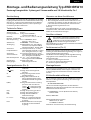
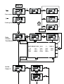
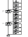
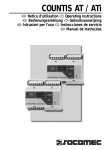
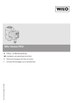
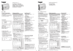
1
66
31
31
62
62
4.5
4,5
27
27
45
8282
6
11
11
30,5
30.5
70
70
9
9
35
35
11,7 ==(58,5)
55xx11.7
[58.5]
9
9
57,7
57.7
22,7
22.7
431951290b
4.5
4,5
69.5
69,5
7
68
68
Pic. 1
Pic. 3
Select
CT
5...30 VDC
Pic. 4
P positive
L1
L2
T
T
CT
Select P(kW )
L1
Class B
L3
Error
U(V)
I(A)
L3
AWD3B5W
L2
L1
k-S1
l-S2
K-P1
L-P2
L2
L3
P+
P negative
L1
3 x 230/400 VAC
L2
L1
L2
L3
N
(PEN)
Pic. 2
L3
L1
L3
Fuse: min. T 250 mA (3×)
Pic. 5
P-
L2
Deutsch
Montage- und Bedienungsanleitung Typ AWD3B5W10
Zweiweg-Energiezähler 3-phasig mit Stromwandler mit S0-Schnittstelle, Pic. 1
Beschreibung
Hinweise vor dem Anschliessen
Energiezähler mit integrierter S0-Schnittstelle für die Übertragung von Messwerten in der Gebäudeautomatisierung.
Über das LC - Display sind zusätzliche Werte wie Momentanleistungen Total oder pro Phase, sowie Spannungen
und Ströme pro Phase abzulesen.
1. Nicht die Phase L1, L2 oder L3 an N anschliessen.
2. Um Feuchtigkeit im Zähler durch Kondenswasser zu
vermeiden, den Zähler vor dem Anschliessen ca. eine
halbe Stunde bei Raumtemperatur akklimatisieren.
3. N muss immer angeschlossen sein.
Achtung!
Diese Geräte dürfen nur durch eine Elektrofachkraft
installiert werden, andernfalls besteht Brandgefahr oder
Gefahr eines elektrischen Schlages!
Technische Daten
Anschlussbild
■ Pic. 2
Abmessungen
■ Pic. 3
Genauigkeitsklasse ■ B gemäss EN50470-3,
1 gemäss IEC62053-21
Referenz-,
■ Iref = 5 A, Imax = 6 A, Ist = 10 mA
Maximal-, Anlaufstrom
Betriebsspannung ■ 3 × 230/400 VAC, 50 Hz
Toleranz −20%/+15%
Zählbereich
■ 000 000,0…9 999 999 kWh
S0-Ausgang
■ Optokoppler max. 30 V /20 mA
und mind. 5 V, Impedanz 100 Ω,
Impulsbreite 30 ms, 10 Imp./kWh
Anschlüsse
■ Leiterquerschnitt 1,5−16 mm2,
Hauptstromkreis Schraubendreher Pozi Nr. 1, Schlitz
Nr. 2, Anzugsmoment 1,5−2 Nm
Anschlüsse
■ Leiterquerschnitt max. 2,5 mm2,
Steuerstromkreis Schraubendreher Pozi Nr. 0, Schlitz
Nr. 2, Anzugsmoment 0,8 Nm
Betriebstemperatur ■
−25… +55 °C (nicht kondensierend gemäss Norm EN50470)
■ Mechanische M2
Umgebungsbedingungen Elektromagnetische E2
Anzeigeelemente (Pic. 4)
T
(kWh)
T
(kWh)
CT
Select
P(kW)
U(V)
I(A)
kWh
L1 / L2 / L3
Error
4 319 5129 0b
Zeigt den totalen Energie■
verbrauch
Zeigt die totale Energierück■
speisung
■
Zeigt das eingestellte Stromwandlerverhältnis
■
Bei geöffneter Brücke Z1-Z2
kann, beim Menupunkt Select,
das Wandlerverhältis eingestellt
werden
■
Zeigt die momentane Leistung
pro Phase oder aller Phasen
Strom « » = Bezug (P positiv)
Strom « » = Rückspeisung (P
negativ)
■ Zeigt die Spannung pro Phase
■ Zeigt den Strom pro Phase
■
Zeigt die Einheit kWh bei
Verbrauchsanzeige
■
Bei P-, U-, I- oder Error-Anzeige
wird die entsprechende Phase
angezeigt
■
Bei fehlender Phase. Die entsprechende Phase wird zusätzlich
angezeigt.
Anschlussschema
Der sekundär, netzseitige Stromwandleranschluss ist mit der zu messenden Phase zu
verbinden und der Stromwandler darf aus
diesem Grund nicht geerdet werden.
Diese Verbindung ist den lokalen Installationsvorschriften
entsprechend abzusichern.
Funktionsweise (Pic. 5)
Energie wird abhängig vom Vorzeichen addiert. Positive
Leistung im Zähler bedeutet Energiebezug, eine negative
Leistung bedeutet Energielieferung.
Die S0-Pulse werden abhängig der Energieflussrichtung
ausgegeben. Diese Funktion kann über das Menu
eingestellt werden.
in = Pulse nur bei Energie Verbrauch
out = Pulse nur bei Energie Rückspeisung
bi = beide Energieflussrichtungen
Montagehinweis
Die 3-Phasen-Energiezähler lassen sich auf eine 35 mm
Schiene (EN60715TH35) aufschnappen. Sie dürfen nur
in dazu geeigneten Installationsschränken verwendet
werden.
EG-Konformitätserklärung
Wir, Saia-Burgess Controls AG, CH 3280 Murten (Schweiz),
erklären in alleiniger Verantwortung, dass die Energiezählerprodukte:
■ AWD3B5W10MC3A00
auf die sich die Erklärung bezieht, mit der Richtlinie
2004/22/EG und den folgenden Normen oder normativen
Dokumenten übereinstimmen:
■ EN50470 Teile 1 und 3 (Elektronische Zähler),
Oktober 2006.
Murten, 30.04.2013
Konformitätsbewertungsstelle:
METAS-Cert, Nr. 1259
CH-3003 Bern-Wabern
Gezeichnet: Jean-Paul Costa, Leiter Entwicklung
07.2013
Änderungen technischer Daten vorbehalten
English
Assembly and operating instructions AWD3B5W10
Three-phase active power bidirectional energy meter with S0-interface, Pic. 1
Description
Notes before connecting
Energy meter with S0-interface for the integrated
transmission of measured values in building automation.
The LC - display add values such as total or instantaneous
power per phase, and read voltages and currents for
each phase.
1. Do not connect L1, L2 or L3 to N
2. In order to avoid moisture in the meter due to condensate build-up, acclimatise the meter at room temperature
for about half an hour before connecting.
3. N must always be connected.
Attention!
These devices must only be installed by a professional
electrician, otherwise there is the risk of fire or the risk of
an electric shock.
Technical data
Connection
■ Pic. 2
diagram
Dimensions
■ Pic. 3
Accuracy class
■ B according to EN50470-3,
1 according to IEC62053-21
Reference, Maxi■ Iref = 5 A, Imax = 6 A, Ist = 10 mA
mum, initial current
operating voltage
■ 3 × 230/400 VAC, 50 Hz
Tolerance −20%/+15%
Counting range
■ 000 000,0…9 999 999 kWh
S0-Ouptut
■ Optocoupler max. 30V/20mA
and min. 5V, impedance 100Ω,
pulse duration 30ms,
10 Imp./kWh
Connections
■ Conductor cross-section 1,5−16 mm2,
Main circuit screwdriver pozi no. 1, slot no. 2,
torque 1,5…2 Nm
Connections
■ Conductor cross-section max. 2,5 mm2,
Control circuit screwdriver pozi no. 0, slot no. 2,
torque 0,8 Nm
Operating
■ −25… +55°C (noncondensing
temperature according standard EN50470)
■ Mechanical M2
Environment
Electromagnetic E2
Indicating elements (Pic. 4)
T
(kWh)
T
(kWh)
CT
Select
P(kW)
U(V)
I(A)
kWh
L1 / L2 / L3
Error
4 319 5129 0b
■ Shows total consumption
■ Shows total feeding back
■
Shows the set current
transformer ratio
■
The transformer ratio can be
selected in Menu item Select, with
the open bridge Z1-Z2
Shows the present output per
■
phase or for all phases
Current « » = supply (P positive)
Current « » = feeding back (P neg.)
■ Shows the voltage per phase
■ Shows the current per phase
Shows the unit kWh when the
■
consumption is displayed
For P-, U-, I- or Error display, the
■
corresponding phase is displayed
In case of missing phase. The cor■
responding phase is additionally
displayed.
Wiring diagram
The secondary, mains current transformer
connection is to be connected to the phase to
be measured and therefore the transformer
don’t have to be grounded.
This connection is to be fused according to the local
installation instructions.
Method of operation (Pic. 5)
Energy is added as indicated by the arithmetic operator.
Positive output in the meter indicates that energy is being
supplied, while negative output indicates that energy is
being delivered.
The S0 pulses are issued depending of the direction of the
energy flow. This function can be set from the menu.
in
= pulses only for energy consumption
out
= pulses only for energy recovery
bi
= both energy flow directions
Installation instructions
The three-phase energy meter can be attached to a 35 mm
rail (EN60715TH35).
The meter can be used only in installation cabinets.
Declaration of Conformity CE
We, Saia-Burgess Controls AG, CH 3280 Murten (Switzerland), herewith declare, on our own responsibility that
the products:
■ AWD3B5W10MC3A00
which this certificate refer to, are in accordance with the
directive 2004/22/EG (MID) and the following standards:
■ EN50470 parts 1 and 3 (electronic meter), of
October 2006.
Murten, 30.04.2013
Conformity Assessment Body:
METAS-Cert, Nr. 1259
CH-3003 Bern-Wabern
Signed: Jean-Paul Costa, Head of development
07.2013
Subject to change without notice
Italiano
Istruzioni d’uso e montaggio Modello AWD3B5W10
Contatore d’energia attiva trifase bidirezionale con interfaccia S0, Pic. 1
Descrizione
Note per il collegamento
Contatori di energia con interfaccia S0 per la trasmissione
integrata dei valori misurati nel «building automation».
Display LCD per visualizzare i valori aggiuntivi come
potenza totale o istantanea per fase, e leggere tensioni e
correnti per ogni fase.
1. Non collegare la fase L1, L2 o L3 a N.
2. Per evitare la presenza di umidità nel contatore in
seguito alla formazione di acqua di condensa, prima del
collegamento lasciare il contatore per circa mezz’ora a
temperatura ambiente
3. N deve sempre essere collegato.
Attenzione!
Questi apparecchi devono essere installati esclusivamente
da elettricisti specializzati, onde evitare rischi di incendio o
pericoli di scosse elettriche!
Dati tecnici
Schema di
■ Pic. 2
collegamento
Dimensioni
■ Pic. 3
d’ingombro
Classe di
■ B secondo EN50470-3,
precisione1 secondo IEC62053-21
Corrente di riferi■ Iref = 5 A, Imax = 6 A, Ist = 10 mA
mento, massima, di spunto
Tensione
■ 3 × 230/400 VAC, 50 Hz
d’esercizio Tolleranza −20%/+15%
Capacità di
■ 000 000,0…9 999 999 kWh
conteggio
Uscita S0
■ Optoisolatore max. 30 V/20 mA
e min. 5 V, impedenza 100 Ω,
ampiezza impulsi 30 ms,
10 Imp./kWh
Morsetti
■ Sezione conduttori 1,5−16 mm2,
circuito principale cacciavite pozi nr. 1, a taglio nr. 2,
coppia di serraggio 1,5−2 Nm
Morsetti
■ Sezione conduttori max. 2,5 mm2,
circuito di comando cacciavite pozi nr. 0, a taglio nr. 2,
coppia di serraggio 0,8 Nm
Temperatura
■ −25…+55°C (assenza di condensa
d’esercizio secondo la norma EN50 470)
■ meccanici M2
Ambienti
elettromagnetici E2
Elementi a display (Pic. 4)
■ indica il consumo totale
■ indica il recupero totale
■
indica il rapporto di
trasformazione di corrente
Select
■
a ponte Z1-Z2 aperto è possibile
di regolare il rapporto di trasformazione di corrente nel menu select
P(kW)
■
Visualizza la potenza istantanea
per fase o di tutte le fasi
Corrente « » = Prelievo (P positiva)
Corrente « » = Immissione (P neg.)
U(V)
■ indica la tensione per ciascuna fase
I(A)
■ indica la corrente per ciascuna fase
kWh
■ indica il consumo rilevato in kWh
L1 / L2 / L3
■ è la fase interessata per P,U,I
o Errore
In caso di mancanza di una fase.
Error
■
Viene visualizzata la fase interessata.
T
(kWh)
T
(kWh)
CT
4 319 5129 0b
Schema di collegamento
Il collegamento secondario del trasformatore
amperometrico, sul lato alimentazione, va
collegato alla fase da misurare e quindi il trasformatore non deve essere messo a terra.
Questo collegamento va messo in sicurezza seguendo le
norme di installazione locali.
Tipo di funzionamento (Pic. 5)
L‘energia verrà sommata in base al segno. La potenza positiva sul contatore indica il prelievo di energia, la potenza
negativa indica l’immissione di energia.
Gli impulsi S0 vengono emessi a seconda della direzione
del flusso di energia.
Questa funzione può essere impostata dal menu.
in = impulsi solo nel consumo di energia
out = impulso solo per il recupero di energia
bi = entrambe le direzioni di flusso di energia
Istruzioni di montaggio
I contatori di energia trifase si installano su guida da
35 mm (EN60715TH35). Devono essere installati solo in
quadri o centralini
Dichiarazione di conformità CE
Noi, Saia-Burgess Controls SA, CH 3280 Morat (Svizzera),
dichiarammo in nostra propria responsabilità che i
prodotti:
■ AWD3B5W10MC3A00
di quali si riferisce questa dichiarazione rispondono alla
direttiva 2004/22/CE (MID) e alle normative seguente:
■ normativa EN50470 Parte 1 e 3
(Contatori elettronici). Octobre 2006
Murten, 30.04.2013
Organismi di valutazione della conformità:
METAS-Cert, Nr. 1259
CH-3003 Bern-Wabern
Firmato: Jean-Paul Costa, capo dello sviluppo
07.2013
Soggetto a modifiche senza preavviso
Francais
Instructions de montage et d’exploitation AWD3B5W10
Compteur d’énergie bidirectionnel active triphasé avec S0-interface, Pic. 1
Description
Remarque préalable au raccordement
Compteurs d‘énergie avec interface S0 intégrée pour la
transmission des valeurs mesurées dans l‘automatisation
du bâtiment. Le LC - display affiche des valeurs additionnelles telles que l‘énergie totale ou instantanée par phase,
ainsi que les tensions et courants pour chaque phase.
1. Ne pas raccorder la phase L1, L2 ou L3 à N.
2. Afin d’éviter la formation de condensation dans le
compteur, laisser celui-ci s’acclimater pendant env. une
demi heure à la température ambiante du local.
3. N doit toujours être connecté.
Attention!
Ces appareils doivent être uniquement installés par un
spécialiste en électricité pour éviter tout risque d’incendie
ou d’électrocution !
Caractéristiques techniques
Schéma de
■ Pic. 2
raccordement
Dimensions
■ Pic. 3
Classe de
■ B selon EN50470-3,
précision 1 selon IEC62053-21
Courant de
■ Iref = 5 A, Imax = 6 A, Ist = 10 mA
référence, maximal, de démarrage
Tension de service ■ 3 × 230/400 VAC, 50 Hz
Tolérance -20%/+15%
Plage de comptage ■ 000000,0 à 9999999 kWh
Sortie S0
■ Optocoupleur max. 30V/20mA
et min. 5V, impédance 100Ω,
largeur d’impulsion 30ms,
10 Imp./kWh
Branchements
■ Section de conducteur 1,5–16 mm2,
Circuit d’alimentation Tournevis Pozi N° 1, plat
N° 2, couple de serrage 1,5–2 Nm
Branchements
■ Section de conducteur maximal
Circuit de commande 2,5 mm2, Tournevis Pozi n° 0, plat
N° 2, couple de serrage 0,8 Nm
Température de
■ –25 à +55°C (sans condensation
service selon la norme EN50470)
■ mécanique M2
Environnement
electromagnétiques E2
Eléments d’affichage (Pic. 4)
T
T
CT
Select
P(kW)
U(V)
I(A)
kWh
L1 / L2 / L3
Error
4 319 5129 0b
Schéma des connexions
Le branchement secondaire côté secteur du
transformateur d’intensité doit être relié à la
phase à mesurer et le transformateur d’intensité
ne doit pas être mis à la terre dans ce cas.
Ce branchement doit être protégé conformément aux
réglementations d’installation locales.
Fonctionnement (Pic. 5)
L‘énergie est ajoutée en fonction du signe. Une puissance
positive signifie une alimentation en énergie, une puissance négative signifie une fourniture d‘énergie.
Les impulsions S0 sont données selon de la direction du
flux énergétique. Cette fonction doit être paramétrée à
partir du menu.
in = impulsions uniquement lors de consommation
out = impulsions uniquement lors de production
d’énergie
bi = impulsions quelle que soit la direction
Instructions de montage
■ Indique la consommation totale
■ Indique la récupération totale
■
Indique le rapport de transformation de courant défini
■
Lors que le pontage Z1-Z2 est ouvert, le rapport de transformation
peut être réglé sous l‘option de
menu Select
■
Affiche la puissance instantanée
par phase ou pour toutes les
phases
Courant « » = Alimentation (P pos.)
Courant « » = Récupération (P nég.)
■ Indique la tension par phase
■ Indique le courant par phase
■
Indique l’unité kWh pour
l’affichage de consommation
■
En cas d’affichage P, U, I ou Error, la
phase correspondante s’affiche
■
En cas d’absence de phase. La
phase correspondante s’affiche
également.
Les compteurs d’énergie triphasé peuvent être encliquetés
sur un rail de 35 mm (EN60715TH35). Ils ne peuvent être
utilisés que dans des armoires électriques.
Déclaration de conformité CE
Nous, Saia-Burgess Controls SA, CH 3280 Morat (Suisse),
déclarons sous notre propre responsabilité que les
produits:
■ AWD3B5W10MC3A00
pour lesquels cette déclaration se référe sont conformes à
la directive 2004/22/CE (MID) et aux normes suivantes:
■ EN50470 Parties 1 et 3 (Compteurs électroniques).
Octobre 2006
Murten, 30.04.2013
Organismes d’évaluation de la conformité:
METAS-Cert, Nr. 1259
CH-3003 Bern-Wabern
Signé : Jean-Paul Costa, Directeur du Développement
07.2013
Sous réserve de modifications sans préavis
Start
CT
Select
CT
Select
>3s
CT
Select
CT
Select
CT
Select
CT
Select
Consumption
Feeding back
> 20 s
Start
CT
CT
Select
Ratio
Current
Transformer (CT)
>3s
Select
CT
Select
bridge Z1-Z2
removed
AWD3B5W10MC_A00
5:5
250:5
750:5
50:5
300:5
1000:5
bridge Z1-Z2
restored
CT
Select
CT
Select
CT
Select
Instan.
Power P
100:5
400:5
1250:5
5 … 1500 A
150:5
500:5
1500:5
200:5
600:5
CT
Select
CT
Select
CT
Select
CT
Select
CT
Select
CT
Select
CT
Select
CT
Select
CT
Select
Voltage
U
Current
I
CT
Select
Start
Saia-Burgess Controls AG
Bahnhofstrasse 18 I CH-3280 Murten I Schweiz
T +41 26 / 672 72 72 I F +41 26 / 672 74 99
www.sbc-support.com