1
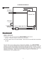
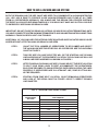
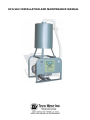
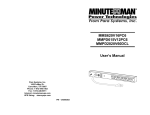
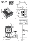
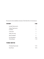
WHISPERAIR DRY VACUUM
INSTALLATION AND SERVICE MANUAL
This manual is for the installation and service of Tech West’s Eco-Vac Dry Vacuums.
CONTENTS
PAGE
Location Requirements
1
Voltage Requirements
1
Installation
2
Connections
3
Weekly Servicing
3
Motor Breakdown
4
Parts Breakdown
5-10
Wiring Diagram
11-12
TROUBLE SHOOTING
Plumbing Requirements
13-14
Note Sheets
15-16
WHISPERAIR DRY VACUUM
INSTALLATION
1 -1.
Eco-Vac
Location DRY
Requirements
WHISPERAIR
VACUUM
LOCATION REQUIREMENTS
The Eco-Vac Dry Vacuum location should be level, accessible and well ventilated.
If the Eco-Vac Dry Vacuum will be located in a confined space, provide adequate ventilation and
install an exhaust fan. THE EXHAUST VENT ON THE VACUUM UNIT MUST BE CONNECTED TO A
LOCATION OUTSIDE OF THE EQUIPMENT LOCATION. THE CONNECTION SHOULD BE MADE
WITH STEEL OR COPPER PIPE.
The following utilities are required:
(a) Waste Disposal THE VACUUM SYSTEM MUST BE INSTALLED SO THAT THE DRAIN
ON THE SIDE OF THE UNIT IS HIGHER THAT THE WASTE CONNECTION. THIS WILL
ALLOW THE UNIT TO GRAVITY DRAIN WHEN THE SUCTION IS SHUT OFF. Provide a
floor sink or trapped sewer line to connect the 1 1/4” PVC flex hose included in the hook-up
kit. Provide exhaust vent sized according to table 1 below and waste drain that complies
with local code.
(b) Vacuum Line The main vacuum line from the operatories must connect to the Eco-Vac.
Connect to the piping using the 1 1/4” PVC hose provided in the hook-up kit.
(c) Electrical-
CAUTION:
“possible ground leakage current present”
“présent de courant de fuite de terre possible”
(1) Line voltage must be within the limits of table 2 below. (Install a “buck-boost
transformer” if the line voltage is not between these values.) Circuit breaker
switches must be 20 amp minimum on singles and 30 amp on duals.
(2) Local code may require you to provide a quick disconnect (safety switch) for
the vacuum unit.
(3) The WhisperAir is controlled by a 24 volt circuit. For remote switching, provide one
18/3 jacketed cable for the switching on and off each unit. (Dual units need two
sets of 18/3 jacketed cable.
TABLE 1
Pump Size
Single
Exhaust Vent (dia)
Dual
2”
2”
TABLE 2
Pump Voltage
Amperage Draw
Min. Line Voltage
Max. Line Voltage
230 V Single Motor
12amps
208 V constant
245 V constant
230 V Dual Motor
24 amps
208 V constant
245 V constant
1
WHISPERAIR DRY VACUUM
INSTALLATION
2
2. INSTALLATION STEPS
This dry vacuum unit should only be installed by qualified personnel. Should any questions arise
during the installation, call Tech West Technical Support between the hours of 7:00 a.m. to 4:00 p.m.
(Pacific Standard Time).
Place the dry vacuum in a clean, dry, well ventilated area, on a solid, level surface. Be sure that
adequate ventilation is available and install an exhaust fan. Ambient temperature in the equipment
room should be within the temperature range of 40 degrees Fahrenheit minumum to 100 degrees
Fahrenheit maximum.
(a) Check the shipping carton for damage. This could detect damage to the unit which might
otherwise be overlooked. Remove cardboard shipping carton.
(b) Remove the Vacuum from its shipping carton. Inspect the unit for damage.
Dry vacuums are shipped bolted to a pallet. This pallet is intended for shipping only and
should be discarded.
(c) Inventory your hook-up kit. Check its contents against the inventory sheet included. These
items will be used in the remaining steps.
(d) Install rubber mounting feet on under side of unit.
(e) Mount the separator tank onto the top of the steel frame with the bolts provided.
(f) Connect the suction hose from top of the tank to the vacuum with the flex hose provided.
(g) Make the necessary exhaust vent connections. (WARNING: Exhaust must be vented with a
metalic pipe for the first 10 feet)
(h) Connect the main vacuum line. Connect flexible 1 1/4” hose to the side of seperator tank.
(i) Connect remote control 18/3 jacketed cable to the relay panel. Use wire connectors
that provide secure mechanical connections.
(j) Connect line voltage (via safety switch if required by local code). Refer to the wiring diagram.
(k) Turn on the Vacuum. Check the pump(s) for leaks and the vacuum level following
the instructions on “Weekly Servicing”.
2
WHISPERAIR DRY VACUUM
PLUMBING SCHEMATIC
2
3. CONNECTIONS
Air out to
vacuum producer
Main vacuum line
from operatories.
1 1/4 PVC connection
Separator Tank
Exhaust vent line
1 1/2” steel for single,
2” for dual
*
* CAUTION - Use steel or copper pipe to make this connection
*
*
Waste Aline 1 1/4
PVC connection
Check
valve
Gravity drain line
3. WEEKLY SERVICING
PERIODIC SERVICING
WEEKLY SERVICING
(a) Flush the main vacuum lines with a NON-FOAMING dental vacuum
cleanser. Follow the cleanser manufacturers instructions.
(b) Visually inspect Vacuum for water leakage. Ensure that all hoses and water connections
are tight.
Flush the entire vacuum piping system (all operatories) weekly. Use a NON-FOAMING
cleanser. It is extremely important that the cleaner used cannot and will not foam. Foam will
get sucked into the vacuum producer and will cause damage over time. If the Vacuum can
not induce adequate air flow because of a blockage in the vacuum piping system, liquids and
solids will not evacuate. Contact Tech West’s Technical Support for further details on
maintaining your vacuum piping system.
3
3
1
2
5
4
SINGLE ELECTRICAL PANEL PARTS BREAKDOWN
KEY
PART NO.
DESCRIPTION
1
PT-100
TRANSFORMER 24V
1
2
PR-100
RELAY / CONTRACTOR
1
3
TS3
THREE POSITION TERMINAL STRIP
1
4
TS6
SIX POSITION TERMINAL STRIP
1
5
PRBI-DV
RELAY PANNEL ONLY
1
9
UNIT
HOW TO SIZE A VACUUM AND AIR SYSTEM
BOTH THE DRAWING AND THE SIZE CHART ARE SIZED TO ACCOMMODATE A VACUUM SYSTEM FOR
100% USE. tHIS IS DONE TO PRODUCE GOOD VACUUM PRESSURES AND FLOWS AT ALL TIMES
FROM ALL OPERATORIES. NORMALLY, YOU ALWAYS USE THIS DESIGN FOR A PROPER SYSTEM IN
THE EVENT ALL SIX ARE USED SIMULTANEOUSLY; YOU WOULD NOT HAVE ANY SUCTION LOSS DUE
TO IMPROPERLY SIZED MAIN OR BRANCH LINES.
IMPORTANT: DO NOT FIGURE OR DRAW ANY NITROUS OR SINK EVACUATION TERMINATIONS UNTIL
YOU HAVE A COMPLETE SYSTEM SHOWING TERMINATION TO HIGH VOLUME EVACUATION CONNECTIONS
NORMALLY FOUND IN DENTAL UNIT JUNCTION BOX.
ADDITIONAL 3/4” VACUUM LINES FOR NITROUS OXIDE SCAVENGE AND EVACUATOR SINKS CAN BE
ADDED WITHOUT AFFECTING MAIN OR BRANCH LINE SIZES.
STEP 1.
COUNT THE TOTAL NUMBER OF OPERATORIES TO BE PLUMBED AND SELECT
THE VACUUM LINE SIZE FOR EITHER PVC OR COPPER PIPE. SEE THE LINE SIZING
CHART IN FIGURE 2
STEP 2.
THIS PIPE SIZE YOU HAVE SELECTED WILL BE THE STARTING LINE OR MAIN
LINE AND BEGINS AT THE EQUIPMENT LOCATION. THE VACUUM LINE WILL USE
A MAIN LINE RISER ASSEMBLY AS SHOWN IN FIGURES 1.
STEP 3.
AFTER FIGURING YOUR MAIN LINE SIZE, YOU MAY SELECT THE BEST LOCATION
TO SPLIT YOUR PIPING LINES TO BEST ACCOMMODATE THE OPERATORIES.
EACH ZONE BECOMES ITS OWN SYSTEM FOR PURPOSES ON SIZING THE LINES
PROPERLY. IF OPERATORIES ARE IN A STRAIGHT LINE, ZONE SPLITTING WILL
NOT BE REQUIRED.
STEP 4.
STARTING FROM ZONE SPLIT LOCATION, COUNT REMAINING OPERATORIES
AND LOOK AT THE SIZING CHART IN FIGURE 2 SELECT CORRECT BRANCH
LINE DIAMETER.
FIG. 2. VACUUM LINE SIZING CHART
NUMBER OF
OPERATORIES
SEE NOTE
VACUUM LINE
PIPE DIAMETER
PVC sch 40
COPPER TYPE “M”
1
1 1/4”
1”
2
1 1/4”
1”
3
1 1/4”
1 1/4”
4
1 1/2”
1 1/2”
5
1 1/2”
1 1/2”
6
2”
1 1/2”
7
2”
1 1/2”
8
2”
1 1/2”
13
NOTES
1.
HANGER SUPPORTS REQUIRED EVERY
EIGHT FEET OR TO SUPPORT PIPING
WITHOUT SAGS.
2.
ALWAYS STUB VACUUM AND AIR LINE INTO
WALL OR FLOOR JUNCTION BOX PER
MANUFACTURER’S TEMPLATE. IF 1/2” IS
REQUIRED, YOU MAY REDUCE PIPE SIZE
AS CLOSE AS POSSIBLE TO TERMINATION
POINT. IT A LARGER SIZE IS REQUIRED, THIS
CHANGE MUST BE MADE WITHIN JUNCTION BOX.
3.
ALL VACUUM PIPING ILLUSTRATIONS AND
DRAWINGS ARE SHOWN WITH PVC PIPE SCH
40 AND DWV TYPE FITTINGS. ALWAYS USE
SWV FITTINGS. NOT AVAILABLE
BELOW 1 1/4”.
4.
ALL VACUUM PIPING SHOULD GRADE
TOWARD EQUIPMENT LOCATION 1/4” IN
TEN FEET.
5.
WHEN INSTALLING AN OVERHEAD SYSTEM,
USE THE NEXT LARGER VACUUM PUMP
MODEL FOR BEST RESULTS.
6.
INSTALL TRAP IN MAIN LINE JUST BEFORE
HOOKING THE FLEXIBLE INTAKE HOSE
CONNECTION TO PUMPS. SEE FIG. 1,
EXAMPLE B.
7.
IN AN OVERHEAD SYSTEM, THE MAIN
VACUUM LINE WILLDROP DOWN TO THE
DRY-VAC LOCATION USING REQUIRED
PIPE SIZE. ALL OVERHEAD SYSTEMS ARE
SIZED IN THE SAME MANNER AS THE
SYSTEM SHOWN HERE.
8.
DO NOT RUN POLY FLO TUBING BELOW
SLAB. ALWAYS RUN PIPE UP ABOVE SLAB,
THEN MAKE POLY FLO CONNECTION.
9.
FIG. 2 LINE SIZING CHART SHOWS MAIN
VACUUM LINE SIZE DIAMETER FOR 4, 5 AND
6 OPERATORIES AS 1 1/2” DIAMETER.
IF 1 1/2: DIAMETER IS NOT AVAILABLE, YOU
MAY USE 2” DIAMETER.
10. RISER ASSY. MUST ALWAYS BE USED. SEE
FIG. 1 EXAMPLE A FOR RISER ASSY. SPECI
FICATIONS.
11. CONTROL PANEL SUPPLY LINES SHOULD BE
CONNECTED CLOSE TO EQUIPMENT ROOM
AND MUST ALWAYS CONNECT VERTICALLY
TO MAIN LINE AS SHOWN.
14
Maintenance & Service / Notes
15
Maintenance & Service / Notes
16
TECH WEST INC.
Manufacturers of Dental Vacuum
and Air Systems
2625 N Argyle Ave. • Fresno, CA 93727
(559) 291-1650 • (800) 428-7139 • FAX (559) 348-9677
ECO-VAC INSTALLATION AND MAINTENANCE MANUAL