1
INSTALLATION AND USER’S MANUAL
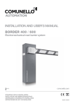
BORDER 400 / 600
Electromechanical road barrier system
comunello.com
ISTRUZIONI D’USO E DI INSTALLAZIONE
INSTALLATIONS-UND GEBRAUCHSANLEITUNG
INSTRUCIONS D’UTILISATION ET D’INSTALLATION
INSTRUCCIONES DE USO Y DE INSTALACION
ИНСТРУКЦИЯ ПО МОНТАЖУ
Rev. 00 - .02.07.14
FIG. 1A
BORDER 400
286
320
220
789
822
1031
FIG. 1B
BORDER 600
335
420
789
1031
837
250
2
COMUNELLO ®Copyright 2014 - All right reserved
FIG. 2
FIG. 3A
FIG. 3B
COMUNELLO ®Copyright 2014 - All right reserved
3
FIG. 4
FIG. 5
FIG. 7
FIG. 6
4
COMUNELLO ®Copyright 2014 - All right reserved
FIG. 8A
FIG. 9A
FIG. 8B
FIG. 9B
COMUNELLO ®Copyright 2014 - All right reserved
5
FIG. 9C
FIG. 10A
FIG. 10B
FIG. 11
6
COMUNELLO ®Copyright 2014 - All right reserved
FIG. 12A
FIG. 13A
FIG. 12B
FIG. 13B
FIG. 13A
FIG. 14
FIG. 15
COMUNELLO ®Copyright 2014 - All right reserved
7
ISTRUZIONI D’USO E DI INSTALLAZIONE
BORDER 400 / 600
DICHIARAZIONE DEL FABBRICANTE
Fratelli Comunello Spa
Via Cassola 64, 36027 Rosà (VI) - Italia
Fabbricante: Indirizzo: Dichiara che l’automazione elettromeccanica per barriera modello BORDER:
• è costruita per essere incorporata in una macchina o per essere assemblata con altri macchinari per costituire una macchina considerata
dalla Direttiva 98/37 CE;
• è conforme alle condizioni delle seguenti altre Direttive CE:
Direttiva bassa tensione 2006/95 CE e successivi emendamenti secondo la normativa armonizzata EN 60335-1
Direttiva compatibilità elettromagnetica 2004/108/CE e successivi emendamenti secondo le normative EN 61000-6-2 e EN 61000-6-3
• è conforme alle normative EN 301489-1, EN 301489-3, EN 300220-2, EN 622233, EN 13241-1, EN 12445, EN 12453.
Inoltre dichiara che non è consentito mettere in servizio il macchinario fino a che la macchina in cui sarà incorporata o di cui diverrà
componente sia stata identificata e ne sia stata dichiarata la conformità alle condizioni della Direttiva 98/37 CE e alla legislazione nazionale
che la traspone.
Luca Comunello
Rappresentante legale della Fratelli Comunello
Fratelli Comunello S.p.A.
Azienda con Sistema Gestione Qualità certificato
UNI EN ISO 9001:2008.
(Certificato n° 50 100 11235 Rev. 01)
8
COMUNELLO ®Copyright 2014 - All right reserved
1
AVVERTENZE GENERALI
1.1 Avvertenze per la sicurezza
1.2 Avvertenze per l’installazione
1.3 Avvertenze per l’uso
2
MODELLI E DESCRIZIONE PRODOTTO
2.1Descrizione
2.2 Installazione tipica
3
CARATTERISTICHE TECNICHE DEL PRODOTTO
4INSTALLAZIONE
4.1 Verifiche preliminari
4.2 Limiti d’impiego
4.3 Lavori di predisposizione all’installazione
4.4 Installazione dell’alzabarriera mod. BORDER
4.4.1Installazione
4.4.2 Regolazione finecorsa finecorsa
4.4.3 Sblocco manuale
5
PREDISPOSIZIONE AI COLLEGAMENTI ELETTRICI
6COLLAUDO
7
MANUTENZIONE DEL PRODOTTO
8RICAMBI
9
SMALTIMENTO DEL PRODOTTO
10
SCHEDA ELETTRONICA
10.1Avvertenze
10.2 Caratteristiche tecniche
10.3 Collegamenti elettrici
10.4 Caratteristiche funzionali
10.5Programmazione
1 AVVERTENZE GENERALI
sostanze nocive dalla batteria opzionale è preferibile estrarla e custodirla
in luogo asciutto.
• Collegare la centrale solo ad una linea di alimentazione elettrica dotata
di messa a terra di sicurezza.
•Tutte le operazioni che richiedono l’apertura dell’alzabarriera
BORDER devono avvenire con la centrale di comando scollegata e
dall’alimentazione elettrica; se il dispositivo di sconnessione non è a
vista apporvi un cartello: “ATTENZIONE MANUTENZIONE IN CORSO”.
• Qualora si verifichino interventi di interruttori automatici o di fusibili, prima
di ripristinarli è necessario individuare ed eliminare il guasto.
• Nel caso di guasto non risolvibile facendo uso delle informazioni riportate
nel presente manuale, interpellare il servizio di assistenza.
2 MODELLI E DESCRIZIONE DEL PRODOTTO
2.1 DESCRIZIONE
Di robusta fabbricazione e facile installazione l’alzabarriere elettromeccanico
BORDER è adatto ad un uso privato, pubblico e industriale. Grazie alla
centrale elettronica on board è possibile programmare qualsiasi funzione
utile ad un’alzabarriera.
2.2 INSTALLAZIONE TIPICA
D
E
C
B
A
1.1 AVVERTENZE PER LA SICUREZZA
Il presente manuale di installazione è rivolto esclusivamente a personale
professionalmente competente. È necessario leggere tutte le istruzioni
prima di procedere all’installazione. Tutto quello che non è espressamente
previsto in queste istruzioni non è permesso; usi non previsti potrebbero
essere fonte di danni al prodotto e mettere in pericolo persone e cose.
Il costruttore declina qualsiasi responsabilità dall’inosservanza della buona
tecnica nella costruzione delle barriere, nonché delle deformazioni che
potrebbero verificarsi durante l’uso. Conservare questo manuale anche
per utilizzi futuri. La progettazione, la fabbricazione dei dispositivi che
compongono BORDER ed il presente manuale rispettano pienamente
la norma vigente. Considerando le situazioni di rischio che possono
verificarsi durante l’installazione e l’uso di BORDER e necessario che anche
l’installazione avvenga nel pieno rispetto di leggi, norme e regolamenti; in
particolare:
1.2 AVVERTENZE PER L’INSTALLAZIONE
• Prima di iniziare l’installazione verificare la necessità di ulteriori dispositivie
materiali che possono servire a completare l’automazione con BORDER
in base alla specifica situazione d’impiego.
• L’automatismo non deve essere utilizzato prima di aver messo in
sicurezza l’area di passaggio.
• Il materiale dell’imballaggio deve essere smaltito nel pieno rispetto della
normativa locale.
1.3 AVVERTENZE PER L’USO
• Non eseguire modifiche su nessuna parte se non previste nel
presente manuale. Operazioni di questo tipo possono solo causare
malfunzionamento. Il costruttore declina ogni responsabilità per danni
derivati da prodotti modificati.
• Evitare che le parti dell’automatismo possano venir immerse in acqua
o in altre sostanze liquide. Anche durante l’installazione evitare che
parti solide o liquidi possano penetrare all’interno della centrale e di altri
dispositivi aperti.
• Qualora sostanze liquide siano penetrate all’interno dei dispositivi
dell’automatismo, scollegare immediatamente l’alimentazione elettrica e
rivolgersi al servizio di assistenza; l’uso di BORDER in tali situazioni può
causare situazioni di pericolo.
• Non tenere qualsiasi componente di BORDER vicino a fonti di calore né
esporlo a fiamme; tali azioni possono danneggiarlo ed essere causa di
malfunzionamenti, incendio o situazioni di pericolo.
• Nel caso di lunghi periodi di inutilizzo, per evitare il rischio di perdite di
B
LEGENDA
A ALZABARRIERA CON CENTRALINA INTERNA
BFOTOCELLULE
C LAMPEGGIANTE
D SELETTORE A CHIAVE
E APPOGGIO ASTA
3 CARATTERISTICHE TECNICHE DEL
PRODOTTO
BORDER 400
Alimentazione motore
Potenza assorbita
Assorbimento
Coppia
Intermittenza di lavoro
Grado di protezione
Classe di isolamento
Temp. di funzionamento
Peso
BORDER 600
24 Vdc
150 W
6,5 A
100 Nm
100 Nm
Intensivo
IP 24 D
1(Messa a terra)
da -20°C a + 50°C
65 Kg
65 Kg
4 INSTALLAZIONE
4.1 VERIFICHE PRELIMINARI
Per un corretto funzionamento dell’automazione verificare quanto segue:
• Tutti gli accessori siano adeguatamente dimensionati.
• Verificare che sia possibile rispettare tutti i limiti d’impiego del prodotto.
• Siano rispettati gli spazi minimi e massimi riportati nelle figure (FIG.1A,
FIG. 1B)
• Tutto il materiale da utilizzare sia in ottimo stato e adatto all’uso previsto.
• L’ambiente scelto per l’installazione sia compatibile con l’ingombro totale
del prodotto.
COMUNELLO ®Copyright 2014 - All right reserved
9
ITALIANO
INDICE
• Lungo la traiettoria del movimento dell’asta non vi siano ostacoli che
possano impedire le manovre di apertura e chiusura.
• La superficie di appoggio dell’alzabarriera garantisca un fissaggio stabile.
• Lo spazio circostante all’alzabarriera non impedisca una facile e sicura
esecuzione delle manovre manuali.
• Verificare che ciascun dispositivo da installare sia collocato in una
posizione protetta e al riparo da urti accidentali.
• Prevedere se necessario un accesso pedonale al di fuori della zona di
manovra dell’asta
4.2 LIMITI D’IMPIEGO
• Sopra i 3 metri di lunghezza utilizzare l’appoggio asta
• Se si desidera installare la siepe questa non deve superare i 4 metri
Prima di eseguire l’installazione della barriera, verificare che i suoi dati
rientrino nei limiti d’impiego nel capitolo “Caratteristiche tecniche del
prodotto”
4.3 LAVORI DI PREDISPOSIZIONE ALL’INSTALLAZIONE
• Assemblare la contropiastra con i tirafondi (FIG. 2)
• Immergere la contropiastra con i tirafondi nel cemento (FIG.3A)
• Nel caso di cemento già esistente effettuare 4 fori per i tasselli come
illustrato in FIG. 3B.
4.4 INSTALLAZIONE DELL’ ALZABARRIERA BORDER
4.4.1 INSTALLAZIONE:
• Togliere la copertura frontale mediante l’utilizzo della chiave in dotazione
(FIG. 4)
• Appoggiare l’alzabarriera sulla contropiastra facendo passare i cavi
di alimentazione e degli accessori attraverso il foro di passaggio cavi.
Fissarla con i dadi e rondelle in dotazione (FIG. 5)
Assemblaggio asta:
• Ove previsto attaccare la striscia adesiva LED nell’apposito canale lungo
tutta le lunghezza della barra (FIG. 6)
• Inserire la guaina paracolpi nelle apposite guide fermandosi ad una
distanza di 175 mm dall’estremità opposta FIG. 7.
Nel caso di asta tonda non è previsto l’utilizzo della gomma paracolpi
• Fissare il tappo ad un’estremità dell’asta come illustrato in FIG. 8A / 8B.
Installazione asta:
• Sbloccare il motore come descritto nel paragrafo 4.4.3
• Fissare il supporto asta al perno in uscita nella parte posteriore del
telaio assicurandosi che il supporto sia in posizione di “asta orizzontale”
(FIG. 9A, FIG. 9C) e che il meccanismo interno sia nella posizione
illustrata in FIG. 9B. Utilizzare il frenafiletti nelle 4 viti centrali.
• Assicurarsi che l’asta sia inserita completamente all’interno del supporto.
• Chiudere il supporto con il coperchio (FIG. 9A, FIG. 9B, FIG. 9C).
Assemblaggio delle molle:
• Se bloccata sbloccare l’alzabarriera come illustrato nel cap. 4.4.3
• Mettere in posizione verticale l’asta (FIG. 11)
• Fissare sopra e sotto la molla (singola o doppia) come illustrato nelle
FIG. 12A e 12B.
• Assicurarsi che, ad installazione effettuata, l’asta sia controbilanciata
dalla molla come rappresentato in FIG. 14
• Scegliere la molla adatta consultando la seguente tabella
BORDER 400
ASSEMBLAGGIO ASTA
E SCELTA DI BILANCIAMENTO
LUNGHEZZA UTILE (m)
1,5 2,0 2,5 3,0 3,5 4,0
Asta
Asta con kit guaina
Asta con kit guaina e led
Asta con appoggio mobile
Asta con kit guaina e appoggio mobile
Asta con kit guaina, led e appoggio mobile
Asta con siepe
Asta con guaina superiore, siepe
Asta con guaina superiore, led e siepe
Asta con guaina superiore, led,
siepe e appoggio mobile
Molla piccola AC 530
Molla media AC 540
10
COMUNELLO ®Copyright 2014 - All right reserved
BORDER 600
ASSEMBLAGGIO ASTA
E SCELTA DI BILANCIAMENTO
LUNGHEZZA UTILE (m)
2,0 2,5 3,0 3,5 4,0 4,5 5,0 5,5 6,0
Asta
Asta con kit guaina
Asta con kit guaina e led
Asta con appoggio mobile
Asta con kit guaina e appoggio mobile
Asta con kit guaina, led e appoggio mobile
Asta con siepe
Asta con guaina superiore, siepe
Asta con guaina superiore, led e siepe
Asta con guaina superiore, led,
siepe e appoggio mobile
Molla piccola AC 530
Molla media AC 540
Regolazione del tiraggio molle:
A motore sbloccato (paragrafo 4.4.3) portare manualmente l’asta a circa
metà della sua corsa (45°) FIG. 14 e lasciarla ferma. Se l’asta tende a
salire oppure a scendere, è necessario agire sulla regolazione della molla,
ruotandola.
4.4.2 REGOLAZIONE FINECORSA
L’alzabarriera BORDER è fornito di finecorsa elettromeccanici.
È importante assicurarsi che la regolazione del dado consenta comunque
l’azionamento dei finecorsa.
Per regolare i bulloni proseguire come segue:
• Sbloccare l’asta come descritto nel cap. 4.4.3
• Agire svitando o avvitando il bullone sulla piastra come illustrato in
FIG. 13A
• Bloccare i bulloni con i controdadi
4.4.3 SBLOCCO MANUALE
• Per sbloccare e consentire un movimento manuale della barriera aprire
uno dei due sportellini laterali e girare in senso nella direzione della
freccia la maniglia come illustrato in FIG. 13B.
5 PREDISPOSIZIONE AI COLLEGAMENTI
ELETTRICI
• Togliere la copertura frontale mediante l’utilizzo della chiave in dotazione
(FIG. 4)
• Collegare il filo giallo/verde (messa a terra) al capocorda ad occhiello
• Portare i fili elettrici alla scheda elettronica.
6 COLLAUDO
Per il collaudo di BORDER eseguire la seguente sequenza di operazioni:
• Verificare che sia stato rispettato rigorosamente tutto quanto previsto nel
presente manuale ed in particolare nel capitolo 1 “Avvertenze generali”;
• Utilizzando i dispositivi di comando o arresto previsti (selettore a
chiave, pulsanti di comando o trasmettitori radio), effettuare delle
prove di apertura, chiusura ed arresto della barriera e verificare che il
comportamento corrisponda a quanto previsto.
• Verificare uno ad uno il corretto funzionamento di tutti i dispositivi di
sicurezza presenti nell’impianto (fotocellule, bordi sensibili, arresto di
emergenza, ecc.).
7 MANUTENZIONE DEL PRODOTTO
La manutenzione deve essere effettuata regolarmente da parte di personale
qualificato secondo quanto previsto dalle leggi e normative vigenti. Per
BORDER è necessaria una manutenzione programmata al massimo entro
6 mesi dalla precedente manutenzione.
• Scollegare qualsiasi fonte di alimentazione dal motore
• Verificare e sostituire tutte le parti di movimento usurate
• Verificare lo stato di deterioramento di tutte le parti dell’automazione.
È possibile acquistare dei particolari di ricambio, in caso di tale necessità
contattare l’assistenza tecnica.
9SMALTIMENTO
Al termine della vita dell’automazione, assicuratevi che lo smantellamento
sia eseguito da personale qualificato e che i materiali vengano riciclati o
smaltiti secondo le norme valide a livello locale.
10 SCHEDA ELETTRONICA
10.1 AVVERTENZE
• La centrale non presenta nessun tipo di dispositivo di sezionamento
della linea elettrica 230 Vac, sarà quindi cura dell’in stallatore prevedere
nell’impianto un dispositivo di sezionamento. È necessario installare un
interruttore omnipolare con categoria III di sovratensione. Esso deve
essere posizionato in modo da essere protetto contro le richiusure
accidentali secondo quanto previsto al punto 5.2.9 della EN 12453. Il
cablaggio dei vari componenti elettrici esterni alla centralina deve essere
effettuato secondo quanto prescritto dalla normativa EN 60204-1 e
dalle modifiche a questa apportata dal punto 5.2.7 della EN 12453.
I cavi di alimentazione possono avere un diametro massimo di 14 mm;
il fissaggio dei cavi di alimentazione e di collegamento, deve essere
garantito tramite l’assemblaggio di pressacavi fornibili “optional”.
• Utilizzare in fase di installazione esclusivamente cavi in doppio isolamento
(cavi con guaina) sia per i collegamenti a tensione di rete (230V) che
per i collegamenti in bassissima tensione di sicurezza SELV. Utilizzare
esclusivamente canalette in plastica, distinte per i cablaggi in bassa
tensione (230V) e per i cablaggi in bassissima tensione di sicurezza
(SELV).
• I conduttori a bassissima tensione di sicurezza devono essere
fisicamente separati (almeno 4 mm in aria) dai conduttori a tensione
di rete, oppure devono essere adeguatamente isolati con isolamento
supplementare avente spessore di almeno 1 mm.
• Prevedere a monte della rete di alimentazione dell’automazione un
dispositivo che assicuri la disconnessione completa omnipolare della
rete, con una distanza di apertura dei contatti in ciascun polo di almeno
3mm. Tali dispositivi di disconnessione devono essere previsti nella rete
di alimentazione conformemente alle regole di installazione e devono
essere direttamente collegati ai morsetti di alimentazione.
• Per i cavi di alimentazione si raccomanda di utilizzare cavi flessibili sotto
guaina isolante in policloroprene di tipo armonizzato (H05RN-F) con
sezione minima dei conduttori pari a 1mm2.
• Fare attenzione, in fase di foratura dell’ involucro esterno per far passare
i cavi di alimentazione e di collegamento, e di assemblaggio dei
pressacavi, ad installare il tutto in modo da mantenere il più possibile
inalterate le caratteristiche di grado IP della scatola. Prestare inoltre
attenzione a fissare i cavi in modo che siano ancorati in modo stabile.
• L’involucro nella parte posteriore è provvisto di opportune predisposizioni
per fissaggio a muro (predisposizione per fori per fissaggio mediante
tasselli o fori per fissaggio mediante viti). Prevedere e implementare tutti
gli accorgimenti per una installazione che non alteri il grado IP.
• L’eventuale montaggio di una pulsantiera per il comando manuale deve
essere fatto posizionando la pulsantiera in modo che l’utente non venga
a trovarsi in posizione pericolosa.
• Il motoriduttore usato per muovere il cancello deve essere conforme a
quanto prescritto al punto 5.2.7 della EN 12453.
• L’uscita FOTO+ è necessariamente dedicata all’alimentazione delle
fotocellule, non è consentito l’utilizzo per altre applicazioni.
• La centrale ad ogni ciclo di manovra può effettuare il test di
funzionamento delle fotocellule, garantendo una protezione al guasto
dei dispositivi antischiacciamento di Categoria 2 secondo quanto
prescritto al punto 5.1.1.6. della EN 12453. Quindi se i dispositivi di
sicurezza non vengono connessi e/o non sono funzionanti la centrale
non è abilitata al funzionamento.
• L’apparecchio può essere utilizzato da bambini di età non inferiore a
8 anni e da persone con ridotte capacità fisiche, sensoriali o mentali,
o prive di esperienza o della necessaria conoscenza, purché sotto
sorveglianza oppure dopo che le stesse abbiano ricevuto istruzioni
relative all’uso sicuro dell’apparecchio e alla comprensione dei pericoli
ad esso inerenti. I bambini non devono giocare con l’apparecchio. La
pulizia e la manutenzione destinata ad essere effettuata dall’utilizzatore
non deve essere effettuata da bambini senza sorveglianza.
Per un corretto funzionamento della parte radio ricevente, in caso di utilizzo
di due o più centrali, si consiglia l’installazione ad una distanza di almeno 3
metri l’una dall’altra.
Tutte le operazioni che richiedono l’apertura dell’involucro (collegamento
cavi, programmazione, ecc.) devono essere eseguite in fase di installazione
da personale esperto.
IMPORTANTE PER L’UTENTE
• Il dispositivo non deve essere utilizzato da bambini o da persone con
ridotte capacità psico-fisiche, almeno che non siano supervisionati o
istruiti sul funzionamento e le modalità di utilizzo.
• Non consentire ai bambini di giocare con il dispositivo e tenere lontano
dalla loro portata i radiocomandi.
• ATTENZIONE! conservare questo manuale d’istruzioni e rispettare le
importanti prescrizioni di sicurezza in esso contenute. Il non rispetto
delle prescrizioni potrebbe provocare danni e gravi incidenti.
Esaminare frequentemente l’impianto per rilevare eventuali segni di
danneggiamento. Non utilizzare il dispositivo se è necessario un intervento
di riparazione.
10.2 CARATTERISTICHE TECNICHE
Ingresso Batteria d’emergenza:
Uscita lampeggiante:
Uscite motori:
Alimentazione fotocellule:
Temperatura d’esercizio:
Ricevitore radio:
Trasmettitori op.:
Codici TX max. in memoria:
Dimensioni scheda:
24 V 7A/h max.
24 V 4 W max.
24V 1 x 50 W max.
24V 5 W max.
-20 ÷ 55 °C
433 Mhz
18 Bit o Rolling Code
120 (CODE o CODE PED)
100x105 mm.
10.3 COLLEGAMENTI ELETTRICI
CN1:
BATT+24V:
BATT-24V:
LAMP+24V:
LAMP-24V:
MOT1+:
MOT1-:
CN2:
STOP: GND: FOTO+:
GND:
FCC:
GND:
FCA:
DS1:
GND:
PP:
ANT-:
ANT+:
CN3:
L:
N:
Ingresso +24V Batteria d’emergenza
Ingresso – 24V Batteria d’emergenza.
Uscita + 24V Lampeggiante.
Uscita – 24V Lampeggiante.
Uscita + Motore 1.
Uscita - Motore 1.
Ingresso Blocco (NC).
Ingresso GND comune.
Controllo e Alimentazione Fotocellule (24V 5W).
Controllo e Alimentazione Fotocellule (GND).
Ingresso Finecorsa Chiusura Motore (NC).
Ingresso GND comune
Ingresso Finecorsa Apertura Motore (NC).
Ingresso Dispositivo Sicurezza (NC).
Ingresso GND comune
Ingresso Pulsante P/P comando apre-chiude (NA).
Ingresso Massa Antenna.
Ingresso Polo caldo Antenna.
Ingresso linea 230 V
Ingresso linea 230 V
(Fase).
(Neutro).
10.4 CARATTERISTICHE FUNZIONALI
FUNZIONAMENTO:
Utilizzando sia il radiocomando che la pulsantiera in bassa tensione per
l’azionamento del serramento, si otterrà il seguente funzionamento:
il primo impulso comanda l’apertura fino allo scadere del tempo motore o
al raggiungimento del fine corsa d’apertura, il secondo impulso comanda
la chiusura della barriera; se si invia un impulso durante la fase di Apertura,
la centrale Ignora il comando, se si invia un impulso durante la fase di
Chiusura la centrale effettua l’inversione del moto.
CHIUSURA AUTOMATICA:
La centrale permette di richiudere la barriera in modo automatico senza
l’invio di comandi supplementari.
La scelta di questo funzionamento è descritta nel modo di programmazione
del Tempo di pausa.
COMUNELLO ®Copyright 2014 - All right reserved
11
ITALIANO
8 RICAMBI
INGRESSO BLOCCO:
La centrale permette il collegamento di pulsante di blocco (NC). L’intervento
in qualsiasi fase di funzionamento della centrale provoca l’arresto immediato
del moto. Un ulteriore comando di moto sarà valido sempre che sia stato
disattivato l’ingresso di blocco, ed in ogni caso la centrale effettuerà la fase
di apertura dell’automatismo con prelampeggio di 5 secondi.
Importante: nelle applicazioni Master/Slave se si vogliono bloccare le
Barriere simultaneamente è necessario collegare gli ingressi di Blocco delle
centrali Master e Slave tra loro.
FOTOCELLULE:
La centrale permette l’alimentazione ed il collegamento di Fotocellule in
accordo alla direttiva EN 12453.
• Ingresso DS1(NC)
L’intervento delle fotocellule nella fase di apertura non viene considerato,
nella fase di chiusura provoca l’inversione del moto.
FINECORSA APERTURA E CHIUSURA:
La centrale permette il collegamento di Finecorsa Apertura e Chiusura
(NC). L’intervento nelle rispettive fasi di funzionamento provoca l’arresto
immediato del moto.
REGOLAZIONE FORZA MOTORE DURANTE CICLO “NORMALE”:
La centrale elettronica è dotata di un trimmer “SPEED” per la regolazione
della Forza Motore durante il ciclo normale.
La regolazione può essere effettuata con un range da 50% al 100% della
Forza massima durante il ciclo Normale.
RALLENTAMENTO:
La funzione di rallentamento dei motori è usata nei cancelli per evitare la
battuta a forte velocità delle ante mobili al termine della fase di apertura e
chiusura.
La centrale consente durante la programmazione del tempo motore (vedi
menù Principale) anche la programmazione del rallentamento nei punti
desiderati (prima della totale apertura e chiusura).
RILEVAMENTO OSTACOLO:
La centrale elettronica è dotata di un trimmer “SENS” per la regolazione della
Forza di contrasto necessaria alla rilevazione dell’ostacolo, completamente
gestita dal microprocessore.
La regolazione può essere effettuata con un tempo d’intervento che varia
da un minimo di 0,1 secondi ad un massimo di 1 secondi.
ATTENZIONE: il rilevamento dell’ostacolo provoca sempre l’inversione del
moto.
LAMPEGGIATORE:
La centrale è dotata di un’uscita per la gestione di un lampeggiatore 24 Vdc
4W max. Il suo funzionamento è condizionato dal movimento del motore.
FUNZIONAMENTO CON TIMER:
La centrale permette di collegare al posto del pulsante di comando apre –
chiude un timer.
Esempio: ore 08.00 il timer chiude il contatto e la centrale comanda
l’apertura, ore 18.00 il timer apre il contatto e la centrale comanda la
chiusura. Durante l’intervallo 08.00 – 18.00 al termine della fase di
apertura la centrale disabilita il lampeggiante, la chiusura automatica e i
radiocomandi.
BATTERIA TAMPONE:
La centrale è dotata di caricabatteria incorporato a 27,4 Vdc per il
mantenimento della carica di 2 x batterie 12V collegate in serie. Le batterie
consentiranno di effettuare in modalità di emergenza alcune manovre
complete. Il Lampeggiatore e l’uscita striscia LED, in assenza della tensione
di rete funzionerà solamente per i primi 4 secondi della manovra.
10.5 PROGRAMMAZIONE
Tasto SEL: seleziona il tipo di funzione da memorizzare, la selezione è
indicata dal lampeggio del Led.
Premendo più volte il tasto, è possibile posizionarsi sulla funzione desiderata.
La selezione resta attiva per 10 secondi, visualizzata dal Led lampeggiante,
se trascorsi, la centrale ritorna allo stato originario.
Tasto SET: effettua la programmazione dell'informazione secondo il tipo di
funzione prescelta con il tasto SEL.
IMPORTANTE: La funzione del tasto SET può anche essere sostituita dal
radiocomando se precedentemente programmato (led CODE acceso).
MENÙ PRINCIPALE
La centrale è fornita dal costruttore con la possibilità di selezionare alcune
funzioni importanti.
L1
L2
L3
L4
L5
L6
L7
LEV
CODE TX
MOTOR TIME
PAUSE TIME
FORCE OPEN
FORCE CLOSE
SLOWING OPEN
SLOWING CLOSE
MENÙ
LED SPENTO
LED ACCESO
Nessun codice
T.prog. di fabbrica
Senza ch. automatica
Massima
Massima
Massima
Massima
Codice inserito
Tempo programmato
Con ch. automatica
Med – Min reg. da speed
Med – Min reg. da speed
Med – Min reg. da Slowing
Med- Min reg. da Slowing
ON
1. CODE (Codice del radiocomando):
La centrale permette di memorizzare fino a 120 radiocomandi aventi codice
diverso fra loro di tipo fisso o rolling code.
Programmazione.
La programmazione del codice di trasmissione è eseguita nel seguente
modo: posizionarsi con il tasto SEL sul lampeggio del LED L1, inviare il
codice prescelto con il radiocomando desiderato entro 10 secondi, il LED
L1 resterà acceso permanentemente indicando che la programmazione
sarà completata.
Nel caso che tutti i 120 codici siano stati memorizzati, ripetendo l’operazione
di programmazione, tutti i LED di programmazione inizieranno a lampeggiare
segnalando che non sono possibili ulteriori memorizzazioni.
Reset dei Radiocomandi.
Per eseguire la cancellazione di tutti i radiocomandi precedentemente
memorizzati nel ricevitore, posizionarsi con SEL sul LED L1, premere e
tener premuto SET per tempo > 5 s. Alla fine il led si spegnerà per 2 sec e
la procedura è completata.
Regola del primo Radiocomando memorizzato:
Nella programmazione dei radiocomandi vige la seguente regola: se il
primo radiocomando ad essere memorizzato è un radiocomando di tipo
rolling code il ricevitore accetterà poi solo radiocomandi rolling code,
garantendo così una maggiore sicurezza antintrusione; se invece il primo
radiocomando ad essere memorizzato è un radiocomando a codice fisso il
ricevitore accetterà poi sia radiocomandi a codice fisso che radiocomandi
rolling code.
ATTENZIONE: Ogni volta che si effettua un reset dei radiocomandi nel
ricevitore verranno cancellati tutti i Radiocomandi memorizzati e cancellata
anche la regola del primo radiocomando.
2. MOTOR TIME (Program. tempo di lavoro della barriera):
La centrale è fornita dal costruttore con profilo di lavoro standard relativo ad
una barriera di lunghezza pari a 5 mt.
Se occorre modificare il tempo di lavoro del Motore e la durata delle fasi
dei rallentamento, la riprogrammazione deve essere effettuata a barriera
chiusa nel seguente modo: posizionarsi con il tasto SEL sul lampeggio del
LED L2 e poi premere per un istante il tasto SET, il Motore inizierà ciclo di
Apertura; in corrispondenza del punto iniziale desiderato di rallentamento
premere nuovamente il tasto SET: il LED L2 inizierà a lampeggiare più
lentamente e il Motore effettuerà il rallentamento; al raggiungimento della
posizione premere il tasto SET per concludere il ciclo di Apertura. Conclusa
la programmazione del tempo ciclo di Apertura, il Motore riparte subito in
Chiusura: ripetere le operazioni viste sopra, per la fase di Chiusura.
ATTENZIONE: La funzione tempo di lavoro della barriera va eseguita con
una sensibilità maggiore della metà e con una velocità ridotta
3. PAUSE TIME (Programmazione tempo chiusura aut. 4 min. max.):
La centrale è fornita dal costruttore senza chiusura automatica. Se si
desidera abilitare la chiusura automatica, procedere nel seguente modo:
12
COMUNELLO ®Copyright 2014 - All right reserved
4. FORCE OPEN (Selezione profilo Forza nel ciclo Normale di Apertura):
La centrale permette di definire diversi profili Forza motore durante il ciclo di
funzionamento Normale in fase di Apertura. Nella configurazione fornita dal
costruttore Forza del motore in fase di Apertura è definita al Massimo “MAX”
(ovvero uguale alla regolazione impostata tramite il trimmer SPEED, LED
L4 spento), se si desidera modificare il profilo ad un valore Medio “MED”
procedere nel seguente modo: posizionarsi con il tasto SEL sul lampeggio
del LED L4 poi premere il tasto SET, nello stesso istante il LED L4 si
accenderà permanentemente e la programmazione sarà conclusa. Se si
desidera modificare il profilo ad un valore Minimo “MIN” ripetere l’operazione
sopra descritta, premendo il tasto SEL due volte (ottenendo il lampeggio
veloce del LED L4) anziché una volta. Ripetere l’operazione se si desidera
ripristinare la configurazione iniziale.
5. FORCE CLOSE (Selezione profilo Forza nel ciclo Normale di
Chiusura):
La centrale permette di definire diversi profili Forza motore durante il ciclo
di funzionamento Normale in fase di Chiusura. Nella configurazione fornita
dal costruttore Forza del motore in fase di Chiusura è definita al Massimo
“MAX” (ovvero uguale alla regolazione impostata tramite il trimmer SPEED,
LED L5 spento), se si desidera modificare il profilo ad un valore Medio
“MED” procedere nel seguente modo: posizionarsi con il tasto SEL sul
lampeggio del LED L5 poi premere il tasto SET, nello stesso istante il LED
L5 si accenderà permanentemente e la programmazione sarà conclusa.
Se si desidera modificare il profilo ad un valore Minimo “MIN”ripetere
l’operazione sopra descritta, premendo il tasto SEL due volte (ottenendo il
lampeggio veloce del LED L5) anziché una volta. Ripetere l’operazione se si
desidera ripristinare la configurazione iniziale.
L1
L2
L3
L4
L5
L6
L7
LEV
PROG. A DISTANZA
DIR. APERTURA
NON USARE
FOTO TEST
DS1 IN APRE
NON USARE
NON USARE
MENÙ
LED SPENTO
LED ACCESO
OFF
OFF
NON USARE
OFF
OFF
NON USARE
NON USARE
ON
ON
NON USARE
ON
ON
NON USARE
NON USARE
ITALIANO
posizionarsi con il tasto SEL sul lampeggio del LED L3 e premere per un
istante il tasto SET, attendere poi per un tempo uguale a quello desiderato;
premere nuovamente per un istante il tasto SET, nello stesso momento si
determinerà la memorizzazione del tempo di chiusura automatica e il LED
L3 sarà acceso fisso. Se si desidera ripristinare la condizione iniziale (senza
chiusura automatica), posizionarsi sul lampeggio del LED L3 poi premere
consecutivamente per 2 volte il tasto SET in un intervallo di tempo di 2
secondi. Il Led si spegnerà e l’operazione sarà conclusa.
1 LAMPEGGIO
1. PROGRAMMAZIONE RADIOCOMANDO A DISTANZA:
La centrale consente la programmazione del codice di trasmissione,
senza intervenire direttamente sul tasto SEL della centrale, ma eseguendo
l’operazione a distanza.
La programmazione del Radiocomando a distanza, si esegue nel seguente
modo: inviare in modo continuo per un tempo maggiore a 10 secondi il
codice di un radiocomando in precedenza memorizzato, allo stesso tempo
la centrale entra in modo programmazione come sopra descritto per il
LED L1 nel menù principale. Per abilitare la funzione di programmazione a
distanza procedere nel seguente modo: assicurarsi di aver abilitato il Menù
Esteso 1 (lampeggio alternato 1 0 1 0 1 0 del LED LEV)), posizionarsi con
il tasto SEL sul lampeggio del LED L1 e poi premere il tasto SET: il LED
L1 si accenderà permanentemente e la programmazione sarà conclusa.
Ripetere l’operazione se si desidera ripristinare la configurazione iniziale.
2. DIREZIONE DI APERTURA (DIR):
La centrale nella configurazione di default presenta la logica di “APRE A
DESTRA” (vista lato motore, motore installato a destra dell’anta scorrevole);
se occorre abilitare la logica di “APRE A SINISTRA” (vista lato motore,
motore installato a sinistra dell’anta scorrevole), procedere nel seguente
modo: posizionarsi con il tasto SELECT sul lampeggio del LED L1 e
premere il tasto SET: il LED L1 si accenderà permanentemente e la
programmazione sarà completata. Ripetere l’operazione se si desidera
ripristinare la configurazione precedente.
3. NOT USED:
6. SLOWING OPEN (Selezione profilo Forza nel ciclo Rallentato di
Apertura):
La centrale permette di definire diversi profili Forza motore durante il ciclo
di funzionamento Rallentato in fase di Apertura. Nella configurazione fornita
dal costruttore Forza del motore in fase di Apertura Rallentata è definita
al Massimo “MAX” (ovvero uguale alla regolazione impostata tramite il
menù SLOWING, LED L6 spento), se si desidera modificare il profilo ad
un valore Medio “MED” procedere nel seguente modo: posizionarsi con il
tasto SEL sul lampeggio del LED L6 poi premere il tasto SET, nello stesso
istante il LED L6 si accenderà permanentemente e la programmazione sarà
conclusa. Se si desidera modificare il profilo ad un valore Minimo “MIN”
ripetere l’operazione sopra descritta, premendo il tasto SEL due volte
(ottenendo il lampeggio veloce del LED L6) anziché una volta. Ripetere
l’operazione se si desidera ripristinare la configurazione iniziale.
7. SLOWING CLOSE (Selezione profilo Forza nel ciclo Rallentato di
Chiusura):
La centrale permette di definire diversi profili Forza motore durante il ciclo
di funzionamento Rallentato in fase di Chiusura. Nella configurazione fornita
dal costruttore Forza del motore in fase di Chiusura Rallentata è definita
al Massimo “MAX” (ovvero uguale alla regolazione impostata tramite il
menù SLOWING, LED L7 spento), se si desidera modificare il profilo ad
un valore Medio “MED” procedere nel seguente modo: posizionarsi con il
tasto SEL sul lampeggio del LED L7 poi premere il tasto SET, nello stesso
istante il LED L7 si accenderà permanentemente e la programmazione sarà
conclusa. Se si desidera modificare il profilo ad un valore Minimo “MIN”
ripetere l’operazione sopra descritta, premendo il tasto SEL due volte
(ottenendo il lampeggio veloce del LED L7) anziché una volta. Ripetere
l’operazione se si desidera ripristinare la configurazione iniziale.
MENÙ ESTESO 1
La centrale è fornita dal costruttore con la possibilità di selezione diretta
solamente delle funzioni del menù principale.
Se si desidera abilitare le funzioni descritte nel Menù esteso 1, procedere
nel seguente modo: posizionarsi sul lampeggio del LED LEV e premere
1 volta SET. Il led inizierà a lampeggiare in modo alternato 1 0 1 0 1 0. In
questo modo si avranno 30 secondi di tempo per selezionare le funzioni
del Menù Esteso 1 mediante l’uso dei tasti SEL e SET; trascorsi ulteriori 30
secondi la centrale ritorna al menù principale.
4. FOTOTEST (Test fotocellule):
La centrale è fornita dal costruttore con il test delle fotocellule disabilitato.
Se si desidera abilitare tale test procedere nel seguente modo: assicurarsi
di aver abilitato il Menù Esteso 1 (evidenziato dal lampeggio 1 0 1 0 1
del LED LEV), posizionarsi con il tasto SEL sul lampeggio del LED L4),
poi premere il tasto SET, il LED L4 si accenderà permanentemente e la
programmazione sarà conclusa. Ripetere l’operazione se si desidera
ripristinare la configurazione precedente.
5. DS1 IN APRE:
La centrale consente di modificare il funzionamento dell’ingresso DS1. Se
si desidera che DS 1 intervenga anche in apertura (arresto momentaneo
del serramento, una volta liberato la centrale riprende il moto in apertura),
procedere nel seguente modo: assicurarsi di aver abilitato il Menù Esteso
2 posizionarsi con il tasto SEL sul lampeggio del LED L3 e poi premere il
tasto SET: il LED L3 si accenderà permanentemente e la programmazione
sarà conclusa.
Ripetere l’operazione se si desidera ripristinare la configurazione iniziale.
6. NOT USED:
7. NOT USED
MENÙ ESTESO 2
La centrale è fornita dal costruttore con la possibilità di selezione diretta
solamente delle funzioni del menù principale.Se si desidera abilitare le
funzioni descritte nel Menù esteso 2, procedere nel seguente modo:
posizionarsi sul lampeggio del LED LEV e premere 2 volta SET. Il led inizierà
a lampeggiare in modo alternato 1 1 0 1 1 0. In questo modo si avranno 30
secondi di tempo per selezionare le funzioni del Menù Esteso 2 mediante
l’uso dei tasti SEL e SET; trascorsi ulteriori 30 secondi la centrale ritorna al
menù principale.
COMUNELLO ®Copyright 2014 - All right reserved
13
L1
L2
L3
L4
L5
L6
L7
LEV
NON USARE
CONTR.USCITA LAMP.
CHIUDI SEMPRE
FOLLOW ME
PRELAMPEGGIO
NON USARE
NON USARE
MENÙ
LED SPENTO
LED ACCESO
NON USARE
LAMPEGGIANTE
OFF
OFF
OFF
NON USARE
NON USARE
NON USARE
FISSA
ON
ON
ON
NON USARE
NON USARE
2 LAMPEGGI
1. NOT USED
2. CONTROLLO USCITA LAMPEGGIANTE 24V 4W MAX:
La centrale è fornita dal costruttore l’uscita per il collegamento di un
Lampeggiante 24V di tipo intermittente (0,5 sec ON – 0,5 sec OFF). Se
si desidera abilitare il funzionamento di tipo fisso, procedere nel seguente
modo: assicurarsi di aver abilitato il Menù Esteso 2 (evidenziato dal
lampeggio 1 1 0 1 1 0 1 0 del LED LEV), posizionarsi con il tasto SEL sul
lampeggio del LED L2 e poi premere il tasto SET: il LED L2 si accenderà
permanentemente e la programmazione sarà conclusa. Ripetere
l’operazione se si desidera ripristinare la configurazione precedente.
3. CHIUDI SEMPRE:
La centrale permette di impostare il funzionamento “Chiudi Sempre”: tale
funzione, programmabile solo se è già stato programmato un Tempo di
Pausa, interviene dopo una mancanza di alimentazione; se viene rilevato
che il serramento è aperto si avvia automaticamente una manovra di
chiusura preceduta da 5s. di prelampeggio. Se si desidera tale modalità di
funzionamento procedere nel seguente modo: assicurarsi di aver abilitato
il Menù Esteso 2 (evidenziato dal lampeggio 1 1 0 1 1 0 del LED LEV),
posizionarsi con il tasto SEL sul lampeggio del LED L3 e poi premere il
tasto SET: il LED L3 si accenderà permanentemente e l’operazione sarà
conclusa. Ripetere l’operazione se si desidera ripristinare la configurazione
precedente.
4. FOLLOW ME:
La centrale è permette di impostare il funzionamento “Follow me”: tale
funzione, programmabile solo se è già stato programmato un Tempo di
Pausa, prevede di ridurre il tempo di Pausa a 5 sec. dopo il disimpegno
della fotocellula DS1, ossia il serramento si richiude 5 sec. dopo che
l’utilizzatore è transitato.
Per attivare tale funzione procedere nel seguente modo: assicurarsi di
aver abilitato il Menù Esteso 2 (evidenziato dal lampeggio 1 1 0 1 1 0
del LED LEV), posizionarsi con il tasto SEL sul lampeggio del LED L4 e
poi premere il tasto SET: il LED L4 si accenderà permanentemente e la
programmazione sarà conclusa. Ripetere l’operazione se si desidera
ripristinare la configurazione precedente.
5. PRELAMPEGGIO:
La centrale è fornita dal costruttore con la funzione Prelampeggio
disabilitata. Se si desidera abilitare la funzione Prelampeggio, procedere nel
seguente modo: assicurarsi di aver abilitato il Menù Esteso 2 (evidenziato
dal lampeggio 1 1 0 1 1 0 1 0 del LED LEV), posizionarsi con il tasto SEL
sul lampeggio del LED L5 e poi premere il tasto SET: il LED L5 si accenderà
permanentemente e la programmazione sarà conclusa; in questo modo
l’uscita lampeggiatore si attiverà sempre 3 secondi prima che l’automazione
dia inizio a qualsiasi movimento. Ripetere l’operazione se si desidera
ripristinare la configurazione iniziale.
6. 1. NOT USED
7.1. NOT USED
MENÙ ESTESO 3
La centrale è fornita dal costruttore con la possibilità di selezione diretta
solamente delle funzioni del menù principale.
Se si desidera abilitare le funzioni descritte nel Menù Esteso 3, procedere
nel seguente modo: posizionarsi sul lampeggio del LED LEV e premere 3
volte SET. Il led inizierà a lampeggiare in modo alternato 1 1 1 0 1 1 1 0 1
1 1 0. in questo modo si avranno 30 secondi di tempo per selezionare le
funzioni del Menù Esteso 3 mediante l’uso dei tasti SEL e SET, poi dopo
ulteriori 30 secondi la centrale ritorna al menù principale.
14
COMUNELLO ®Copyright 2014 - All right reserved
MENÙ ESTESO 3
L1
L2
L3
L4
L5
L6
L7
LEV
livello
LED ACCESO
1
2
3
4
5
6
7
Menù
LED 1
LED 1 +LED 2
LED 1 +LED 2 +LED 3
LED 1 + LED 2 +LED 3 +LED 4
LED 1 + LED 2 +LED 3 +LED 4 +LED 5
LED 1 + LED 2 +LED 3 +LED 4 +LED 5 + LED 6
LED 1 + LED 2 +LED 3 +LED 4 +LED 5 + LED 6 + LED 7
3 Lampeggi
REGOLAZIONE FORZA IN RALLENTAMENTO:
La centrale consente la programmazione della forza del motore durante la
fase di rallentamento.
È possibile scegliere tra 7 diversi livelli di potenza in questo modo: assicurarsi
di aver abilitato il Menù Esteso 3, ad ogni combinazione di led accesi
corrisponde un livello secondo la tabella riportata sopra; in pratica a partire
dal led più in basso (LED L1) e andando verso l’alto ogni led corrisponde ad
un livello di potenza superiore. Tramite il tasto SEL è possibile scorrere tra
i diversi livelli di potenza; per ogni livello di potenza selezionato, il rispettivo
led più in alto lampeggia (ad esempio se è selezionato il livello 4, i LED L1 +
LED L2 + LED L3 sono accesi fissi, mentre il LED L4 lampeggia); premere
SET per confermare.
Nella configurazione di fabbrica è selezionato il livello 3.
RESET
Nel caso sia opportuno ripristinare la centrale alla configurazione di fabbrica,
premere il tasto SEL e SET in contemporanea, allo stesso tempo si otterrà
l’accensione contemporanea di tutti i led ROSSI di segnalazione e subito
dopo lo spegnimento.
ATTENZIONE: il ripristino della configurazione di fabbrica non comprende
la cancellazione di tutti i Radiocomandi precedentemente memorizzati e la
regola del primo radiocomando.
DIAGNOSTICA
Test Fotocellula:
La centrale è predisposta per la connessione di dispositivi di sicurezza
che rispettano il punto 5.1.1.6 della normativa EN 12453. Ad ogni ciclo di
manovra viene effettuato il test di funzionamento della fotocellula collegata.
Nel caso di mancato collegamento e/o non funzionamento, la centrale non
abilita il movimento del serramento ed evidenzia visivamente il fallimento del
test effettuando il lampeggio contemporaneo di tutti i Led di segnalazione.
Una volta ripristinato il corretto funzionamento della fotocellula, la centrale è
pronta per il normale utilizzo. Ciò garantisce un monitoraggio contro i guasti
conforme alla Categoria 2 della EN 954-1.
INSTALLATION AND USER’S MANUAL
BORDER 400 / 600
MANUFACTURER’S DECLARATION
Fratelli Comunello Spa
Via Cassola 64, 36027 Rosà (VI) - Italy
Declares that the BORDER electromechanical barrier system:
• is designed to be incorporated in other machinery or assembled with other machinery to form a complex installation as described in
Directive 98/37 EC;
• is in compliance with the provisions set down in the additional EC Directives:
“Low voltage” Directive 2006/95 EC as amended in accordance with harmonized standard EN 60335-1
“Electromagnetic compatibility” Directive 2004/108/EC as amended in accordance with standards EN 61000-6-2 and EN 61000-6-3
• is in compliance with standards EN 301489-1, EN 301489-3, EN 300220-2, EN 622233, EN 13241-1, EN 12445, and EN 12453
and further declares that it is prohibited to commission the device until the machinery in which it will be incorporated or of which it will
become a component has been identified and its conformity has been declared in compliance with the provisions of Directive 98/37 EC
and the national legislation that implements the provisions of the Directive.
Luca Comunello
Fratelli Comunello legal representative
Fratelli Comunello S.p.A.
Company with certified Quality Management System
UNI EN ISO 9001:2008.
(Certificate n° 50 100 11235 Rev. 01)
COMUNELLO ®Copyright 2014 - All right reserved
15
ENGLISH
Manufacturer: Address:
CONTENTS
1
GENERAL PRESCRIPTIONS
1.1 Safety prescriptions
1.2 Installation prescriptions
1.3 Operating prescriptions
2
MODELS AND PRODUCT DESCRIPTION
2.1Description
2.2 Typical installation
3
PRODUCT TECHNICAL SPECIFICATIONS
4INSTALLATION
4.1 Preliminary checks 4.2 Operating limits 4.3 Preparatory work for installation 4.4 Installing the BORDER barrier system 4.4.1Installation
4.4.2 Limit stops adjustment
4.4.3 Manual release
5
PREPARATION FOR ELECTRICAL CONNECTIONS
6TESTING
7
PRODUCT MAINTENANCE
8
SPARE PARTS
9
DISPOSAL OF THE PRODUCT
10
ELECTRONIC CIRCUIT BOARD
10.1 Prescriptions
10.2 Technical characteristics
10.3 Electrical connections
10.4 Functional characteristics
10.5 Programming
power supply disconnected; if the disconnect device is not clearly
visible from where you are working, attach a warning notice to the effect:
“WARNING ‑ MAINTENANCE IN PROGRESS”.
• In the case of tripping of circuit breakers or blowing of fuses, find the fault
and remedy it before resetting the circuit breaker or changing the fuse.
• If the fault cannot be remedied using the information given in this manual,
consult technical service.
2 MODELS AND PRODUCTS DESCRIPTION
2.1 DESCRIPTION
Sturdy and easy to install, the BORDER electromechanical barrier system
is suitable for residential, public and industrial applications. Thanks to the
on-board electronic control unit any type of barrier system function can
be programmed.
2.2 TYPICAL INSTALLATION
D
E
C
B
A
B
1 GENERAL PRESCRIPTIONS
1.1 SAFETY PRESCRIPTIONS
This installation manual is addressed exclusively to professionally skilled
personnel. Read all the instructions carefully before starting the installation
procedures. Any operations that are not expressly set down in these
instructions are to be considered prohibited; improper use may result
in damage to the product and place persons and property at risk. The
manufacturer declines all liability for failure to observe best technical practices
in barrier system construction and for any possible deformations that may
occur when using the product. Store this manual in a safe place for future
reference. The design and construction of the devices fitted on the BORDER
model as well as this manual are in full compliance with statutory legislation.
In consideration of potential hazards that may arise during the installation and
use of BORDER, also the installation procedures must be carried out in full
compliance with the applicable laws, standards and regulations; specifically:
1.2 INSTALLATION PRESCRIPTIONS
• Before starting the installation procedures make sure you have any
additional devices and materials that may be required to complete the
BORDER barrier system in consideration of the specific application.
• The automation system must not be used until the transit area has been
made safe.
• Dispose of packaging materials in compliance with local regulations.
1.3 OPERATING PRESCRIPTIONS
• No modifications can be made to any part of the product unless
specified in this manual. Unauthorized modifications of the product are
likely to lead to malfunctions. The manufacturer declines all liability for
damage caused by unauthorized modifications.
• The parts of the automation system must never be immersed in water
or other liquids. During the installation procedures ensure that no solid
objects or liquids penetrate inside the control unit or other open devices.
• If liquids penetrate any parts of the automation system, disconnect the
electrical power supply immediately and consult technical service; the
use of BORDER in such conditions may give rise to potentially hazardous
situations.
• Keep all parts of the BORDER barrier system away from heat sources
and open flames; exposure to heat or flames may damage the devices
and cause faults, fire, or hazardous situations.
• When the system remains unused for a long time, remove the
optional battery and store it in a dry place to avoid the risk of leakage
of harmful substances.
• Connect the control unit exclusively to an electric power supply line
equipped with an efficient protective earth conductor.
• Any operations that require parts of the BORDER barrier system to
be opened must be performed with the control unit and the electrical
16
COMUNELLO ®Copyright 2014 - All right reserved
KEY
A BARRIER SYSTEM WITH INTERNAL CONTROL UNIT
BPHOTOCELLS
C FLASHING LIGHT
D KEY SELECTOR SWITCH
E END REST
3 TECHNICAL SPECIFICATIONS
BORDER 400
Operator power supply
Power consumption
Current input
Torque
Duty cycle
Protection rating
Insulation class
Working temperature
Weight
BORDER 600
24 Vdc
150 W
6,5 A
100 Nm
100 Nm
Intensive
IP 24 D
1(earthing)
from -20°C to + 50°C
65 Kg
65 Kg
4 INSTALLATION
4.1 PRELIMINARY CHECKS
For correct operation of the automation system, make sure:
• all the accessories are suitably sized and properly maintained.
• all the operating limits of the product can be complied with.
• the minimum and maximum clearances shown in FIG. 1A, FIG. 1B are
complied with.
• all material used is in perfect condition and fit for purpose.
• the selected installation site is compatible with the overall dimensions of
the product.
• there are no hindrances that could obstruct the opening and closing
movements of the barrier arm.
• the footing of the barrier system is able to provide stable anchorage of
the unit.
• the space around the barrier system is sufficient to allow easy and safe
execution of manual barrier operations.
• all devices to be installed are in a protected location so as to minimize
the risk of accidental impact.
• If necessary, create a pedestrian entrance well clear of the operating
range of the barrier arm.
4.2 APPLICATION LIMITS
• Use an end rest for arms more than 3 m long
• If you wish to install a skirt, it should be no more than 4 metres long.
Before installing the operator check that its specifications are within the
operating limits shown in the chapter “Product Technical Specifications”
4.3 PREPARATORY WORK FOR INSTALLATION
4.4 INSTALLING THE BORDER BARRIER SYSTEM
4.4.1 INSTALLATION:
• Remove the front cover using the supplied key (FIG. 4)
• Place the pedestal on the counterplate, routing the power and
accessories cables through the cable inlet hole. Secure the pedestal
with the nuts and washers supplied (FIG. 5)
Arm assembly:
• Where required, attach the adhesive LED strip in the channel over the
full length of the arm (FIG. 6)
• Insert the impact protection strip in the specific guides, stopping at a
distance of 175 mm from the opposite end (FIG. 7). The rubber impact
protection strip cannot be fitted on round section arms.
• Secure the end cap to one end of the arm, as shown in FIG. 8A /8B.
Installing the arm:
• Release the operator as described in heading 4.4.3
• Fix the arm support to the protruding pivot at the rear of the frame
and ensure it is in the “arm horizontal” position (FIG. 9A/9C) and that
the internal mechanism is in the position shown in FIG. 9B. Smear
threadlocker on the 4 central screws as shown in FIG. 9A and FIG. 9B
• Make sure the arm is fully inserted into the support.
• Close the support by fitting the cover (FIG. 9A , FIG. 9B, FIG. 9C).
Fitting the springs:
• If the barrier system is locked, to release it proceed as illustrated in
heading 4.4.3
• Bring the arm to the vertical position (FIG. 11)
• Secure the spring (single or double) at the top and at the bottom as
shown in figures 12A and 12B
• When installed, make sure the arm is counterbalanced by the spring as
shown in figures 14.
• Choose the appropriate spring by referring to the following table
BORDER 400
BAR ASSEMBLY
AND SPRING CHOICE
Bar
Bar with bar cover kit
Bar with bar cover kit and led
Bar with swing down support
Bar with bar cover kit and swing down support
Bar with bar cover kit, led and swing down support
Bar with curtain
Bar with upper bar cover and curtain
Bar with upper bar cover, led and curtain
Bar with upper bar cover,
led, curtain and swing down support
Small spring AC 530
Medium spring AC 540
LENGTH (meters)
1,5 2,0 2,5 3,0 3,5 4,0
BAR ASSEMBLY
AND SPRING CHOICE
LENGTH (meters)
2,0 2,5 3,0 3,5 4,0 4,5 5,0 5,5 6,0
Bar
Bar with bar cover kit
Bar with bar cover kit and led
Bar with swing down support
Bar with bar cover kit and swing down support
Bar with bar cover kit, led and swing down
Bar with curtain
Bar with upper bar cover and curtain
Bar with upper bar cover, led and curtain
Bar with upper bar cover,
led, curtain and swing down support
Small spring AC 530
Medium spring AC 540
Spring pull adjustment:
With the operator released (heading 4.4.3), bring the arm manually to
approximately the mid-point of its excursion (45°) FIG. 14 and release it.
If the arm tends to rise or fall, the spring must be adjusted, by rotating it.
4.4.2 BORDER SWITCH ADJUSTMENT
The BORDER barrier system is equipped with electromechanical limit switches.
It is essential to make sure the bumpers are adjusted in such a way that the limit
switches can be operated.
Proceed as follows to adjust the bumpers:
• Release the arm as described in heading 4.4.3
• Screw or unscrew the bumper pads on the plate as shown in FIG. 13A
• Secure the bumpers with the locknuts
4.4.3 MANUAL RELEASE
• To release the operator, so that the barrier arm can be moved by hand,
turn the handle and open the front hatch as shown in FIG. 13B.
5PREPARATION FOR ELECTRICAL
CONNECTIONS
• Remove the front cover using the supplied key (Fig.4)
• Connect the yellow/green wire (protective earth) to the terminal eye, or
connect the protective earth to the board.
• Bring the wiring to the electronic circuit board.
6 TESTING
Perform the following sequence of operations to test the BORDER barrier
system:
• Check that all the prescriptions in this manual have been followed
scrupulously, with special attention to chapter 1 “General Prescriptions”;
• Using the supplied control or stopping devices (key selector switch,
control pushbuttons or remotes), perform opening, closing and
stopping tests and make sure the barrier responds correctly to the
various commands.
• Check operation of all the system’s safety devices (photocells, safety
edges, emergency stop, etc.), one by one.
7 PRODUCT MAINTENANCE
Maintenance must be carried out at regular intervals by qualified personnel
in compliance with the provisions of statutory legislation and the regulations
in force. BORDER undergo scheduled servicing at least once every 6
months.
• Disconnect the operator from all power supplies
• Check all the moving parts and renew any worn parts
• Check all parts of the automation system for signs of deterioration
8 SPARE PARTS
Spare parts can be purchased by contacting technical service.
COMUNELLO ®Copyright 2014 - All right reserved
17
ENGLISH
• Assemble counterplate and anchor bolts (FIG. 2)
• Embed counterplate and anchor bolts in concrete (FIG. 3A)
• In the case of an existing concrete footing drill 4 holes for the screw
anchors as shown in FIG. 3B.
BORDER 600
9DISPOSAL
At the end of its useful life the automation system must be dismantled by
qualified personnel and the materials must be recycled or disposed of in
compliance with the local legislation in force.
10 ELECTRONIC CIRCUIT BOARD
10.1 PRESCRIPTIONS
• The control unit is not equipped with a device for disconnection of the
230 Vac power supply line. It is therefore the responsibility of the installer
to fit a disconnection device in the electrical system. The disconnection
device must be composed of a category III overvoltage all-pole circuit
breaker. This device must be positioned in consideration of the need to
be protected against inadvertent reconnection in compliance with the
requirements of EN 12453 point 5.2.9. Wiring of the external electrical
devices to the control unit must be carried out in compliance with the
prescriptions of EN 60204-1 as amended by EN 12453 point 5.2.7. The
maximum diameter of power feeding cables is 14 mm; fixing of power
feeding and connection cables must be assured by fitting cable glands,
which can be supplied as optionals.
• The power input cables must be of the standardized flexible type with
polychloroprene sheath (H05RN-F) having minimum conductor size of 1
mm2.
• During the installation operations, take care to use cable with double
insulation only (sheathed cables) for both of mains voltage connections
(230V) and extra-low voltage connections (SELV). Use exclusively plastic
cable trays, separated for mains voltage wiring (230V) and extra-low
voltage wiring (SELV).
• The extra low voltage conductors must be physically separated (at least 4
mm in air) from the mains voltage wires, or shall be adequately insulated
with extra insulation with a thickness of at least 1 mm.
• Upstream of main supply, install a device that ensures the complete
omnipolar disconnection (cut-off switch) of the power supply, with a
contact opening gap of at least 3mm in each pole. These disconnecting
devices shall be places in the power supply wiring in compliance with
the installation standards and must be directly connected to the supply
terminals.
• When drilling the outer case to insert the power and connection cables
and when fitting the cable glands, take care to install all the parts in
a manner that maintains the IP protection characteristics of the box
unchanged as far as possible. Ensure the cables are fixed in a stable
and secure manner.
• The rear of the box is equipped with knockouts for wall fixing (knockouts
for fixing holes using anchor bolts or holes for fixing with screws). Take all
the measures required to ensure the installation procedures do not affect
the IP rating.
• If required, a pushbutton panel for manual control of the gate must be
installed in a position such as to ensure the user is not placed in danger.
• The operator utilized to move the gate must be in compliance with the
prescriptions of EN 12453, point 5.2.7.
• Power Supply output D.S. must be used for photocells. Alternative uses
of this output are not permitted.
• At each operating cycle, the control unit can test the photocells
operation to ensure protection against failure of anti-crushing protective
devices according to Category 2 in compliance with the prescriptions
of EN 12453 point 5.1.1.6. It follows that if the safety devices are not
connected or are faulty, operation of the control unit will be inhibited.
• The device can be used by children no older than 8 years old and
people with reduced physical, sensory or mental capabilities, or
lack of experience or without the required knowledge, but only under
surveillance or after having received instructions about the safe use of the
device and the hazards inherent in it. Children should not play with the
device. Cleaning and maintenance should not be carried out by children
without supervision.
10.2 TECHNICAL CHARACTERISTICS
Back-up Battery input:
Flashing light output:
Operator outputs:
Photocells power supply:
Working temperature:
Radio receiver:
Transmitters:
Max TX codes stored in memory:
Board dimensions:
24 V 7A/h max.
24 V 4 W max.
24V 1 x 50 W max.
24V 5 W max.
-20 ÷ 55 °C
433 Mhz
18 Bit or Rolling Code
120 (CODE or PED CODE)
100x105 mm.
10.3 ELECTRICAL CONNECTIONS
CN1:
BATT+24V:
BATT-24V:
LAMP+24V:
LAMP-24V:
MOT1+:
MOT1-:
CN2:
STOP: GND: FOTO+:
GND:
FCC:
GND:
FCA:
DS1:
GND:
PP:
ANT-:
ANT+:
CN3:
L:
N:
+24V Back-up Battery input
–24V Back-up Battery input.
+24V Flashing Light Output.
–24V Flashing Light Output.
Operator 1 + Output.
Operator 1 – Output.
Emergency stop input (NC)
Common GND input
Photocells Control and Power Supply (24V 5W).
Photocells Control and Power Supply (GND).
Operator Closing Limit Switch Input (NC).
Common GND input
Operator Opening Limit Switch Input (NC).
Safety Device Input (NC).
Common GND input
Pedestrian Pushbutton open-close command input (NO).
Antenna Ground Input.
Antenna Hot pole input.
230 V
230 V
line input (phase).
line input (neutral).
10.4 FUNCTIONAL CHARACTERISTICS
OPERATION:
When either the remote or the low voltage pushbutton panel are used to
control the barrier, operation is as follows:
the first command opens the barrier until motor time elapses or the arm
reaches its opening limit position; the second command closes the barrier;
if another command is transmitted during the Opening movement, the
control unit disregards the command; if a command is transmitted during
the Closing movement the control unit reverses the movement direction.
AUTOMATIC CLOSING:
The control unit can be set up to close the barrier automatically without
sending any additional commands.
Selection of this type of operation is described in Pause time programming
mode.
EMERGENCY STOP INPUT:
The control unit allows the connection of an emergency stop pushbutton
(NC). Pressing this pushbutton irrespective of the current operating mode
of the control unit will cause barrier movements to stop immediately. An
additional barrier movement command will be valid, provided the emergency
stop input is deactivated and, in any case, the control unit will perform the
barrier opening cycle after preflashing for 5 seconds.
Important: in Master/Slave applications, if you want to stop the Barriers
simultaneously, the Emergency Stop Inputs of the Master and Slave control
units must be interconnected.
For correct operation of the radio receiver section, when using two or more
control units it is good practice to install them at a minimum distance of 3
metres from one another.
PHOTOCELLS:
Photocells can be powered by and connected to the control unit in
accordance with directive EN 12453.
• Input DS1 (NC)
Tripping of the photocells during opening is disregarded, while during
closing it causes reversal of the direction of movement.
All operations that require the control unit box to be opened (connection
of cables, programming, etc.) must be carried out by expert personnel at
the time of installation. For all further operations that require the box to be
re-opened.
OPENING AND CLOSING LIMIT SWITCHES:
The control unit allows the connection of Opening and Closing limit switches
(NC). Tripping of the limit switches in the associated operating cycles causes
immediate stopping of barrier movement.
18
COMUNELLO ®Copyright 2014 - All right reserved
ADJUSTMENT OF MOTOR FORCE DURING THE “NORMAL” CYCLE:
The electronic control unit is equipped with a “SPEED” trimmer for
adjustment of Motor Force during the Normal cycle.
Adjustment can be performed in a range of between 50% and 100% of
maximum force during the Normal cycle.
OBSTACLE DETECTION:
The electronic control unit is equipped with a “SENS” trimmer, completely
managed by the microprocessor, for adjustment of the opposing Force
required to detect the presence of an obstacle.
The adjustment can be made with a trip time from a minimum of 0.1
seconds to a maximum of 1 seconds
IMPORTANT: detection of an obstacle always causes a reversal of the
direction of movement.
FLASHING LIGHT:
The control unit features an output to control a 24 Vdc 4W max flashing
light. Operation of the flashing light depends on the movement of the motor.
OPERATION WITH TIMER:
The control unit allows a timer to be connected in place of the open – close
pushbutton.
E.g.: at 08.00 am the timer closes the contact and the control unit
commands an opening movement; at 06.00 pm the timer opens the
contact and the control unit commands a closing movement. From 08.00
am – 06.00 pm at the end of the opening cycle the control unit disables the
flashing light, automatic closing and the remotes.
BUFFER BATTERY:
The control unit is equipped with a built-in 27.4 Vdc battery charger to
keep a full charge on the two 12V batteries connected in series. The
batteries allow the barrier to perform several complete open/close cycles
in emergency mode. The Flashing Light and LED strip output will operate
only for the first 4 seconds of the movement when mains power is absent.
10.5 PROGRAMMING
SEL key: selects the type of function to store; the selection is indicated by
blinking of the LED.
Press the key repeatedly to go to the required function. The selection
remains active for 10 seconds shown by blinking of the LED; when this
interval elapses the control unit returns to the original state.
SET key: programs the information in accordance with the function type
preselected with the SEL key.
IMPORTANT: The SET key function can be replaced by the remote if
programmed beforehand (CODE LED on).
MAIN MENU
The control unit is factory set to allow selection of several important functions.
L1
L2
L3
L4
L5
L6
L7
LEV
TX CODE
MOTOR TIME
PAUSE TIME
FORCE OPEN
FORCE CLOSE
SLOWING OPEN
SLOWING CLOSE
MENU
LED OFF
LED ON
No code
Factory T. setting
Without aut.close
Maximum
Maximum
Maximum
Maximum
Code entered
Programmed time
With automatic close
Med – min set by speed
Med – min set by speed
Med – min set by slowing
Med – min set by slowing
ON
1. CODE (Remote control code):
Up to 120 remotes with different codes of either the fixed or rolling code
type can be saved on the control unit.
Programming.
The transmission code is programmed as follows: use the SEL key to
select blinking LED L1 and transmit the chosen code with the required
2. MOTOR TIME (Barrier working time programming):
The control unit is factory set with a standard work profile for a barrier with
a 5 m arm. If the Operator working time and slowing stages duration must
be changed, reprogramming must be performed with the barrier closed
as follows: use the SEL key to select blinking LED L2 and then press the
SET key momentarily; the Operator will start an Opening cycle; when the
required slowdown starting point is reached, press the SET key again;
LED L2 will start blinking more slowly and the Operator will decelerate; on
reaching the required position press SET to terminate the Opening cycle.
When Opening cycle time programming is completed, the Operator restarts
immediately in the Closing cycle: repeat the operations described above for
the Closing cycle.
WARNING: The barrier working time function must be set with sensitivity
setting higher than 50% and at reduced speed.
3. PAUSE TIME (Automatic closing time programming 4 min. max.):
The control unit is factory set with automatic closing disabled. If you wish
to enable automatic closing proceed as follows: use the SEL key to select
blinking LED L3 and press the SET key momentarily; now wait for a time
equivalent to the required time; press the SET key again momentarily
and at the same time the automatic closing time will be saved and LED
L3 will remain steady on. If you wish to restore the initial condition (no
automatic closing) select blinking LED L3 and then press the SET key twice
consecutively in an interval of 2 seconds. The LED will switch off and the
operation will be completed.
4.FORCE OPEN (Selecting the Force profile in the Normal
Opening cycle):
The control unit allows you to define different operator Force profiles during
the Normal operating cycle in the Opening movement. In the factory set
configuration, operator Force during opening is set at the maximum level
“MAX” (i.e. identical to the setting selected using the SPEED trimmer with
LED L4 off); if you wish to change the profile to a medium level value “MED”,
proceed as follows: use the SEL key to select blinking LED L4 and press the
SET key; at the same time LED L4 becomes steady on and programming
will be completed. If you wish to change the profile to a Minimum value
“MIN” repeat the operation described above, pressing the SEL key twice
(LED L4 will blink rapidly) rather than once. Repeat the procedure if you wish
to restore the initial configuration.
5.FORCE CLOSE (Selecting the Force profile in the Normal
Closing cycle):
The control unit allows you to define different operator Force profiles during
the Normal operating cycle in the Closing movement. In the factory set
configuration, operator Force during closing is set at the maximum level
“MAX” (i.e. identical to the setting selected using the SPEED trimmer with
LED L5 off); if you wish to change the profile to a medium level value “MED”
proceed as follows: use the SEL key to select blinking LED L5 and press the
SET key; at the same time LED L5 becomes steady on and programming
will be completed. If you wish to change the profile to a Minimum value
“MIN” repeat the operation described above, pressing the SEL key twice
(LED L5 will blink rapidly) rather than once. Repeat the procedure if you wish
to restore the initial configuration.
6.SLOWING OPEN (Selecting the Force profile in the Opening
Slowdown cycle):
The control unit allows you to define different operator Force profiles during
COMUNELLO ®Copyright 2014 - All right reserved
19
ENGLISH
DECELERATION:
The operators deceleration function is used on gates to prevent the moving
leaves from slamming at speed into the limit stops at the end of the opening
and closing strokes.
During Operator Time programming (see Main menu) the control unit also
allows programming of deceleration in the desired points (immediately
before full opening and full closing); in addition, using the “DELAY” trimmer
the force intensity can be adjusted during the deceleration phase.
remote within 10 seconds; LED L1 will remain steady on to indicate that
programming has been completed.
If all 120 codes have been saved, repeating the programming operation will
cause all the programming LEDs to start blinking to signal that no further
codes can be saved.
Remote controls reset.
To delete all the previously saved remotes from the receiver, use SEL to
select LED L1, then press SET and hold it pressed for > 5 s. At the end
of this interval the LED will switch off for two seconds to confirm that the
procedure has been completed successfully.
Rule of the first saved Remote control:
When programming remotes the following rule is applied: if the first remote
to be saved is a rolling code type, the receiver will subsequently accept only
rolling code remotes, thus providing enhanced anti-intrusion security; if the
first remote to be saved is a fixed code type, the receiver will subsequently
accept both fixed code remotes and rolling code remotes.
WARNING: Whenever you reset the remotes on the receiver, all the saved
remotes will be deleted and also the rule of the first saved remote control
will be reset to default.
the Slowdown operating cycle in the Opening movement. In the factory
set configuration, operator Force during the opening slowdown stage is
set at the maximum level “MAX” (i.e. identical to the setting selected using
the SLOWING menù with LED L6 off); if you wish to change the profile to a
medium level value “MED” proceed as follows: use the SEL key to select
blinking LED L6 and press the SET key; at the same time LED L6 becomes
steady on and programming will be completed. If you wish to change the
profile to a Minimum value “MIN” repeat the operation described above,
pressing the SEL key twice (LED L6 will blink rapidly) rather than once.
Repeat the procedure if you wish to restore the initial configuration.
5. SAFE 1 also in opening:
The control unit allows the operation of input DS1 to be modified. If you
want SAFE 1 to operate also during opening (momentary stopping of the
gate, as soon as the photocell is freed the control unit resumes the opening
movement), proceed as follows: ensure you have enabled Extended Menu
2 and then press the SEL key to select blinking LED L3 and press the SET
key: LED L3 becomes steady on and programming will be completed.
Repeat the procedure if you wish to restore the initial configuration.
7.SLOWING CLOSE (Selecting the Force profile in the Closing
Slowdown cycle):
The control unit allows you to define different operator Force profiles during
the Slowdown operating cycle in the Closing movement. In the factory set
configuration, operator Force during the closing slowdown stage is set at
the maximum level “MAX” (i.e. identical to the setting selected using the
SLOWING menù with LED L7 off); if you wish to change the profile to a
medium level value “MED” proceed as follows: use the SEL key to select
blinking LED L7 and press the SET key; at the same time LED L7 becomes
steady on and programming will be completed. If you wish to change the
profile to a Minimum value “MIN” repeat the operation described above,
pressing the SEL key twice (LED L7 will blink rapidly) rather than once.
Repeat the procedure if you wish to restore the initial configuration.
7. NOT USED
EXTENDED MENU 1
The control unit is factory set to allow direct selection exclusively of the main
menu functions.
If you wish to enable the functions described in Extended Menu 1, proceed
as follows: select blinking LED LEV and press SET 1 times. The LED will
start blinking alternately 1 0 1 0 1 0. This means you have 30 seconds to
select the functions of Extended Menu 1 using the SEL and SET keys; once
an additional 30 seconds have elapsed, the control unit reverts to the main
menu.
L1
L2
L3
L4
L5
L6
L7
LEV
REMOTE PROGRAMMING
DIR
DO NOT USE
FOTO TEST
SAFE 1 IN OPEN
DO NOT USE
DO NOT USE
MENU
LED OFF
LED ON
OFF
OFF
DO NOT USE
OFF
OFF
DO NOT USE
DO NOT USE
ON
ON
DO NOT USE
ON
ON
DO NOT USE
DO NOT USE
EXTENDED MENU 2
The control unit is supplied by the manufacturer with the facility for direct
selection only from the main menu functions. If you want to enable the
functions described in Extended Menu 2, proceed as follows: select blinking
LED LEV and then press SET twice. The LED will start blinking alternately
1 1 0 1 1 0. This means you have 30 seconds to select the functions of
Extended Menu 2 using the SEL and SET keys; once an additional 30
seconds have elapsed, the control unit reverts to the main menu.
L1
L2
L3
L4
L5
L6
L7
LEV
DO NOT USE
FLASH.OUT.CNTRL.
ALWAYS CLOSE
FOLLOW ME
PRE-FLASH
DO NOT USE
DO NOT USE
MENU
LED OFF
LED ON
DO NOT USE
FLASHING LIGHT
OFF
OFF
OFF
DO NOT USE
DO NOT USE
DO NOT USE
PERMANENT
ON
ON
ON
DO NOT USE
DO NOT USE
2 FLASHES
1. NOT USED
2. 24V 4W MAX FLASHING LIGHT OUTPUT CONTROL:
The control unit is factory set with an intermittent output for connection
to a 24V Flashing light (0.5 sec ON – 0.5 sec OFF). If you wish to enable
a fixed output, proceed as follows: ensure you have enabled Extended
Menu 2 (blinking 1 1 0 1 1 0 1 0 of LED LEV) and then use the SEL key to
select blinking LED L2 and press the SET key; LED L2 becomes steady on
and programming will be completed. Repeat the procedure if you wish to
restore the previous configuration.
1 FLASH
1. REMOTE RADIO CONTROL PROGRAMMING:
The control unit allows the transmission code to be programmed remotely
without acting directly on the control unit SEL key.
Remote programming of a Radio remote control is performed as follows:
send the code of a previously saved remote continuously for more than 10
seconds; at the same time the control unit switches to programming mode
as described above for LED L1 in the main menu. If you wish to enable
the remote programming function, proceed as follows: ensure you have
enabled Extended Menu 1 (alternate blinking 1 0 1 0 1 0 of menu level
no. 8) and then use the SEL key to select blinking LED L1 and press the
SET key; LED L1 becomes steady on and programming will be completed.
Repeat the procedure if you wish to restore the initial configuration.
2. OPENING DIRECTION (DIR):
In the default configuration the control unit is set with “OPEN TO RIGHT”
logic (seen from the operator side, with operator installed to the right of
the sliding leaf); if the “OPEN TO LEFT” logic must be enabled (seen from
operator side, operator installed to the left of the sliding leaf), proceed as
follows: use the SELECT key to select the blinking DIR LED and press the
SET key: the OPEN DIRECTION LED will light steady and programming will
be completed. Repeat the procedure if you wish to restore the previous
configuration.
3. NOT USED
4. FOTOTEST (Photocells test):
The control unit is factory set with the photocells test disabled. If you wish
to enable the photocells test proceed as follows: ensure you have enabled
Extended Menu 1 (blinking 1 0 1 0 1 of LED LEV) and then use the SEL key
to select blinking LED L4 and press the SET key; LED L4 becomes steady
on and the operation will be completed. Repeat the procedure if you wish to
restore the previous configuration.
20
6. NOT USED
COMUNELLO ®Copyright 2014 - All right reserved
3. ALWAYS CLOSE:
The control unit provides the facility to set “Always Close” operation: this
function, which is programmable only if a Pause Time has already been
programmed, is activated after a power loss; if the barrier open condition
is detected, a closing movement will be started automatically, preceded
by 5 seconds of preflashing. If you wish to exclude this operating mode
proceed as follows: ensure you have enabled Extended Menu 2 (blinking
1 1 0 1 1 0 of LED LEV) and then use the SEL key to select blinking LED
L3 and press the SET key; LED L3 becomes steady on and the operation
will be completed. Repeat the procedure if you wish to restore the previous
configuration.
4. FOLLOW ME:
The control unit allows the “Follow me” function to be configured;
programmable only if a Pause Time has already been set, this function
reduces the Pause Time to 5 seconds after freeing the DS1 photocell,
meaning the barrier re-closes 5 seconds after transit of the user.
If you wish to enable this function proceed as follows: ensure you have
enabled Extended Menu 2 (blinking 1 1 0 1 1 0 of LED LEV) and then
use the SEL key to select blinking LED L4 and press the SET key; LED
L4 becomes steady on and programming will be completed. Repeat the
procedure if you wish to restore the previous configuration.
5.PREFLASHING:
The control unit is factory set with the Preflashing function disabled. If you
wish to enable the Preflashing function, proceed as follows: ensure you have
enabled Extended Menu 2 (blinking 1 1 0 1 1 0 1 0 of LED LEV) and then
use the SEL key to select blinking LED L5 and press the SET key; LED L5
becomes steady on and programming will be completed; in this manner the
flashing light output will always switch on 3 seconds before the barrier starts
moving. Repeat the procedure if you wish to restore the initial configuration.
6. NOT USED
7. NOT USED
EXTENDED MENU 3
The control unit is factory set to allow direct selection exclusively of the main
menu functions.
If you wish to enable the functions described in Extended Menu 3, proceed
as follows: select blinking LED no. 8 and press SET 3 times. The LED will
start blinking alternately 1 1 1 0 1 1 1 0 1 1 1 0. This means there is a
period of 30 seconds to select the functions in Extended Menu 3 using the
SEL and SET keys and then, after a further 30 seconds, the control unit will
revert to the main menu.
ENGLISH
EXTENDED MENU 3
L1
L2
L3
L4
L5
L6
L7
LEV
level
LED ON
1
2
3
4
5
6
7
MENU
LED 1
LED 1 +LED 2
LED 1 +LED 2 +LED 3
LED 1 + LED 2 +LED 3 +LED 4
LED 1 + LED 2 +LED 3 +LED 4 +LED 5
LED 1 + LED 2 +LED 3 +LED 4 +LED 5 + LED 6
LED 1 + LED 2 +LED 3 +LED 4 +LED 5 + LED 6 + LED 7
3 FLASHIES
DECELERATION FORCE ADJUSTMENT:
Operator force during the deceleration stage can be programmed on the
control unit. You can select one of 7 different power levels as follows; ensure
you have enabled Extended Menu 3; each combination of lit LEDs defines
a level as shown in the above table; in practice, starting from the bottom
LED (LED 1) and proceeding upward, each additional LED corresponds to
a higher power level. Use the SEL key to scroll through the different power
levels; for each selected power level the top LED will blink (for example,
selecting level 4, LED 1 + LED 2 + LED 3 will be steady on, while LED 4 will
blink); press SET to confirm. Factory setting: level 3 selected.
RESET
If you need to reset the control unit to restore the factory settings, press the
SEL and SET keys together; this will cause all the RED indicator LEDs to
light simultaneously followed immediately by the control unit switching off.
WARNING: restoring factory settings does not include deletion of all
previously saved Remotes and resetting of the first remote rule logic.
DIAGNOSTICS
Photocell Test:
The control unit is prearranged for connection of safety devices in
compliance with standard EN 12453 point 5.1.1.6. At each operating
cycle, a functional test of the connected photocell is performed. In the case
of an open circuit and/or malfunctioning of the photocell, the control unit
does not enable movement of the barrier and visually signals the test failed
condition by causing all the indicator LEDs to blink simultaneously. As soon
as correct operation of the photocell is restored, the control unit is ready for
normal use. This operating mode guarantees fault monitoring in compliance
with EN 954-1 Category 2.
COMUNELLO ®Copyright 2014 - All right reserved
21
NOTES
22
COMUNELLO ®Copyright 2014 - All right reserved
NOTES
COMUNELLO ®Copyright 2014 - All right reserved
23
FRATELLI COMUNELLO S.P.A.
AUTOMATION GATE DIVISION
Via Cassola, 64 - C.P. 79
36027 Rosà, Vicenza, Italy
Tel. +39 0424 585111 Fax +39 0424 533417
[email protected] www.comunello.com