1
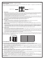
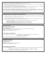
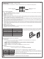
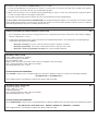
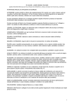
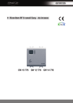
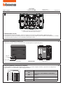
L4572SB
L/N/NT4575SB
PART. U0464C
Istruzioni d’uso
Instructions for use
07/07-01 PC
1
I
L4572SB
Per l’utilizzo con placche Living International staccare
le parti laterali evidenziate in grigio nella figura
COMANDO RADIO L4572SB
Questo dispositivo permette di pilotare, attraverso l’interfaccia ricevente art. L/N/NT4575SB, l’impianto My Home.
Il comando non necessita di scatola da incasso in quanto può essere installato a parete mediante nastro biadesivo (a corredo) o
con normali tasselli ad espansione, non richiedendo quindi opere murarie.
2
INTERFACCIA RICEVENTE L/N/NT4575SB
L’interfaccia ricevente consente al comando radio L4572SB di pilotare l’impianto My Home.
Indicatore
luminoso,
LED
Pulsante a spillo
Vista frontale
L/N/NT4575SB
Vista posteriore
CONFIGURAZIONE DELL’INTERFACCIA RICEVENTE
3
Per poter utilizzare comando radio ed interfaccia ricevente, è necessario eseguire, anzitutto, le operazioni di configurazione
di quest’ultima e, successivamente, quelle di programmazione.
A
A
PL1
M1
PL2
M2
SPE
ambiente
PL1
punto luce 1
(punto fonico 1 solo per diffusione sonora SPE=8)
M1
modalità 1
PL2
punto luce 2
M2
modalità 2
SPE
speciale
4
MODALITÀ AUTOAPPRENDENTE - Configuratore SPE=0
CONFIGURAZIONE
Questa modalità di funzionamento permette di associare ad ogni coppia di tasti, coppia 1-3 e coppia 2-4 del comando radio
L4572SB, una funzione tra quelle descritte di seguito.
1
2
Coppia di tasti 1-3
Coppia di tasti 2-4
3
a)
b)
c)
d)
4
Automazione
- ON/OFF attuatore; funzionamento in modalità O/I. Per pressione breve ON/OFF attuatore, per pressione prolungata regolazione
dimmer (solo per comando punto punto). Al tasto superiore della coppia viene automaticamente associato il comando di ON e
regolazione intensità SU mentre al tasto inferiore viene associato il comando di OFF e regolazione intensità GIÙ.
- ON temporizzato. Entrambi i tasti della coppia eseguono la stessa funzione.
- Lampeggio. Entrambi i tasti della coppia eseguono la stessa funzione.
- SU e GIÙ tapparelle; funzionamento salita-discesa fino a fine corsa in modalità bistabile. Al tasto superiore della coppia viene
automaticamente associato il comando di SU (SU per pressione prolungata, STOP per pressione breve) mentre al tasto inferiore
viene associato il comando di GIÙ (GIÙ per pressione prolungata, STOP per pressione breve).
- Blocca/Sblocca attuatore. Entrambi i tasti della coppia eseguono la stessa funzione.
- Richiamo scenario. Entrambi i tasti della coppia eseguono la stessa funzione.
Videocitofonia
- Comando serratura (anche con conversazione in corso). Entrambi i tasti della coppia eseguono la stessa funzione.
- Comando luci scale. Entrambi i tasti della coppia eseguono la stessa funzione.
- Chiamata al piano (anche generale). Entrambi i tasti della coppia eseguono la stessa funzione.
- Autoaccensione e ciclamento telecamere (solo con modulatore SCS art. F442). Entrambi i tasti della coppia eseguono la stessa funzione.
Diffusione sonora
- ON/OFF amplificatore; l’ON funziona sempre in modalità Follow-me. Per pressione breve ON/OFF amplificatore, per pressione
prolungata regolazione volume. Al tasto superiore della coppia viene automaticamente associato il comando di ON amplificatore
e regolazione volume SU mentre al tasto inferiore viene associato il comando di OFF amplificatore e regolazione volume GIÙ.
- Cicla sorgente/Cambio stazione-brano. Al tasto superiore della coppia viene automaticamente associato il comando di Cicla
sorgente mentre al tasto inferiore viene associato il comando di Cambio stazione radio o brano musicale.
Canali ausuliari
- ON/OFF ausiliario luci; funzionamento in modalità O/I. Al tasto superiore della coppia viene automaticamente associato il comando
di ON mentre al tasto inferiore viene associato il comando di OFF.
- SU e GIÙ tapparelle; funzionamento salita-discesa fino a fine corsa in modalità bistabile. Al tasto superiore della coppia viene
automaticamente associato il comando di SU (SU per pressione prolungata, STOP per pressione breve) mentre al tasto inferiore
viene associato il comando di GIÙ (GIÙ per pressione prolungata, STOP per pressione breve).
- Reset. Entrambi i tasti della coppia eseguono la stessa funzione.
È possibile associare ad ogni singola interfaccia ricevente fino ad un massimo di 24 funzioni (quindi ad ogni interfaccia possono
essere associati fino a 12 comandi radio L4572SB). L’associazione tra la funzione desiderata e la coppia di tasti viene effettuata
attraverso la procedura di seguito descritta.
A
PL1
M1
PL2
M2
SPE
A
0÷9
PL1
1÷9
M1
0
PL2
0
M2
0
SPE
0
PROGRAMMAZIONE
Per associare a ciascuna coppia di tasti del comando radio una funzione, la procedura è la seguente:
1) Premere il pulsante a spillo dell’interfaccia per almeno 3 secondi: il LED rosso si accende fisso. Rilasciare il tasto.
2) Entro 20 secondi premere un tasto della coppia che si vuole programmare sul comando radio; il LED rosso inizierà a lampeggiare
indicando l’attivazione della modalità di programmazione.
3) Entro 5 minuti impostare la funzione che si vuole associare alla coppia di tasti del comando radio, agendo sul dispositivo
corrispondente (es. comando, amplificatore, touch screen, ecc...); il LED rosso lampeggia velocemente per circa 2 secondi per
indicare l’avvenuta associazione.
4) Ripetere i punti 1, 2 e 3 per tutte le coppie di tasti da associare, anche per una coppia per cui l’associazione è già stata effettuata
(nel caso in cui si voglia cambiarla).
Per annullare la programmazione di una coppia di tasti del comando la procedura è la seguente:
1) Premere il pulsante a spillo sull’interfaccia per almeno 8 secondi; dopo 3 secondi il LED rosso si accende fisso, dopo altri 5
secondi si spegne. Rilasciare il tasto. Il LED rosso si riaccende fisso.
2) Entro 20 secondi premere sul comando un tasto della coppia di cui si vuole cancellare la programmazione; il LED rosso lampeggia
velocemente per circa 2 secondi, confermando l’avvenuta cancellazione.
3) Da questo momento la coppia di tasti non attiva più nessun comando finché non viene riprogrammata.
Per cancellare contemporaneamente tutte le associazioni dell’interfaccia, premere il pulsante a spillo sull’interfaccia per
12 secondi circa; dopo 3 secondi il LED rosso si accende fisso, dopo altri 5 secondi si spegne e dopo altri 4 secondi lampeggia
velocemente per circa 2 secondi, confermando l’avvenuta cancellazione di tutte le programmazioni.
Rilasciare il tasto.
5
MODALITÀ STANDARD AUTOMAZIONE - Configuratore SPE=1
CONFIGURAZIONE
Questa modalità di funzionamento permette di implementare le funzioni standard di automazione (ad esempio controllo di luci e
tapparelle).
1
2
La modalità M2 si riferisce
alla coppia di tasti 2-4
La modalità M1 si riferisce
alla coppia di tasti 1-3
3
4
Configurazioni modalità (MI, M2):
a) M= — (nessun configuratore): funzionamento in modalità ciclica ON/OFF attuatore. Per pressione breve ON/OFF attuatore,
per pressione prolungata regolazione dimmer (solo per comando punto punto)*.
b) M=ON: solo comando di ON*.
c) M=OFF: solo comando di OFF*.
d) M= O/I: per pressione breve ON/OFF attuatore, per pressione prolungata regolazione dimmer (solo per comando punto punto).
Al tasto superiore della coppia viene automaticamente associato il comando di ON e regolazione intensità SU mentre al tasto
inferiore viene associato il comando di OFF e regolazione intensità GIÙ.
e) M=⇑⇓: SU e GIÙ tapparelle; funzionamento salita-discesa fino a fine corsa in modalità bistabile. Al tasto superiore della coppia
viene automaticamente associato il comando di SU (SU per pressione prolungata, STOP per pressione breve) mentre al tasto
inferiore viene associato il comando di GIÙ (GIÙ per pressione prolungata, STOP per pressione breve).
f) M=⇑⇓M: SU e GIÙ tapparelle; funzionamento salita-discesa per il tempo di pressione del tasto (massimo 20 secondi) in modalità
monostabile. Al tasto superiore della coppia viene automaticamente associato il comando di SU mentre al tasto inferiore viene
associato il comando di GIÙ. Al rilascio del tasto viene inviato un comando di stop.
g) M=PUL: modalità pulsante*.
h) M=1÷8: temporizzazione (comando ON temporizzato).
La durata della temporizzazione dipende dal valore del configuratore in base alla tabella di seguito riportata *:
i) M= CEN: comando per il programmatore scenari.
Configuratore
1
2
3
4
5
6
7
8
Durata nominale
1 min
2 min
3 min
4 min
5 min
15min
30s
0.5s
* Per le modalità ai punti a) b) c) g) ed h) è necessario montare
sul retro del copritasto l’apposito spessore fornito a corredo,
in modo da utilizzare solo il tasto inferiore della coppia (vedi
figura a lato).
Configurazione Ambiente (A) e Punti Luce (PL1, PL2):
Per modalità dalla a) alla h):
- A=1÷9: è l’ambiente del destinatario del comando per comando punto-punto; PL1, PL2=1÷9 sono i punti luce a cui sono
destinati i comandi
- A=AMB: per comandi di ambiente; PL1, PL2=1÷9 sono gli ambienti a cui sono destinati i comandi
- A=GR: per comandi di gruppo; PL1, PL2=1÷9 sono i gruppi a cui sono destinati i comandi
- A=GEN: per comandi di tipo generale; PL1, PL2 devono essere 0
- A=AUX: per comandi di tipo ausiliario; PL1, PL2=1÷9 mentre M1, M2 devono essere diversi da 1÷8
Per modalità i):
- A=1÷9 e PL1=1÷9: definiscono l’indirizzo locale del comando .
Gli altri configuratori vanno posti a M1=CEN, PL2=0, M2=CEN
Esempio di configurazione:
A
PL1
M1
PL2
M2
SPE
4
1
O/I
3
⇑⇓
1
Con la configurazione a fianco si realizzano le seguenti funzioni:
- la coppia di tasti 1-3 è configurata con ON/OFF luci in modalità O/I. Il tasto 1 esegue
l’ON e regolazione intensità SU mentre il tasto 3 esegue OFF e regolazione intensità
GIÙ dell’attuatore con indirizzo 41;
- la coppia di tasti 2-4 è configurata con SU/GIÙ tapparelle in modalità bistabile. Il tasto
2 esegue il SU mentre il tasto 4 esegue il GIÙ dell’attuatore con indirizzo 43.
Se le posizioni PL2 e M2 non sono configurate, la coppia di tasti 2/4 è disabilitata.
PROGRAMMAZIONE
Per associare un comando radio art. L4572SB all’interfaccia L/N/NT4575SB, la procedura è la seguente:
1) Premere il pulsante a spillo sull’interfaccia per almeno 3 secondi: il LED rosso si accende fisso; rilasciare il tasto.
2) Entro 20 secondi premere, sul comando radio, un tasto della coppia che si vuole programmare; il LED rosso lampeggia velocemente
per circa 2 secondi per indicare l’avvenuta programmazione.
3) A questo punto si possono ripetere i punti 1 e 2 per tutti i codici da memorizzare all’interno dell’interfaccia, fino ad un massimo di 128.
Per eliminare un codice dall’interfaccia L/N/NT4575SB, la procedura è la seguente:
1) Premere il pulsante a spillo sull’interfaccia per almeno 8 secondi (dopo 3 secondi il LED rosso si accende fisso, dopo altri 5
secondi si spegne). Rilasciare il tasto. Il LED rosso si riaccende.
2) Entro 20 secondi premere, sul comando radio, un tasto della coppia di cui si vuole cancellare la programmazione; il LED rosso
lampeggia velocemente per circa 2 secondi, confermando l’avvenuta cancellazione.
3) Da questo momento la coppia di tasti non attiva più nessun comando, finché non viene riprogrammata.
Per cancellare tutte le programmazioni dall’interfaccia L/N/NT4575SB, premere il pulsante a spillo sull’interfaccia per 12 secondi
circa (dopo 3 secondi il LED rosso si accende fisso, dopo altri 5 secondi si spegne e dopo altri 4 secondi lampeggia velocemente
per circa 2 secondi, confermando l’avvenuta cancellazione di tutte le programmazioni). Rilasciare il tasto.
6
MODALITÀ SCENARI REMOTI - Configuratore SPE=6
CONFIGURAZIONE
Questa modalità di funzionamento è possibile solo se nell’impianto è presente un modulo scenari art. F420.
La configurazione in A e PL1 dell’interfaccia deve corrispondere a quella del modulo scenari da comandare.
La configurazione in M1 determina la corrispondenza tra i tasti del comando radio e gli scenari memorizzati nel modulo scenari,
secondo la tabella riportata di seguito.
A
PL1
M1
PL2
M2
SPE
Numero scenario
modulo scenari
Scenario 1
Scenario 2
Scenario 3
Scenario 4
Scenario 5
Scenario 6
Scenario 7
Scenario 8
Scenario 9
Scenario 10
Scenario 11
Scenario 12
Scenario 13
Scenario 14
Scenario 15
Scenario 16
Configuratore
M1=1
Tasto1
Tasto2
Tasto3
Tasto4
Configuratore
M1=2
Configuratore
M1=3
A
0÷9
PL1
1÷9
M1
1÷4
PL2
0
M2
0
SPE
6
Configuratore
M1=4
Disposizione
dei tasti del
comando
L4572SB
1
2
3
4
Modulo scenari
F420
Tasto1
Tasto2
Tasto3
Tasto4
Tasto
autoapprendimento
Tasto1
Tasto2
Tasto3
Tasto4
��������
���
Tasto1
Tasto2
Tasto3
Tasto4
LED Verde
Dopo aver configurato l’interfaccia, i quattro scenari associati al comando L4572SB possono essere richiamati anche da altri comandi
dello stesso tipo (fino ad un massimo di 128 comandi).
PROGRAMMAZIONE
Per programmare uno scenario, la procedura è la seguente:
1) Il modulo scenari deve essere in configurazione con autoapprendimento abilitato (premere il tasto di autoapprendimento sul
modulo scenari in modo che il relativo LED sia verde).
2) Premere il pulsante a spillo dell’interfaccia L/N/NT4575SB per almeno 3 secondi: il LED rosso si accende fisso. Rilasciare il tasto.
3) Premere entro 20 secondi sul comando radio il tasto relativo allo scenario che si vuole programmare: il LED rosso inizierà a
lampeggiare, indicando l’attivazione della modalità di programmazione.
4) Impostare lo scenario, agendo sui dispositivi corrispondenti dell’impianto My Home (es. comando, amplificatore, touch screen, ecc...)
5) Entro 35 minuti premere il tasto a spillo sull’interfaccia per uscire dalla programmazione: il LED rosso si spegne.
6) Ripetere i punti da 2 a 5 per tutti gli scenari che si vogliono programmare.
7) Se si vuole disabilitare la possibilità di programmazione o cancellazione degli scenari, premere il tasto di autoapprendimento del
modulo scenari in modo che il LED relativo sia rosso.
Per cancellare uno scenario, la procedura è la seguente:
1) Il modulo scenari deve essere in configurazione con autoapprendimento abilitato.
2) Premere il pulsante a spillo sull’interfaccia per almeno 8 secondi (dopo 3 secondi il LED rosso si accende fisso, dopo altri 5
secondi torna a spegnersi). Rilasciare il tasto. Il LED rosso si riaccende.
3) Premere entro 20 secondi sul comando radio il tasto relativo allo scenario che si vuole cancellare; quando il modulo scenari invia
conferma dell’avvenuta cancellazione, il LED rosso lampeggia velocemente per circa 2 secondi e successivamente si spegne.
4) Ripetere i punti da 2 e 3 per tutti gli scenari che si vogliono cancellare.
Per cancellare contemporaneamente tutte le programmazioni dell’interfaccia, premere il pulsante a spillo sull’interfaccia per
12 secondi circa (dopo 3 secondi il LED rosso si accende fisso, dopo altri 5 secondi si spegne e dopo altri 4 secondi lampeggia
velocemente per circa 2 secondi, confermando la cancellazione). Rilasciare il tasto.
Nota: con questa operazione non vengono cancellati gli scenari contenuti nel modulo scenari.
Cancellazione di tutti gli scenari: per fare questa operazione occorre tener premuto per 10 secondi il tasto DEL direttamente sul
modulo scenari, dopo aver premuto il tasto di autoapprendimento in modo che il LED di autoapprendimento sia verde.
MODALITÀ DIFFUSIONE SONORA - Configuratore SPE=8
CONFIGURAZIONE
Questa modalità di funzionamento permette di implementare le funzioni della diffusione sonora.
7
In questa modalità operativa, i tasti del comando radio funzionano come indicato di seguito:
Tasto 1 La pressione breve attiva la sorgente
e l’amplificatore.
La pressione prolungata aumenta il volume.
Tasto 3 La pressione breve spegne l’amplificatore.
La pressione prolungata diminuisce il volume.
1
2
Tasto 2 Cambia sorgente sonora.
3
4
Tasto 4 Cambia brano o stazione radio.
Configurazione Ambiente (A) e Punto Fonico (PL1):
–
–
–
A=0÷9: è l’ambiente dell’amplificatore; PL1=0÷9: è il punto fonico dell’amplificatore;
A=AMB: per comandi di ambiente; PL1=0÷9: è l’ambiente a cui è destinato il comando;
A=GEN: per comandi di tipo generale; PL1 deve essere 0.
Configurazione Modalità (M1):
–
M1=0÷9: sorgente da accendere prima di accendere l’amplificatore; se M=0 viene accesa la sorgente 1 senza prima effettuare
l’OFF delle sorgenti (in modalità Follow-me).
I configuratori PL2 e M2 devono essere 0.
PROGRAMMAZIONE
Per associare un comando radio art. L4572SB all’interfaccia L/N/NT4575SB, la procedura è la seguente:
1) Premere il pulsante a spillo sull’interfaccia per almeno 3 secondi: il LED rosso si accende fisso; rilasciare il tasto.
2) Entro 20 secondi premere il tasto sul comando radio che si vuole programmare; il LED rosso lampeggia velocemente per circa
2 secondi per indicare l’avvenuta programmazione.
3) A questo punto si possono ripetere i punti 1 e 2 per tutti i codici da memorizzare all’interno dell’interfaccia, fino ad un massimo
di 128.
Per eliminare un codice dall’interfaccia L/N/NT4575SB, la procedura è la seguente:
1) Premere il pulsante a spillo sull’interfaccia per almeno 8 secondi (dopo 3 secondi il LED rosso si accende fisso, dopo altri 5
secondi si spegne). Rilasciare il tasto. Il LED rosso si riaccende.
2) Entro 20 secondi premere sul comando uno dei quattro tasti che si vuole cancellare; il LED rosso lampeggia velocemente per 2
secondi, confermando l’avvenuta cancellazione.
3) Da questo momento il comando è cancellato, finché non viene riprogrammato.
Per cancellare tutti i codici dall’interfaccia L/N/NT4575SB, premere il pulsante a spillo sull’interfaccia per 12 secondi circa (dopo
3 secondi il LED rosso si accende fisso, dopo altri 5 secondi si spegne e dopo altri 4 secondi lampeggia velocemente per circa 2
secondi, confermando l’avvenuta cancellazione di tutte le programmazioni). Rilasciare il tasto.
8
MODALITÀ VIDEOCITOFONIA - Configuratore SPE=9
CONFIGURAZIONE
Questa modalità di funzionamento permette di interagire con l’impianto di videocitofonia assegnando al comando radio alcune
funzioni quali: accensione luci scale, chiamata al piano e apertura serratura del posto esterno.
Configurazione Modalità (M1,M2):
I configuratori di modalità M1 (coppia di tasti 1-3) ed M2 (coppia di tasti 2-4) devono essere configurati in uno dei seguenti modi:
–
M=1: comando doppio per apertura serratura
A e PL1 (se M1=1 e M2≠0) sono l’indirizzo del posto esterno di cui comandare la serratura: il tasto 3 comanda la serratura
del posto esterno (A/PL1) mentre il tasto 1 comanda la serratura del posto esterno (A/PL1)+1.
A e PL2 (se M2=1) sono l’indirizzo del posto esterno di cui comandare la serratura: il tasto 4 comanda la serratura del posto
esterno (A/PL2) mentre il tasto 2 comanda la serratura del posto esterno (A/PL2)+1.
L’indirizzo del posto esterno specificato in A/PL1 o in A/PL2 deve essere minore o uguale a 95.
–
M=2: comando per chiamata al piano
A e PL1 (se M1=2) e/o A e PL2 (se M2=2) sono l’indirizzo (due cifre) del posto interno da chiamare.
–
M=3: comando per accensione luci scale
A e PL1 (se M1=3) oppure A e PL2 (se M2=3) sono l’indirizzo (due cifre) corrispondente al posto interno da cui si comandano
le luci scale.
Esempio di configurazione:
Configurazione interfaccia
L/N/NT4575SB
A
2
PL1
1
M1
1
PL2
6
M2
3
SPE
9
Comando radio L4572SB
Posto esterno 22
Luci scale 26
1
2
Posto esterno 21
Luci scale 26
3
4
In generale se PL2 e M2 non sono configurati, i tasti di destra (2 e 4) sono disabilitati. Fa eccezione il solo caso con:
– M1=1, M2=0, PL2=0: comando quadruplo per apertura serratura
A e PL1 sono l’indirizzo (due cifre) del posto esterno di cui comandare la serratura: il tasto 3 comanda la serratura del posto
esterno (A/PL1), il tasto 4 comanda la serratura del posto esterno (A/PL1)+1, il tasto 1 quella del posto esterno (A/PL1)+2
ed il tasto 2 quella del posto esterno (A/PL1)+3. L’indirizzo del posto esterno specificato in A/PL1 deve essere minore o
uguale a 95.
Configurazione interfaccia
L/N/NT4575SB
A
1
PL1
3
M1
1
PL2
0
M2
0
SPE
9
Comando radio L4572SB
Posto esterno 15
Posto esterno 16
1
2
Posto esterno 13
Posto esterno 14
3
4
PROGRAMMAZIONE
Per associare un dispositivo radio all’interfaccia L/N/NT4575SB, la procedura è la seguente:
1) Premere il pulsante a spillo sull’interfaccia per almeno 3 secondi: il LED rosso si accende fisso; rilasciare il tasto.
2) Entro 20 secondi premere un tasto, della coppia che si vuole programmare, sul comando radio; il LED rosso lampeggia velocemente
per circa 2 secondi per indicare l’avvenuta programmazione.
3) A questo punto si possono ripetere i punti 1 e 2 per tutti i codici da memorizzare all’interno dell’interfaccia, fino ad un massimo
di 128.
Per eliminare un codice dall’interfaccia L/N/NT4575SB, la procedura è la seguente:
1) Premere il pulsante a spillo sull’interfaccia per almeno 8 secondi (dopo 3 secondi il LED rosso si accende fisso, dopo altri 5
secondi si spegne). Rilasciare il tasto. Il LED rosso si riaccende.
2) Entro 20 secondi premere sul comando un tasto della coppia di cui si vuole cancellare la programmazione; il LED rosso lampeggia
velocemente per circa 2 secondi, confermando l’avvenuta cancellazione.
3) Da questo momento la coppia di tasti non invia più nessun comando, finché non viene riprogrammata.
Per cancellare tutti i codici dall’interfaccia L/N/NT4575SB, premere il pulsante a spillo sull’interfaccia per 12 secondi circa (dopo
3 secondi il LED rosso si accende fisso, dopo altri 5 secondi si spegne e dopo altri 4 secondi lampeggia velocemente per circa 2
secondi, confermando l’avvenuta cancellazione di tutte le programmazioni). Rilasciare il tasto.
9
AVVERTENZE GENERALI SULL’INTERFACCIA RADIO L/N/NT4575SB:
1)
Se la configurazione inserita nell’interfaccia è errata (o non ci sono i configuratori), il LED dell’interfaccia inizia a lampeggiare
senza mai fermarsi, fino a che la configurazione viene corretta.
2)
Se, durante il tentativo di programmazione/cancellazione di un comando radio all’interfaccia L/N/NT4575SB, il LED rosso si
spegne senza dare alcuna conferma, si è verificato uno dei seguenti eventi:
–
durante la cancellazione: il codice non è presente in memoria e quindi non può essere cancellato;
–
durante la programmazione: la memoria è piena e quindi non accetta più codici;
–
durante la programmazione/cancellazione scenari: il modulo scenari è bloccato.
DATI TECNICI L4572SB
Alimentazione: Generatore piezoelettrico
Frequenza di trasmissione: 868 MHz
Tipo di modulazione: ASK
Portata: 70 metri in area libera (pareti in metallo e cemento o placche metalliche riducono la portata)
Ingombro: 2 moduli Living International, Light, Light Tech
Temperatura di funzionamento: 0°C ÷ +40°C
10
DICHIARAZIONE CE DI CONFORMITÀ
L’articolo: L4572SB è conforme ai requisiti essenziali della direttiva 1999/5/CE, in quanto rispetta le seguenti norme:
ETSI EN 300 220-3 ETSI EN301 489-3
Anno di approvazione della marcatura CE secondo la direttiva indicata: 2005
DATI TECNICI L/N/NT4575SB
Assorbimento massimo: 33 mA
Alimentazione: 18 ÷ 27 Vdc
Frequenza: 868 MHz
Ingombro: 2 moduli Living International, Light, Light Tech
Temperatura di funzionamento: 0°C ÷ +40°C
11
DICHIARAZIONE CE DI CONFORMITÀ
Gli articoli: L/N/NT4575SB sono conformi ai requisiti essenziali della direttiva 1999/5/CE, in quanto rispettano le seguenti norme:
ETSI EN 300 220-3 ETSI EN301 489-3 EN60950 EN50090-2-2 EN50090-2-3 EN50428
Anno di approvazione della marcatura CE secondo la direttiva indicata: 2005
12
GB
L4572SB
For use with Living International cover plates,
remove the side parts shown in grey in the figure
RADIO CONTROL L4572SB
By means of the receiving interface item L/N/NT4575SB, this device can control the My Home system.
The control does not need a flush-mounted box because it can be installed on the wall using two-sided adhesive tape (supplied),
thus not requiring making holes in the wall, or with normal rawlplugs.
13
RECEIVING INTERFACE L/N/NT457SB
The radio interface lets the radio control L4572SB control the My Home system.
Luminous
indicator,
LED
Pin pushbutton
L/N/NT4575SB
Front view
Rear view
CONFIGURATION OF THE RECEIVING INTERFACE
14
To use the radio control and receiving interface the interface must first be configured and then programmed.
A
A
PL1
M1
PL2
M2
SPE
room
PL1
light point 1
(sound point 1 only for sound system SPE=8)
M1
mode 1
PL2
light point 2
M2
mode 2
SPE
special
15
SELF-LEARNING MODE - Configurator SPE=0
CONFIGURATION
This mode of operation can associate a function from those described below with each pair of keys, pair 1-3 and pair 2-4, of radio
control L4572SB.
1
2
Pair of keys 1-3
Pair of keys 2-4
3
a)
b)
c)
d)
4
Automation
- Actuator ON/OFF; operation in O/I mode. With quick press actuator ON/OFF, with long press dimmer adjustment (only for
point point command). The ON command and intensity adjustment UP are automatically associated with the upper key of the
pair while the OFF command and intensity adjustment DOWN are associated with the lower key.
- Timed ON. Both keys of the pair perform the same function.
- Flash. Both keys of the pair perform the same function.
- Rolling shutters UP and DOWN; up-down operation to limit switch in bistable mode. The UP command (UP for long press,
STOP for short press) is automatically associated with the upper key of the pair while the DOWN command (DOWN for long
press, STOP for short press) is associated with the lower key.
- Lock/unlock actuator. Both keys of the pair perform the same function.
- Call scenario. Both keys of the pair perform the same function.
Video door entry
- Control door lock (also with call in progress). Both keys of the pair perform the same function.
- Control staircase lights. Both keys of the pair perform the same function.
- Floor call (all calls). Both keys of the pair execute the same function.
- Auto-Switching On and cycle mode of cameras (only with SCS modulator item F442). Both keys of the pair execute the same function.
Sound system
- Amplifier ON/OFF; the ON always works in Follow me mode. With quick press amplifier ON/OFF, with long press volume
adjustment. The amplifier ON and volume UP commands are automatically associated with the upper key of the pair while the
amplifier OFF and volume DOWN commands are associated with the lower key.
- Cycle source/Change station-tune. The Cycle source command is automatically associated with the upper key of the pair while
the Radio station or track change command is associated with the lower key.
Auxiliary channels
- Auxiliary lights ON/OFF; operation in O/I mode. The ON command is automatically associated with the upper key of the pair
while the OFF command is associated with the lower key.
- Rolling shutters UP and DOWN; up-down operation to limit switch in bistable mode. The UP command (UP for long press,
STOP for short press) is automatically associated with the upper key of the pair while the DOWN command (DOWN for long
press, STOP for short press) is associated with the lower key.
- Reset. Both keys of the pair perform the same function.
Up to 24 functions can be associated with each receiving interface (i.e. up to 12 radio controls L4572SB can be associated with
each interface). The function required and the key pair are associated by means of the procedure described below.
A
PL1
M1
PL2
M2
SPE
A
0-9
PL1
1-9
M1
0
PL2
0
M2
0
SPE
0
PROGRAMMING
To associate a function with each of the radio control pairs of keys, proceed as follows:
1) Press the pin pushbutton on the interface for at least 3 seconds; the red LED shines steadily. Release the key.
2) Within 20 seconds press one key of the pair on the radio control which you want to program; the red LED starts to flash indicating
that the programming mode is activated.
3) Within 5 minutes set the function to be associated with the pair of keys of the remote control by means of the corresponding device
(ex. command, amplifier, touch screen, etc.); the red LED flashes quickly for about 2 seconds to indicate that the programming
has taken place.
4) Points 1, 2 and 3 can be repeated for all the pairs of keys, even for a pair for which the association has already been made (if
you want to change it).
To cancel the programming of a pair of keys proceed as follows:
1) Press the pin pushbutton for at least 8 seconds; after 3 seconds the red LED shines steadily, after another 5 seconds it goes
out. Release the key. The red LED shines steadily.
2) Within 20 seconds press on the control one key of the pair whose programming is to be cancelled; the red LED flashes quickly
for about 2 seconds to indicate that the cancelling has taken place.
3) From this moment the pair of keys will not activate any commands until it has been reprogrammed.
To cancel all the interface associations at the same time, press the pin pushbutton on the interface for about 12 seconds; after
3 seconds the red LED shines steadily, after another 5 seconds it goes out and after another 4 seconds it flashes quickly for about
2 seconds, confirming that all the programming have been cancelled.
Release the key.
16
STANDARD AUTOMATION MODE - Configurator SPE=1
CONFIGURATION
This mode of operation can implement the standard automation functions (e.g. control lights and rolling shutters).
1
2
Mode M1 refers to pair
of keys 2-4
Mode M1 refers to pair
of keys 1-3
3
4
Mode configurations (M1, M2):
a) M= — (no configurator): operation in cyclical mode actuator ON/OFF. With quick press actuator ON/OFF, with long press
dimmer adjustment (only for point point command)*.
b) M=ON: only ON command*.
c) M=OFF: only OFF command*.
d) M= O/I: with quick press actuator ON/OFF, with long press dimmer adjustment (only for point point command). The ON and
intensity adjustment UP commands are automatically associated with the upper key of the pair while the OFF and intensity
adjustment DOWN commands are associated with the lower key.
e) M=⇑⇓: rolling shutters UP and DOWN; up-down operation to limit switch in bistable mode. The UP command (UP for long press,
STOP for short press) is automatically associated with the upper key of the pair while the DOWN command (DOWN for long
press, STOP for short press) is associated with the lower key.
f) M=⇑⇓M: rolling shutters UP and DOWN; up-down operation for the time the key is pressed (maximum 20 seconds) in monostable
mode. The UP command (UP for long press, STOP for short press) is automatically associated with the upper key of the pair
while the DOWN command (DOWN for long press, STOP for short press) is associated with the lower key. Releasing the key
sends a stop command.
g) M=PUL: pushbutton mode*.
h) M=1-8: timing (ON command timed).
The duration of the timing depends on the configurator value on the basis of the following table*:
i) M= CEN: command for the scenario programmer.
Configurator
1
2
3
4
5
6
7
8
Nominal duration
1 min
2 min
3 min
4 min
5 min
15min
30s
0.5s
* For the modes in points a) b) c) g) and h) the spacer supplied
must be mounted on the back of the key cover, so that only
the lower key of the pair is used (see figure to the side).
Room (A) and Light Point (PL1, PL2) configuration:
For mode a) to h):
- A=1-9: is the room of the command recipient for point-point command: PL1, PL2=1-9 are the light points
for which the commands are intended
- A=AMB: for room commands; PL1, PL2=1-9 are the rooms for which the commands are intended
- A=GR: for group commands; PL1, PL2=1-9 are the groups for which the commands are intended
- A=GEN: for general commands; PL1, PL2 must be 0
- A=AUX: for auxiliary commands; PL2=1-9 while M1, M2 must be different from 1-8
For mode i):
- A=1-9 and PL1=1-9: determine the local address of the command.
The other configurators must be set to M1=CEN, PL2=0, M2=CEN
Example of configuration:
A
PL1
M1
PL2
M2
SPE
4
1
O/I
3
⇑⇓
1
The following functions are obtained with the configuration to the side:
- the pair of keys 1-3 is configured with lights ON/OFF in O/I mode. Key 1 performs the
ON and the intensity adjustment UP while key 3 performs OFF and intensity adjustment
DOWN of the actuator with address 41;
- the pair of keys 2-4 is configured with rolling shutters UP/DOWN in bistable mode. Key 2
performs the UP while key 4 performs OFF and DOWN of the actuator with address 43.
If positions PL2 and M2 are not configured, the pair of keys 2/4 is disabled.
PROGRAMMING
To associate a radio control item L4572SB to interface L/N/NT4575SB, proceed as follows:
1) Press the pin pushbutton on the interface for at least 3 seconds; the red LED shines steadily. Release the key.
2) Within 20 seconds press a key of the pair on the radio control which you want to program; the red LED flashes quickly indicating
that the programming has taken place.
3) At this point points 1 and 2 can be repeated for all the codes to be saved inside the interface, up to a maximum of 128.
To cancel a code from interface L/N/NT4575SB, proceed as follows:
1) Press the pin pushbutton on the interface for at least 8 seconds (after 3 seconds the red LED shines steadily, after another 5
seconds it goes out). Release the key. The red LED lights up again.
2) Within 20 seconds press a key of the pair on the radio control whose programming is to be cancelled; the red LED flashes quickly
for about 2 seconds to indicate that the cancelling has taken place.
3) From this moment the pair of keys will not activate any commands until it has been reprogrammed.
To cancel all the programming of interface L/N/NT4575SB, press the pin pushbutton for about 12 seconds (after 3 seconds the
red LED shines steadily, after another 5 seconds it goes out and after another 4 seconds it flashes quickly for about 2 seconds,
confirming that all the programmings have been cancelled). Release the key.
17
REMOTE SCENARIO MODE - Configurator SPE=6
CONFIGURATION
This mode of operation is only possible if the system has a scenario module item F420.
The configuration in A and PL1 of the interface must correspond to that of the scenario module to be controlled.
The configuration in M1 determines the correspondence between the keys of the radio remote control and the scenarios saved in
the scenario module, according to the table given below.
A
PL1
M1
PL2
M2
SPE
Scenario number
scenario module
Scenario 1
Scenario 2
Scenario 3
Scenario 4
Scenario 5
Scenario 6
Scenario 7
Scenario 8
Scenario 9
Scenario 10
Scenario 11
Scenario 12
Scenario 13
Scenario 14
Scenario 15
Scenario 16
Configurator
M1=1
Key 1
Key 2
Key 3
Key 4
Configurator
M1=2
Configurator
M1=3
A
0-9
PL1
1-9
M1
1-4
PL2
0
M2
0
SPE
6
Configurator
M1=4
Layout of the
keys of control
L4572SB
1
2
3
4
Scenario
module F420
Key 1
Key 2
Key 3
Key 4
Self-learning key
Key 1
Key 2
Key 3
Key 4
��������
���
Key 1
Key 2
Key 3
Key 4
Green LED
After configuring the interface the four scenarios associated with remote control L4572SB can also be called by other remote controls
of the same type (up to a maximum of 128 commands).
PROGRAMMING
To program a scenario, proceed as follows:
1) The scenario module must be in configuration with self-learning enabled (press the self-learning key so that its LED is green).
2) Press the pin pushbutton of interface L/N/NT4575SB for at least 3 seconds: the red LED shines steadily. Release the key.
3) Within 20 seconds press the key on the radio remote control for the scenario to be programmed; the red LED starts to flash
indicating that the programming mode is activated.
4) Set the scenario by means of the corresponding devices of the My Home system (ex. command, amplifier, touch screen, etc.)
5) Within 35 minutes press the pin key on the interface to quit the programming; the red LED goes out.
6) Repeat points 2 to 5 for all the scenarios to be programmed.
7) If you want to disable the possibility of programming or cancelling the scenario, press the scenario module self-learning key so
that its LED is red.
To cancel a scenario, proceed as follows:
1) The scenario module must be in configuration with self-learning enabled.
2) Press the pin pushbutton on the interface for at least 8 seconds (after 3 seconds the red LED shines steadily, after another 5
seconds it goes out). Release the key. The red LED lights up again.
3) Within 20 seconds press the key on the remote control for the scenario to be cancelled; when the scenario module sends
confirmation that the cancelling has taken place the red LED flashes quickly for about 2 seconds and then goes out.
4) Repeat points 2 and 3 for all the scenarios to be cancelled.
To cancel all the interface programmings simultaneously, press the pin pushbutton on the interface for about 12 seconds (after
3 seconds the red LED shines steadily, after another 5 seconds it goes out and after another 4 seconds it flashes quickly for about
2 seconds, confirming the cancellation). Release the key.
Note: with this operation the scenarios in the scenario module are not cancelled.
Cancelling all the scenarios: to do this press the self-learning key so that the self-learning LED becomes green then press the DEL
key directly on the scenario module for 10 seconds.
18
SOUND SYSTEM MODE - Configurator SPE=8
CONFIGURATION
This mode of operation implements the sound system functions.
In this mode of operation, the radio control keys work as indicated below:
Key 1
Press quickly to activate the source
and the amplifier.
Press for longer to increase the volume.
Key 3
Press quickly to switch the amplifier OFF.
Press for longer to decrease the volume.
1
2
Key 2
Change sound source.
3
4
Key 4
Change tune or radio station.
Room (A) and Sound Point (PL1) configuration:
–
–
–
A=0-9: is the amplifier room; PL1=0-9: is the amplifier sound point;
A=AMB: for room commands; PL1=0-9: is the room for which the command is intended;
A=GEN: for general commands; PL1 must be 0.
Mode (M1) configuration:
–
M1=0-9: source to be switched on before switching the amplifier on; if M=0 source 1 is switched on without switching the
sources OFF first (in Follow-me mode).
Configurators PL2 and M2 must be 0.
PROGRAMMING
To associate a radio control item L4572SB with interface L/N/NT4575SB, proceed as follows:
1) Press the pin pushbutton on the interface for at least 3 seconds: the red LED shines steadily. Release the key.
2) Within 20 seconds press the key on the radio control which you want to program; the red LED flashes quickly indicating that the
programming has taken place.
3) At this point points 1 and 2 can be repeated for all the codes to be saved inside the interface, up to a maximum of 128.
To cancel a code from interface L/N/NT4575SB, proceed as follows:
1) Press the pin pushbutton on the interface for at least 8 seconds (after 3 seconds the red LED shines steadily, after another 5
seconds it goes out). Release the key. The red LED lights up again.
2) Within 20 seconds press one of the four keys which you want to cancel; the red LED flashes quickly for about 2 seconds to
indicate that the cancelling has taken place.
3) From this moment the command is cancelled until it has been reprogrammed.
To cancel all the codes of interface L/N/NT4575SB, press the pin pushbutton for about 12 seconds (after 3 seconds the red LED
shines steadily, after another 5 seconds it goes out and after another 4 seconds it flashes quickly for about 2 seconds, confirming
that all the programmings have been cancelled). Release the key.
19
VIDEO DOOR ENTRY MODE - Configurator SPE=9
CONFIGURATION
This mode of operation interacts with the video door entry system assigning some functions to the radio control such as: switching
on the staircase lights, call to the floor and opening the door lock from the entrance panel.
Mode (M1, M2) configuration:
The mode configurators M1 (pair of keys 1-3) and M2 (pair of keys 2-4) must be configured in one of the following ways:
–
M=1: double command for door lock opening
A and PL1 (if M1=1 and M2≠0) are the address of the entrance panel which will control the door lock: key 3 controls the
entrance panel door lock (A/PL1) while key 1 controls the entrance panel door lock (A/PL1)+1.
A and PL2 (if M2=1) are the address of the entrance panel which will control the door lock: key 4 controls the entrance panel
door lock (A/PL2) while key 1 controls the entrance panel door lock (A/PL2)+1.
The address of the entrance panel specified in A/PL1 or in A/PL2 must be 95 or less than 95.
–
M=2: command for call to the floor
A and PL1 (if M1=2) and/or A and PL2 (if M2=2) are the address (two digits) of the handset to call.
–
M=3: command to switch on staircase lights
A and PL1 (if M1=3) and/or A and PL2 (if M2=3) are the address (two digits) corresponding to the handset which will control
the staircase lights.
Example of configuration:
Interface L/N/NT4575SB configuration
A
2
PL1
1
M1
1
PL2
6
M2
3
SPE
9
Radio control L4572SB
Staircase lights 26
Entrance panel 22
1
2
Staircase lights 26
Entrance panel 21
3
4
In general if PL2 and M2 are not configured, the right keys (2 and 4) are disabled. The only exception to this is:
– M1=1, M2=0, PL2=0: quadruple command for door lock opening
A and PL1 are the address (two digits) of the entrance panel which will control the door lock: key 3 controls the door lock
of entrance panel (A/PL1), key 4 controls the door lock entrance panel (A/PL1)+1, key 1 controls that of entrance panel
(A/PL1)+2 and key 2 that of entrance panel (A/PL1)+3. The address of the entrance panel specified in A/PL1 must be 95 or
less than 95.
Interface L/N/NT4575SB configuration
A
1
PL1
3
M1
1
PL2
0
M2
0
SPE
9
Radio control L4572SB
Entrance panel 15
Entrance panel 16
1
2
Entrance panel 13
Entrance panel 14
3
4
PROGRAMMING
To associate a radio device to interface L/N/NT4575SB, proceed as follows:
1) Press the pin pushbutton on the interface for at least 3 seconds: the red LED shines steadily. Release the key.
2) Within 20 seconds press a key on the radio control of the pair which you want to program; the red LED flashes quickly indicating
that the programming has taken place.
3) At this point points 1 and 2 can be repeated for all the codes to be saved inside the interface, up to a maximum of 128.
To cancel a code from interface L/N/NT4575SB, proceed as follows:
1) Press the pin pushbutton on the interface for at least 8 seconds (after 3 seconds the red LED shines steadily, after another 5
seconds it goes out). Release the key. The red LED lights up again.
2) Within 20 seconds press a key of the pair whose programming you want to cancel; the red LED flashes quickly for about 2
seconds to indicate that the cancelling has taken place.
3) From this moment the pair of keys will not send any command until it has been reprogrammed.
To cancel all the codes from interface L/N/NT4575SB, press the pin pushbutton for about 12 seconds (after 3 seconds the red LED
shines steadily, after another 5 seconds it goes out and after another 4 seconds it flashes quickly for about 2 seconds, confirming
that all the programmings have been cancelled). Release the key.
GENERAL WARNINGS ON RADIO INTERFACE L/N/NT4575SB
20
1)
If the configuration in the interface is wrong (or there are no configurators) the interface LED starts to flash without stopping,
until the configuration is correct.
2)
If, while trying to program/cancel a radio command in the L/N/NT4575SB interface, the red LED goes out without giving a
confirmation, there are three possibilities:
–
during the cancelling, the code is not in the memory and thus cannot be cancelled;
–
during the programming, the memory is full and thus will not accept any more codes;
–
during the scenario programming/cancelling, the scenario module is blocked.
TECHNICAL DATA L4572SB
Power supply: Piezoelectric generator
Transmission frequency: 868 MHz
Type of modulation: ASK
Range: 70 m in free space (metal and cement walls or metal plates reduce the range)
Size: 2 Living International, Light, Light Tech modules
Operating temperature: 0°C - +40°C
21
CE DECLARATION OF CONFORMITY
Item L4572SB conforms to the essential requirements of directive 1999/5/CE, because it respects the following standards:
ETSI EN 300 220-3 ETSI EN301 489-3
Year of approval of the CE marking according to the directive indicated: 2005
TECHNICAL DATA L/N/NT4575SB
Maximum absorption: 33 mA
Power supply: 18 - 27 Vdc
Frequency: 868 MHz
Size: 2 Living International, Light, Light Tech modules
Operating temperature: 0°C - +40°C
22
CE DECLARATION OF CONFORMITY
Items L/N/NT4575SB conform to the essential requirements of directive 1999/5/CE, because they respect the following standards:
ETSI EN 300 220-3 ETSI EN301 489-3 EN60950 EN50090-2-2 EN50090-2-3 EN50428
Year of approval of the CE marking according to the directive indicated: 2005