1
344163
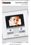
Polyx Memory Display
Manuale installatore • Installation manual
Part. O0192B - 09/10-01 PC
Polyx Memory Display
2
IT
ITALIANO
3
EN
english
25
Indice
1 Introduzione
4
1.1 Avvertenze e consigli
4
1.2 Contenuto della confezione
4
2 Descrizione
5
2.1 Funzioni principali
5
2.2 Vista frontale
6
2.3 Tasti funzioni videocitofoniche 7
2.4 Tasti di navigazione
7
2.5 Tasto funzione Segreteria
7
2.6 Vista posteriore
8
3 Installazione
3.1 Installazione a parete con base metallica a corredo
9
9
4 Configurazione rapida
10
5 Configurazione avanzata
13
5.1 Flessibilità nella composizione
13
5.2 Personalizzazione dei testi
14
5.3 Altre funzionalità
15
5.4 Collegamento al PC
16
6 Impostazioni
6.1 Menù configurazione
17
18
6.1.1 Opzioni
19
6.1.2 Configurazione posto interno
20
6.1.3 Reset
21
7 Come risolvere eventuali inconvenienti
7.1 Modalità push to talk
8 Appendice
22
22
24
3
Manuale Installatore
Polyx Memory Display
1 Introduzione
1.1 Avvertenze e consigli
Prima di procedere con l’installazione è importante leggere attentamente il presente manuale.
La garanzia decade automaticamente per negligenza, uso improprio, manomissione per opera di
personale non autorizzato.
Pertanto Polyx Memory Display:
– deve essere installato solo in ambienti interni;
– non deve essere esposto a stillicidio o a spruzzi d'acqua;
– deve essere usato unicamente su sistemi videocitofonici digitali 2 fili BTicino.
1.2 Contenuto della confezione
La confezione contiene:
• Polyx Memory Display
• Manuale Installatore
• Istruzioni d’uso
• CD
4
2 Descrizione
2.1 Funzioni principali
Polyx Memory Display BTicino rappresenta l'evoluzione del videocitofono che si integra alla gestione dell'impianto domestico. Oltre a tutte le funzioni della videocitofonia digitale 2 fili, in impianti integrati con il sistema My Home Legrand multimedia, Polyx Memory Display permette di
gestire la casa: dalla sicurezza al benessere sino all'intrattenimento (visualizzazione stato allarmi,
diffusione sonora, regolazione temperatura singoli ambienti).
È dotato di schermo LCD a colori da 3,5", menù ad icone, tasti per la navigazione nel menù e tasti
per funzioni di videocitofonia.
INTEGRAZIONI
Comunicazione:
Permette l'accesso, tramite la pagina principale del menù ad un set di funzioni videocitofoniche
predefinite:
INTERCOM – chiamata intercomunicante ad un posto interno
TELECAMERA – attivazione diretta della telecamera associata al posto esterno o scorporata per
videocontrollo
ATTIVAZIONE – attivazione diretta dell'attuatore associato al posto esterno
SELEZIONE CICLICA – attivazione ciclica delle telecamere presenti sull'impianto
SEGRETERIA – permette di registrare dal posto esterno messaggi audio/video in caso di assenza; è
possibile inoltre lasciare dei memo direttamente dal videocitofono.
Scenari:
Consente di attivare i primi cinque scenari memorizzati nel modulo scenari.
Allarmi:
Consente di visualizzare le zone parzializzate, lo stato del sistema e gli ultimi tre allarmi ricevuti
con le relative informazioni (tipo di allarme).
Diffusione sonora:
Consente di gestire la diffusione sonora digitale BTicino; ciclare le sorgenti e il brano/stazione della
sorgente attiva.
Termoregolazione:
Consente di monitorare lo stato della centrale termoregolazione, visualizzare e regolare la temperatura (manuale) nelle singole zone dell'abitazione ed impostare lo stato di Protezione/Settimanale/Off.
5
Manuale Installatore
Polyx Memory Display
2 Descrizione
2.2 Vista frontale
1
12
2
3
11
10
4
9
5
8
7
6
1 - Microfono.
2 - Display LCD a colori; visualizza i menù che guidano le operazioni di utilizzo e programmazione,
mostra le immagini riprese dal posto esterno o da altre telecamere.
3 - Tastiera di navigazione; permette la navigazione all’interno dei menù, la conferma (tasto OK) o l’annullamento (tasto C) delle operazioni di programmazione.
4 - Tasto accensione posto esterno e ciclamento.
5 - Tasto connessione; attiva/disattiva la connessione fonica.
6 - Led connessione.
7 - Altoparlante.
8 - Led serratura.
9 - Tasto serratura; permette l'attivazione dell'elettroserratura del posto esterno associato o connesso.
10 -Led di notifica stato Segreteria.
11 -Tasto Segreteria: attiva/disattiva la funzione Segreteria.
12 -Led esclusione suoneria di chiamata.
6
2.3 Tasti funzioni videocitofoniche
Attivazione Posto Esterno/Ciclamento
Attiva l'accensione del Posto Esterno associato e se presenti, permette il ciclamento degli altri Posti Esterni/telecamere.
Tasto serratura
In connessione apre la serratura del Posto Esterno connesso, a riposo quella del
Posto Esterno associato.
Il led segnala l'avvenuta attivazione.
Tasto connessione
Attiva/disattiva la connessione. Ricevuta una chiamata il led lampeggia, durante la conversazione rimane acceso fisso.
A riposo attiva la funzione cerca persone (se abilitata).
2.4 Tasti di navigazione
Tasto OK
Permette l'accesso al menù; conferma la scelta effettuata.
TastI
All'interno dei menù selezionano la voce precedente o successiva.
TastI - +
All'interno dei menù permettono di cambiare il valore impostato.
In connessione audio/video consentono l'accesso rapido alle regolazioni audio/video.
Tasto C
Torna alla schermata precedente, se ci si trova sulla prima schermata spegne il
display; su chiamata permette di passare dalla modalità Giorno a quella Notte
e viceversa.
2.5 Tasto funzione Segreteria
ON/OFF
Attiva/disattiva la funzione di Segreteria (il LED rosso indica l'attivazione).
NOTA 1: tutte le funzioni di segreteria sono gestite da menù tramite un'icona dedicata.
NOTA 2: in ogni singolo appartamento è possibile attivare UNA SOLA Segreteria.
NOTA 3: abilitare la funzione di Segreteria dal menù Opzioni (vedi paragrafo relativo).
7
Manuale Installatore
Polyx Memory Display
2 Descrizione
2.6 Vista posteriore
1
2
5
4
1 -Connettore Mini-USB per il collegamento al PC
2 -Sede dei configuratori
3 -Connettore per alimentazione supplementare
4 -Microinterruttore ON/OFF di terminazione di tratta
5 -Collegamento al BUS del sistema digitale 2 fili BTicino
8
3
3 Installazione
3.1 Installazione a parete con base metallica a corredo
Per il fissaggio della base utilizzare tasselli ad espansione e viti di dimensione adeguata.
Non fissare la base direttamente alla scatola da incasso.
Dopo aver effettuato tutti i collegamenti fissare il Polyx Memory Display alla base avendo cura di
disporre i fili in modo che non vengano danneggiati.
AA
Per estrarre il Polyx Memory Display dalla base abbassare la linguetta di fermo A servendosi di un
cacciaviti, quindi spingere il Polyx Memory Display verso l'alto.
9
Manuale Installatore
Polyx Memory Display
4 Configurazione rapida
CONFIGURAZIONE RAPIDA TRAMITE CONFIGURATORE M
Nota:se nell'appartamento è presente l'interfaccia d'appartamento 2 fili 346850 si consiglia di configurare Polyx Memory Display tramite Configurazione Avanzata.
La configurazione rapida è raccomandata per impianti videocitofonici standard dove non sono
richieste funzioni particolari ed è importante ridurre i tempi di installazione.
In questo caso la configurazione del dispositivo viene effettuata fisicamente, inserendo gli appositi
configuratori nelle sedi N, P e M.
Il configuratore in M definisce la modalità videocitofonica corrispondente ad un set predefinito di
cinque funzioni videocitofoniche.
N
PM
ATTENZIONE
Se il dispositivo è configurato fisicamente la configurazione NON PUÒ ESSERE MODIFICATA da
menù.
N = (in doppia cifra) indirizzo del dispositivo nell'impianto videocitofonico
P = indirizzo del Posto Esterno associato al dispositivo
M = modalità (definisce la pagina principale del menù e quindi le funzioni utilizzabili).
10
Scelta della modalità M
La pagina principale del menù sarà costituita da un set di funzioni videocitofoniche predefinite
selezionabili con M = 0 – 6.
M=0
M=4
SEGRETERIA
M=1
LUCI SCALE
M=5
LUCI SCALE
M=2
SEGRETERIA
M=6
INTERCOMUNICANTE I
LUCI SCALE
La pagina principale del menù è
caratterizzata sempre da cinque
funzioni più la voce IMPOSTAZIONI che rimanda ad una pagina
dedicata alle impostazioni e configurazioni del dispositivo.
M=3
INTERCOMUNICANTE I
Se il Polyx Memory Display è configurato con N=1 chiamo N=2. Se è
configurato con N=2 chiamo N=1.
11
Manuale Installatore
Polyx Memory Display
4 Configurazione rapida
INTERCOMUNICANTE: chiamata intercomunicante al Posto Interno con indirizzo uguale a
quello del Polyx Memory Display aumentato di un numero pari a quello indicato dall'icona
selezionata. (es.: INTERCOMUNICANTE IV chiamata intercomunicante indirizzata al Posto
Interno con N+4)
TELECAMERA: attivazione diretta della telecamera con indirizzo uguale a quello del Posto
Esterno associato aumentato di un numero pari a quello indicato dall'icona selezionata.
(es.: TELECAMERA II attiva la telecamera con indirizzo P+2)
ATTIVAZIONE: attivazione attuatore avente indirizzo uguale a quello del Posto Esterno associato aumentato di un numero pari a quello indicato dall'icona selezionata.
(es.: ATTIVAZIONE II apertura serratura del Posto Esterno (configurato con P+2) in modo
diretto senza la chiamata oppure attivazione attuatore 346200 (configurato con P+2 e
MOD=5) oppure attivazione attuatore 346230 (configurato con P+2))
LUCI SCALE: attiva il relè che comanda l'accensione delle luci scale
CICLA TELECAMERE: attiva ciclicamente le telecamere presenti sull'impianto a partire dal
Posto Esterno associato P (viene eseguito un unico ciclo completo)
SEGRETERIA: permette di registrare dal posto esterno messaggi audio/video in caso di
assenza; è possibile inoltre lasciare dei memo direttamente dal videocitofono.
Completamento della Configurazione Rapida
Dopo aver configurato ed alimentato Polyx Memory Display, il "LED connessione" di colore rosso
lampeggia, ad indicare che la configurazione deve essere completata.
Premere un tasto qualsiasi, sul display viene visualizzato il menù per la scelta della lingua.
SELEZIONE LINGUA
LINGUA: - ITALIANO +
> CONFERMA
Selezionare la lingua desiderata tra quelle
presenti
Selezionare CONFERMA
Premere OK per confermare la scelta
Sul display viene visualizzata una maschera di riepilogo della
configurazione effettuata.
RIEPILOGO CONFIG.
INDIRIZZO N : 01
INDIRIZZO P : 02
MODALITA' M : 06
> FINE CONFIGURAZIONE
12
Premere OK per confermare la configurazione
Il display ed il LED connessione si spengono. Polyx Memory
Display è pronto per il normale funzionamento.
5 Configurazione avanzata
La Configurazione da PC, realizzabile tramite il software TiPolyxMemoryDisplay contenuto nel CD
a corredo, consente di configurare la pagina principale del menù senza essere vincolati ad un set
predefinito di funzioni. Ogni funzione può essere personalizzata per tipo, parametri e testo.
• Maggiore flessibilità nella composizione del menù
• Personalizzazione dei testi
• Altre funzionalità per la gestione degli impianti domotici.
5.1 Flessibilità nella composizione
• comporre la pagina iniziale con le funzioni e i sistemi domotici presenti nel proprio impianto
• inserire il richiamo ad una pagina di secondo livello contenente funzioni miste
PERSONALE
CAMERA
• inserire nella pagina iniziale o in una di secondo livello, i comandi STUDIO PROFESSIONALE,
MANI LIBERE, CERCAPERSONE altrimenti richiamabili solo dal menù IMPOSTAZIONI
PERSONALE
CERCAPERSONE
13
Manuale Installatore
Polyx Memory Display
5 Configurazione avanzata
5.2 Personalizzazione dei testi
Possibilità di personalizzare tutte le voci presenti nei menù di Polyx Memory Display
(es. SCENARIO IV = SCEN. Notte, COMUNICAZIONE = Intercom casa).
Inoltre per i seguenti sistemi sarà possibile:
ALLARMI
• personalizzare i messaggi associando un testo descrittivo alla zona da cui proviene l'allarme
• cambiare l'abbinamento canale – tipo di allarme
CAMERA DA LETTO
DIFFUSIONE SONORA
• personalizzare la descrizione di 6 Ambienti/Punti fonici di amplificazione
• personalizzare la descrizione di 4 sorgenti
SALOTTO
CD
TERMOREGOLAZIONE
• personalizzare la descrizione di 10 zone dell'impianto
CUCINA
20.5 °C
22.5 (+2)
18.5°C
14
5.3 Altre funzionalità
SCENARI e COMUNICAZIONE
Nella pagina iniziale sarà possibile aggiungere più di un richiamo per voci scenari e comunicazione.
In questo modo si potrà inserire fino a 30 funzioni scenari o comunicazione.
COMUNICAZIONE
INTERCOMUNICANTE I
SCENARIO I
Nell'esempio è possibile inserire 12 funzioni di comunicazione e 18 scenari.
DIFFUSIONE SONORA
• selezionare e controllare fino a 6 Ambienti/Punti Fonici di amplificazione, specificandone l'indirizzo voluto
• selezionare e controllare fino a 4 sorgenti, specificandone l'indirizzo voluto.
TERMOREGOLAZIONE
• selezionare e controllare fino a 10 zone dell'impianto, specificandone l'indirizzo voluto.
15
Manuale Installatore
Polyx Memory Display
5 Configurazione avanzata
5.4 Collegamento al PC
Per trasferire la configurazione effettuata con il software TiPolyxMemoryDisplay o l'aggiornamento del firmware, collegare Polyx Memory Display al PC utilizzando un cavo USB-miniUSB.
USB-miniUSB
Affinchè la comunicazione possa avvenire, Polyx Memory Display deve essere alimentato e non
configurato fisicamente.
16
6 Impostazioni
Dopo aver collegato Polyx Memory Display è possibile visionare e modificare le impostazioni di
configurazione tramite il menù IMPOSTAZIONI.
IMPOSTAZIONI
CONFIGURAZIONE
IMPOSTAZIONI
REGOLAZIONI
SERVIZI
MESSAGGI
Per informazioni relative ai
menù a lato consultare le
Istruzioni d’uso contenute
nel CD fornito a corredo
SUONERIE
INFORMAZIONI
! ATTENZIONE !
CONFIGURAZIONE
AREA
RISERVATA ALLA
CONFIGURAZIONE
DEL DISPOSITIVO
OPZIONI
PARAMETRI MODALITÀ
CONFIGURAZIONE PI
RESET
17
Manuale Installatore
Polyx Memory Display
6 Impostazioni
Accesso al menù Configurazione
Selezionare IMPOSTAZIONI
Premere OK per confermare
IMPOSTAZIONI
6.1 Menù configurazione
Selezionare CONFIGURAZIONE
Premere OK per confermare
CONFIGURAZIONE
Viene visualizzato un messaggio di ATTENZIONE
! ATTENZIONE !
AREA RISERVATA ALLA
CONFIGURAZIONE DEL
DISPOSITIVO!
> ESCI
CONTINUA
! ATTENZIONE !
AREA RISERVATA ALLA
CONFIGURAZIONE DEL
DISPOSITIVO!
ESCI
> CONTINUA
18
Selezionare ESCI
Premere OK per uscire
Selezionare CONTINUA
Premere OK per confermare
6.1.1 Opzioni
Selezionando OPZIONI è possibile accedere alle seguenti impostazioni di sistema.
> OPZIONI
PARAMETRI MODALITA'
CONFIGURAZIONE PI
RESET
> SLAVE
MASTER CLOCK
CERCA PERSONE
ABILITA SEGRETERIA
DEFAULT
<NO>
<NO>
<NO>
<NO>
Selezionare OPZIONI
Premere OK per confermare
Selezionare (es.: SLAVE)
Effettuare la scelta <NO>/<SI>
SLAVE – Polyx Memory Display configurato <SI> permette di
installare più Polyx Memory Display configurati con lo stesso
indirizzo N (max 3: 1 MASTER – 2 SLAVE).
È consigliabile abilitare la Segreteria sul MASTER; se si volesse
abilitare la Segreteria su un Polyx Memory Display configurato
come SLAVE occorre alimentarlo localmente
MASTER CLOCK – Polyx Memory Display configurato come
MASTER CLOCK <SI> invia periodicamente ai dispositivi presenti sull'impianto una frame per la sincronizzazione dell'ora.
CERCA PERSONE – Polyx Memory Display configurato <SI>
viene abilitato alla chiamata cerca persone.
ABILITA SEGRETERIA – Polyx Memory Display configurato
<SI> viene abilitato alla funzione SEGRETERIA.
Premere C per tornare alla pagina precedente
SLAVE
MASTER CLOCK
CERCA PERSONE
ABILITA SEGRETERIA
> DEFAULT
<NO>
<NO>
<NO>
<NO>
Selezionare DEFAULT per riportare le impostazioni di fabbrica (tutte <NO>)
Premere OK per confermare
19
Manuale Installatore
Polyx Memory Display
6 Impostazioni
6.1.2 Configurazione posto interno
Selezionando CONFIGURAZIONE PI è possibile modificare l'indirizzo (N) di Polyx Memory Display
e/o del Posto Esterno associato (P).
OPZIONI
PARAMETRI MODALITA'
> CONFIGURAZIONE PI
RESET
CONFIGURAZIONE PI
> INDIRIZZO N : 01
INDIRIZZO P : 00
CONFERMA
Selezionare CONFIGURAZIONE PI
Premere OK per confermare
Selezionare INDIRIZZO (N) e/o (P)
Impostare l'indirizzo
Selezionare CONFERMA
Premere OK per confermare
CONFIGURAZIONE PI
INDIRIZZO N : 01
INDIRIZZO P : 00
> CONFERMA
20
Selezionare CONFERMA
Premere OK per confermare
6.1.3 Reset
Selezionando RESET si cancellano tutti i dati e si riporta Polyx Memory Display alle impostazioni
di fabbrica.
OPZIONI
PARAMETRI MODALITA'
CONFIGURAZIONE PI
> RESET
Selezionare RESET
Premere OK per confermare
Viene visualizzato il seguente messaggio
CANCELLARE LA
CONFIGURAZIONE DEL
DISPOSITIVO ?
> ESCI
CONTINUA
CANCELLARE LA
CONFIGURAZIONE DEL
DISPOSITIVO ?
ESCI
> CONTINUA
Premere OK per uscire dal menù
Premere C per tornare alla pagina precedente
Selezionare CONTINUA per cancellare la
configurazione del dispositivo
Premere OK per confermare
21
Manuale Installatore
Polyx Memory Display
7 Come risolvere eventuali inconvenienti
7.1 Modalità push to talk
Ricezione di una chiamata dal posto esterno.
Premere il tasto Connessione per rispondere
alla chiamata.
Il led connessione è acceso.
Durante la conversazione è possibile attivare
la funzione PUSH TO TALK.
Premere il tasto Connessione per almeno 2
secondi per parlare con il posto esterno.
Il Led rimane acceso.
Rilasciare il tasto per poter ascoltare dal
posto esterno.
Il Led diventa rosso.
Per terminare la connessione premere
brevemente il tasto Connessione.
Il Led si spegne.
22
INCONVENIENTE
SOLUZIONE
- verificare che il posto interno e esterno siano correttamente cablati e configurati (devono avere lo
Premendo il tasto Attivazione posto esterno/Ciclastesso indirizzo P);
mento (
) non appare nessuna immagine
- il canale audio/video potrebbe essere occupato,
attendere che si liberi e riprovare.
Premendo il tasto Serratura (
guito il comando
) non viene ese-
- verificare che il posto interno e esterno siano correttamente cablati e configurati (devono avere lo
stesso indirizzo P).
Premendo il tasto OK il menù non si accende e il - il canale audio/video è occupato, attendere che si
posto interno emette un suono di occupato
liberi e riprovare.
Su chiamata il posto interno non suona
- verificare che il posto interno e esterno siano correttamente cablati e configurati;
- verificare che non sia attiva la funzione"Esclusione
Chiamata" o di non aver azzerato il volume della
suoneria.
Su chiamata il posto interno suona ma non si ac- verificare che non sia impostato come "Slave".
cende il monitor
Al posto esterno è difficoltoso sentire chi parla
- parlare ad una distanza massima di 40 centimetri
dal microfono di Polyx Memory Display;
- ridurre il volume del microfono del posto esterno
- è possibile comunicare in modalità PUSH TO TALK
(vedi paragrafo relativo).
Al posto interno è difficoltoso sentire chi parla
- verificare la regolazione dei volumi su Polyx Memory Display;
- verificare che non siano presenti forti sorgenti rumorose in prossimità di Polyx Memory Display
- è possibile comunicare in modalità PUSH TO TALK
(vedi paragrafo relativo).
23
Manuale Installatore
Polyx Memory Display
8 Appendice
DATI TECNICI
Alimentazione
Assorbimento (Max)
da bus SCS: 18 – 27 V
da 1 2 : 18 – 27 V
Temperatura operativa
330 mA (in connessione A/V - alla minima tensione di funzionamento)
10 mA (in stand-by)
0 – 40 °C
Nota sullo schermo LCD
Lo schermo LCD è stato prodotto usando un’avanzata tecnologia ad alta precisione. E’
possibile, tuttavia, che compaiano fino a 5 piccoli punti neri e/o luminosi (rossi, blu, verdi) in maniera continua sullo schermo LCD. Si tratta del risultato normale del processo di
produzione e non indica un funzionamento errato e/o difettoso.
Servizio Tecnico Clienti
BTicino risponde del perfetto funzionamento del dispositivo solo se installato a regola
d’arte rispettando le indicazioni del manuale d’installazione del prodotto.
In caso di malfunzionamento contattare il Centro Assiatenza Tecnica Autorizzato.
Per conoscere il nominativo del CAT di zona telefonare al:
Numero verde 800.837.035
Oppure visitare il sito
www.bticino.com
Garanzia: i termini di garanzia sono riportati sul documento
“Condizioni di Fornitura del Servizio di Assistenza Tecnica BTicino”.
Tale documento può essere richiesto al CAT, al numero verde BTicino,
oppure scaricato dal sito www.bticino.it
24
Polyx Memory Display
Contents
26
1.1 Warnings and tips
26
1.2 Package content
26
2 Description
27
2.1 Main functions
27
2.2 Front view
28
2.3 Video door entry function keys 29
2.4 Navigation keys
29
2.5 Key for answering machine functions
29
2.6 Rear view
30
3 Installation
3.1 Wall installation with metal base supplied
31
31
4 Quick configuration
32
5 Advanced configuration
35
5.1 Flexibility in composition
35
5.2 Customisation of texts
36
5.3 Other functionalities
37
5.4 Connection to the pc
38
6 Settings
39
6.1 Configuration menu
40
6.1.1 Options
41
6.1.2 Handset configuration
42
6.1.3 Reset
43
7 Trouble shooting
7.1 Push to talk mode
8 Appendix
44
44
46
25
Installation manual
1 Introduction
1 Introduction
1.1 Warnings and tips
Before proceeding with the installation read this manual carefully. The guarantee is automatically
cancelled in the case of negligence, incorrect use and tampering by unauthorised people.
Thus the Polyx Memory Display:
– must only be installed indoors;
– must not be exposed to drips or splashes of water;
– must only be used on BTicino digital 2-wire video door entry systems.
1.2 Package content
The package contains:
• Polyx Memory Display
• Installation Manual
• User guide
• CD
26
Polyx Memory Display
2 Description
2.1 Main functions
The BTicino Polyx Memory Display is the evolution of the video handset which can be used in
managing the home system. As well as all the 2-wire digital door entry functions, in systems combined with the My Home Legrand multimedia system, Polyx Memory Display can manage the
home: from security to well-being to entertainment (display of the alarm state, sound system,
temperature setting in single rooms).
It has a 3.5” colour LCD screen, icon menu, menu navigation keys and video door entry function
keys.
Combinations
Scenarios:
Can activate the first five scenarios saved in the scenario module.
Alarms:
Can display the divided zones, the system state and the last three alarms received with information on them (date, time and type of alarm).
Sound system:
Can manage the BTicino digital sound system: cycle the sources and the tune/station of the active
source.
Temperature control:
Can monitor the state of the temperature control unit, display and adjust the temperature (manual) in the single zones of the home and set the Protection/Week/Off state.
27
Installation manual
Communication:
Allows access via the main menu page to a set of predefined video door entry function keys:
INTERCOM – intercom call to a handset
CAMERA – direct activation of the camera associated to the entrance panel or separate for video
monitoring
ACTIVATION – direct activation of the actuator associated to the entrance panel
SEQUENTIAL SWITCHING – sequential activation of the cameras in the system
ANSWERING MACHINE – it can be used to record audio/video messages from the entrance panel
in case of absence; memos can also be recorded directly from the video handset.
2 Description
2.2 Front view
1
12
2
3
11
10
4
9
5
8
7
6
1 - Microphone.
2 - Colour LCD display; displays the menus which guide the use and programming operation, shows
the pictures taken by the entrance panel or other cameras.
3 - Navigation keypad; navigates inside the menus, confirms (OK key) or cancels (C key) the programming operations.
4 - Switch ON entrance panel and cycling key.
5 - Connection key; activates/deactivates the sound connection.
6 - Connection LED.
7 - Loudspeaker.
8 - Door lock LED.
9 - Door lock key; activates the electric door lock of the associated or connected entrance panel.
10 -Answering machine status notification LED.
11 -Pushbutton for enabling/disabling the answering machine function.
12 -Call bell exclusion LED.
28
Polyx Memory Display
2.3 Video door entry function keys
Activation Entrance Panel/Cycling
Activates the switching ON of the associated Entrance Panel and cycles any
other Entrance Panels/cameras.
Door lock key
In connection opens the door lock of the connected Entrance Panel, at rest that
of the associated Entrance Panel.
The LED signals its operation.
Connection key
Activates/deactivates the connection. If a call is received the LED flashes, during the conversation it shines steadily.
At rest activates the paging function (if enabled).
2.4 Navigation keys
keys
Inside the menus selects the previous or next item.
- +
keys
Inside the menus change the value set.
In audio/video connection allow quick access to the audio/video adjustments.
C key
Returns to the previous screen, if already on the first screen, it can be used to
turn the display off; during a call, it can be used to switch from day to night
mode, and vice versa.
2.5 Key for answering machine functions
ON/OFF
Enable/disable the video door entry answering machine
(the red LED indicates activation).
NOTE 1: all answering machine functions are managed by menù, access by a dedicated icon on menù.
NOTE 2: inside one single apartment,it is possible to activate ONLY ONE answering
machine.
NOTE 3: enable the Answering Machine function in the Options menu (see the relevant section).
29
Installation manual
OK key
Gives access to the menu; confirms the selection made.
2 Description
2.6 Rear view
1
2
5
4
1 -Mini-USB connector for connection to the PC
2 -Configurator socket
3 -Connector for extra power supply
4 -Stretch end ON/OFF microswitch
5 -Connection to the BTicino 2-wire digital system BUS
30
3
Polyx Memory Display
3 Installation
3.1 Wall installation with metal base supplied
After making all the connections fasten the Polyx Memory Display to the base being careful to arrange the wires so that they are not damaged.
AA
To take the Polyx Memory Display out of the base lower stop tab A using a screwdriver, then push
the Polyx Memory Display upwards.
31
Installation manual
To fasten the base use screw anchors and screws of the correct size.
Do not fasten the base directly to the flush-mounted box.
4 Quick configuration
QUICK CONFIGURATION BY MEANS OF M CONFIGURATOR
Note:If the apartment has the 2-wire apartment interface 346850 the Polyx Memory Display should be
configured using Advanced Configuration.
The quick configuration is recommended for standard video door entry systems where no special
functions are required and short installation times are important.
In this case the device is configured physically, inserting the configurators in sockets N, P and M.
The configurator in M defines the video door entry mode corresponding to a predefined set of five
video door entry functions.
N
PM
CAUTION
If the device is physically configured, the configuration CANNOT BE EDITED from the menu.
N = (in double figures) address of the device in the video door entry system
P = address of the Entrance Panel associated with the device
M = mode (defines the main menu page and thus the functions which can be used).
32
Polyx Memory Display
Selection of mode M
The main menu page will be made up of a set of predefined video door entry functions which can
be selected with M = 0 – 6.
M=0
M=4
ANSW. MACHINE
M=1
STAIRCASE LIGHTS
STAIRCASE LIGHTS
M=2
Installation manual
M=5
ANSW. MACHINE
M=6
INTERCOMMUNICATING I
STAIRCASE LIGHTS
The main menu page always has
the five selected functions plus
SETTINGS which goes to a page
dedicated to the device settings
and configurations.
M=3
INTERCOMMUNICATING I
If the Polyx Memory Display is configured with N=1, call N=2. If it is configured with N=2, call N=1.
33
4 Quick configuration
INTERCOMMUNICATING: intercommunicating call to the Handset with the same address as
the Polyx Memory Display increased by a number equal to that indicated by the icon selected.
(e.g.: INTERCOMMUNICATING IV intercommunicating call address to the Handset with N+4)
CAMERA: direct activation of the camera with the same address as the associated Entrance
Panel increased by a number equal to that indicated by the icon selected. (e.g. CAMERA II
activates the camera with address P+2)
ACTIVATION: activation of the actuator with the same address as the associated Entrance
Panel increased by a number equal to that indicated by the icon selected.
(e.g. ACTIVATION II opening of the Entrance Panel door lock (configured with P+2) directly
without the call or activation of actuator 346200 (configured with P+2 and MOD=5) or activation of actuator 346230 (configured with P+2)
STAIRCASE LIGHTS: activates the relay which switches the staircase lights ON/OFF
CYCLE CAMERAS: cyclically activates the cameras in the system starting from the associated
Entrance Panel P (just one complete cycle is performed)
ANSWERING MACHINE: it can be used to record audio/video messages from the entrance
panel in case of absence; memos can also be recorded directly from the video handset
Completing the Quick Configuration
After the Polyx Memory Display has been configured and switched on the red “connection LED”
flashes, to indicate that the configuration must be finished.
Press any key, the Polyx Memory Display display shows the language selection menu.
LANGUAGE SELECT.
LANGUAGE: -ENGLISH+
> CONFIRM
Select the language required from those
offered
Select CONFIRM
Press OK to confirm the selection
The display shows a mask summarising the configuration
made
SUMMARY CONFIG.
ADDRESS N : 01
ADDRESS P : 02
MODE M : 06
> CONFIGURATION END
34
Press OK to confirm the configuration
The display and the connection LED go out.
The Polyx Memory Display is ready for normal working.
Polyx Memory Display
5 Advanced configuration
Configuration from PC by means of the TiPolyxMemoryDisplay software in the CD supplied lets
you configure the main menu page without being limited to a predefined set of functions. The
type, parameters and text of each function can be customised.
• Greater flexibility in composing the menu.
• Customisation of texts.
• Other ways of managing the home automation systems.
5.1 Flexibility in composition
• the first page can be written with the functions and the home automation systems which your
system effectively has
PERSONAL
Installation manual
• the call to a second-level page containing mixed functions can be entered
BEDROOM
• enter the PROFESSIONAL STUDIO, HANDSFREE and PAGING commands, which otherwise can
only be called from the SETTINGS menu, in the first page or in a second level page
PERSONAL
PAGING
35
5 Advanced configuration
5.2 Customisation of texts
The items in the Polyx Memory Display menu (e.g. SCENARIO IV = Night SCEN, COMMUNICATION
= Intercom in the home) can be customised.
The following are also possible for the following systems:
ALARMS
• customise the messages associating a descriptive text to the zone where the alarm comes from
• change the channel combination - type of alarm
BEDROOM
SOUND SYSTEM
• customise the description of 6 Rooms/Amplification sound points
• customise the description of 4 sources
DRAWING
CD
TEMPERATURE CONTROL
• customise the description of 10 system zones
KITCHEN
20.5 °C
22.5 (+2)
18.5°C
36
Polyx Memory Display
5.3 Other functionalities
SCENARIOS and COMMUNICATION
More than one call for scenarios and communication can be added in the first page.
In this way up to 30 scenario or communication functions can be entered.
INTERCOMMUNICATING I
Installation manual
COMMUNICATION
SCENARIO I
In the example at the side 12 communication functions and 18 scenarios can be entered.
SOUND SYSTEM
• can select and control up to 6 Rooms/Amplification sound points, specifying the address wanted
• can select and control up to 4 Sources, specifying the address wanted.
TEMPERATURE CONTROL
• select and control up to 10 system zones, specifying the address wanted.
37
5 Advanced configuration
5.4 Connection to the pc
To transfer the configuration made with the TiPolyxMemoryDisplay software or update the
firmware, connect the Polyx Memory Display to the PC using USB-miniUSB cable.
USB-miniUSB
In order for the communication to occur, the Polyx Memory Display must be powered and not
physically configured.
38
Polyx Memory Display
6 Settings
After configuring the Polyx Memory Display, you can view and modify the configuration settings
in the SETTINGS menu.
SETTINGS
CONFIGURATION
SETTINGS
Installation manual
ADJUSTMENT
SERVICES
MESSAGES
For information about these
menus please consult the
User guide in the CD enclosed.
BELLS
INFORMATION
! WARNING !
CONFIGURATION
AREA
RESERVED FOR
CONFIGURATION OF
THE DEVICE
OPTIONS
PARAMETER MODE
H CONFIGURATION
RESET
39
6 Settings
Access to the Configuration menu
Select SETTINGS
Press OK to confirm
SETTINGS
6.1 Configuration menu
Select CONFIGURATION
Press OK to confirm
CONFIGURATION
A WARNING message is displayed
! WARNING !
AREA RESERVED FOR
CONFIGURATION OF THE
DEVICE
> QUIT
CONTINUE
! WARNING !
AREA RESERVED FOR
CONFIGURATION OF THE
DEVICE
QUIT
> CONTINUE
40
Select QUIT
Press OK to quit
Select CONTINUE
Press OK to confirm
Polyx Memory Display
6.1.1 Options
On selecting OPTIONS access is possible to the following system settings.
> SLAVE
MASTER CLOCK PAGING ENABLE ANSW. MACHINE DEFAULT
<NO>
<NO>
<NO>
<NO>
Select OPTIONS
Press OK to confirm
Select (e.g.: SLAVE)
Select <NO>/<YES>
Installation manual
> OPTIONS
PARAMETER MODE
H CONFIGURATION
RESET
SLAVE – the Polyx Memory Display configured <YES> allows the
installation of several Polyx Memory Displays configured with
the same N address (max. 3: 1 MASTER – 2 SLAVE).
It is recommended that the Answering Machine is enabled on
the MASTER; to enable the Answering Machine on a Polyx Memory Display configured as SLAVE, this must be powered locally.
MASTER CLOCK – Polyx Memory Display configured as MASTER
CLOCK <YES> regularly sends a frame for the synchronisation of
the time to the system devices.
PAGING – the Polyx Memory Display configured <YES> is enabled to transmit the paging call.
ENABLE ANSW. MACHINE – Polyx Memory Display configured
as <YES> is enabled for the ANSWERING MACHINE function.
Press C to return to the previous page
SLAVE
MASTER CLOCK PAGING ENABLE ANSW. MACHINE > DEFAULT
<NO>
<NO>
<NO>
<NO>
Select DEFAULT to return to the factory settings (all <NO>)
Press OK to confirm
41
6 Settings
6.1.2 Handset configuration
On selecting H CONFIGURATION the address (N) of the Polyx Memory Display and/or the associated Entrance Panel (P) can be edited.
OPTIONS
PARAMETER MODE
> H CONFIGURATION
RESET
H CONFIGURATION > ADDRESS N :01
ADDRESS P :00
CONFIRM
Select H CONFIGURATION
Press OK to confirm
Select ADDRESS (N) and/or (P)
Set the address
Select CONFIRM
Press OK to confirm
H CONFIGURATION
ADDRESS N :01
ADDRESS P :00
> CONFIRM
42
Select CONFIRM
Press OK to confirm
Polyx Memory Display
6.1.3 Reset
Selecting RESET cancels all the data and returns the Polyx Memory Display to the factory settings.
OPTIONS
PARAMETER MODE
H CONFIGURATION
> RESET
Select RESET
Press OK to confirm
The following message is displayed
CANCEL THE
CONFIGURATION OF THE
DEVICE!
QUIT
> CONTINUE
Press OK to quit the menu
Installation manual
CANCEL THE
CONFIGURATION OF THE
DEVICE ?
> QUIT
CONTINUE
Press C to return to the previous page
Select CONTINUE to cancel the device configuration
Press OK to confirm
43
7 Trouble shooting
7.1 Push to talk mode
Receiving a call from the entrance panel.
Press the Connection key to answer the call.
The LED is ON.
During the conversation you can activate
the PUSH TO TALK function.
Press the Connection key for at least 2
seconds to talk to the entrance panel.
The LED remains ON.
Release the key to hear from the entrance
panel.
The LED becomes red.
To end the connection press the connection
key briefly.
The LED goes out.
44
Polyx Memory Display
PROBLEM
SOLUTION
- check that the handset and entrance panel have
been correctly wired and configured (must have
On pressing the Entrance panel Activation/Cycling
the same P address);
(
) key no picture appears
- the audio/video channel may be busy, wait for it
to become free and try again.
On pressing the Door lock (
mand is not performed
) key the com-
- check that the handset and entrance panel have
been correctly wired and configured (must have
the same P address).
On pressing the OK key the menu does not switch - the audio/video channel is busy, wait for it to beon and the handset gives a busy sound
come free and try again.
When called the handset rings but the monitor
- check that it has not been set as “Slave”.
does not switch on
At the entrance panel it is difficult to hear the caller
- talk at a maximum distance of 40 centimetres
from the Polyx Memory Display microphone;
- reduce the volume of the entrance panel microphone;
- you can communicate in PUSH TO TALK mode
(see the relevant section).
At the handset it is difficult to hear the caller
- check the volume setting on the Polyx Memory
Display;
- make sure that there are no strong noise sources
near the Polyx Memory Display;
- you can communicate in PUSH TO TALK mode
(see the relevant section).
45
Installation manual
When called the handset does not ring
- check that the handset and entrance panel have
been correctly wired and configured;
- check that the “Call Exclusion” function is not active or that the bell volume has not been zeroed.
8 Appendix
TECHNICAL DATA
Power supply
Absorption (Max)
Operating temperature
from SCS bus: 18 – 27 V
from 1 2 : 18 – 27 V
330 mA (A/V connection - at the minimum operating voltage)
10 mA (in stand-by)
0 – 40 °C
LCD screen note
The LCD screen has been manufactured using advanced high precision technology. It is
however possible that sometimes up to 5 small black or coloured dots (red, blue, green)
may appear on the LCD screen. This is an absolutely normal result of the manufacturing
process and is not indicative of a malfunction and/or fault.
Technical After-Sales Service
BTicino only accepts responsibility for perfect device operation if it is installed to the state of
the art respecting the indications of the product installation manual.
www.bticino.com
46
BTicino SpA
Via Messina, 38
20154 Milano - Italy
www.bticino.com
Servizio clienti
Timbro installatore
Installer stamp
BTicino SpA si riserva il diritto di variare in qualsiasi momento i contenuti illustrati nel presente stampato e di
comunicare, in qualsiasi forma e modalità, i cambiamenti apportati.
BTicino SpA reserves at any time the right to modify the contents of this booklet and
to communicate in any form and modality, the changes brought to the same.