1
SKY F
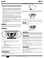
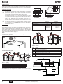
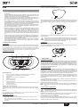
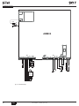
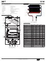
3.5 Electrical connections
B
The unit must be connected to an efficient earthing system in conformity with
the current safety standards. Have the efficiency and suitability of the earthing
system checked by professionally qualified personnel; the Manufacturer declines any liability for damage caused by failure to earth the system.
The water heater is prewired and provided with a "Y" type cable (without plug)
for connection to the electric line . The connections to the grid must be made
with a permanent connection and equipped with a double-pole switch with contact gap of at least 3 mm, interposing fuses of max. 3A between the water heater and the line . Make sure to respect the polarities (LINE: brown wire /
NEUTRAL: blue wire / EARTH: yellow/green wire) in connections to the electric
line.
B
45.6
Important
The unit's power cable must not be changed by the user. If damaged, turn the
unit off and have the cable replaced by professionally qualified personnel. In
case of replacement , only use "HAR H05 VV-F" 3x0.75 mm2 cable with max.
external diameter of 8 mm.
3.6 Fume ducts
68
100
60
010006X0
010007X0
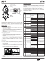
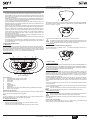
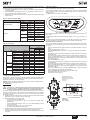
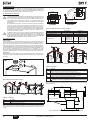
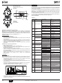
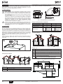
fig. 6 - Starting accessory for coaxial ducts
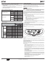
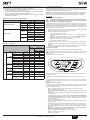
Table. 2 - Baffles for coaxial ducts
Coaxial 60/100
Coaxial 80/125
Max. permissible length
4m
10 m
Reduction factor 90° bend
1m
0.5 m
Reduction factor 45° bend
0.5 m
0.25 m
0÷2m
Model
SKY F 11 = Ø43
SKY F 14 = Ø50
SKY F 17 = Ø50
0÷3m
Model
SKY F 11 = Ø43
SKY F 14 = Ø50
SKY F 17 = Ø50
2÷4m
no baffle
3 ÷ 10 m
no baffle
Important
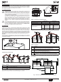
The unit is a "C type" with sealed chamber and forced draught, the air inlet and fume outlet must be connected to one of the following extraction/suction systems. The unit is approved for operation with all the Cny flue configurations given on the dataplate. Some
configurations may be expressly limited or not permitted by law, standards or local regulations. Before installation, check and carefully follow the instructions. Also, comply with
the instructions on the positioning of wall and/or roof terminals and the minimum distances from windows, walls, ventilation openings, etc.
118
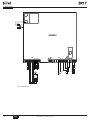
The gas must be connected to the respective union (see figure on cover) in conformity
with the current regulations, with a rigid metal pipe or with a continuous flexible s/steel
tube, installing a gas cock between the system and water heater . Make sure all the gas
connections are tight.
60
100
3.4 Gas connection
Baffle to use
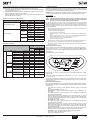
Connection with separate pipes
Baffles
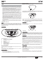
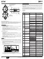
Unit operation requires fitting the baffles supplied. Make sure the right baffle (when used)
is fitted and correctly positioned.
A
2
C5x
B2x
C3x
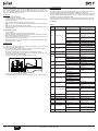
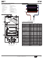
fig. 7 - Examples of connection with separate pipes (
max 50 cm
1
C1x
= Air /
= Fumes)
Table. 3 - Typology
A Baffle replacement with unit not installed
Connection with coaxial pipes
Type
Description
C1X
Wall horizontal exhaust and intake. The inlet/outlet terminals must be concentric or close enough to be
undergo similar wind conditions (within 50 cm)
C3X
Roof vertical exhaust and intake. Inlet/outlet terminals like for C12
C5X
Wall or roof exhaust and intake separate or in any case in areas with different pressures. The exhaust
and intake must not be positioned on opposite walls.
C6X
Intake and exhaust with separately certified pipes (EN 1856/1)
B2X
Intake from installation room and wall or roof exhaust
IMPORTANT - THE ROOM MUST BE PROVIDED WITH APPROPRIATE VENTILATION
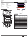
For connection of the separate ducts, fit the unit with the following starting accessory:
C1X
C3X
C3X
C3X
fig. 5 - Examples of connection with coaxial pipes (
C1X
= Air /
C1X
= Fumes)
120
82
82
Type
Description
C1X
Wall horizontal exhaust and inlet
C3X
Roof vertical exhaust and inlet
136
Table. 1 - Typology
For coaxial connection, fit the unit with one of the following starting accessories. For the
wall hole dimensions, refer to the figure on the cover.
fig. 8 - Starting accessory for separate ducts code 010031X0
10
EN
cod. 3540Z101 - 09/2011 (Rev. 00)