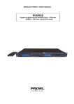
1
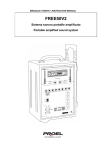
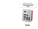
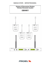
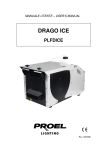
RMW10 Wireless System RMW10 INDICE 1. Precauzioni d’uso ................................................................................................................................................. 3 2. Descrizione ............................................................................................................................................................ 6 3. a) b) c) d) 4. Funzioni e Controlli............................................................................................................................................... 6 Pannello Frontale RMW10................................................................................................................................. 6 Pannello posteriore RMW10 .............................................................................................................................. 7 Trasmettitore a mano WMP ............................................................................................................................... 7 Trasmettitore bodypack WHP ............................................................................................................................ 8 Operazioni .............................................................................................................................................................. 9 Ricevitore RMW10 ............................................................................................................................................. 9 Scansione Automatica ....................................................................................................................................... 9 Selezione manuale della frequenza .................................................................................................................. 9 Regolazione del Livello in uscita ....................................................................................................................... 9 Funzione Mute ................................................................................................................................................... 9 Squelch Control ............................................................................................................................................... 10 b) Trasmettitore WHP / WMP .............................................................................................................................. 10 Selezione della frequenza ............................................................................................................................... 10 Funzione Lock ................................................................................................................................................. 10 Batterie............................................................................................................................................................. 10 a) 5. Installazione ......................................................................................................................................................... 11 6. Tabella Frequenze (798.000-827.000MHZ) ........................................................................................................ 12 7. Caratteristiche Tecniche .................................................................................................................................... 12 INDEX 1. Safety Instructions .............................................................................................................................................. 14 2. Description .......................................................................................................................................................... 17 3. a) b) c) d) 4. Functions and Controls ...................................................................................................................................... 17 Front Panel RMW10 ........................................................................................................................................ 17 Rear Panel RMW10 ......................................................................................................................................... 18 Handheld Transmitter WMP ............................................................................................................................ 18 Body Pack Transmitter .................................................................................................................................... 19 Operation ............................................................................................................................................................. 20 Receiver RMW10 ............................................................................................................................................ 20 Automatic scan ................................................................................................................................................ 20 Manual frequency selection ............................................................................................................................. 20 Output level control .......................................................................................................................................... 20 Mute function ................................................................................................................................................... 20 Squelch Control ............................................................................................................................................... 21 b) Transmitter WMP/WHP .................................................................................................................................. 21 Frequency selection......................................................................................................................................... 21 RF level Selection ............................................................................................................................................ 21 Lock Function .................................................................................................................................................. 21 Mute function ................................................................................................................................................... 21 Battery.............................................................................................................................................................. 21 a) 5. Installation ........................................................................................................................................................... 22 6. Frequency Table (798.000-827.000MHZ) ........................................................................................................... 23 7. Technical Specifications .................................................................................................................................... 23 2 RMW10 1. Precauzioni d’uso AVVERTENZA: Per ridurre il rischio di folgorazione, non rimuovere il coperchio (o il pannello posteriore). All’interno non sono contenute parti riparabili dall’utente; affidare la riparazione a personale qualificato. ATTENZIONE: Per ridurre il rischio d’incendio o di folgorazione, non esporre questo apparecchio alla pioggia o all’umidità. Questo simbolo, ove compare, segnala la presenza di un voltaggio pericoloso non isolato all’interno del corpo dell’apparecchio, voltaggio sufficiente a costituire un rischio di folgorazione. Questo simbolo, ove appare, segnala importanti istruzioni d’uso e manutenzione nel testo allegato. Leggere il manuale. RACCOMANDAZIONI Tutte le istruzioni di sicurezza e funzionamento devono essere lette prima di mettere in funzione l’apparecchio. Conservare le istruzioni Le istruzioni di sicurezza e di funzionamento devono essere conservate per un futuro riferimento. Il presente manuale è parte integrante del prodotto e lo deve accompagnare in caso di eventuali cambi di proprietà. In questo modo il nuovo proprietario potrà conoscere le istruzioni relative a installazione, funzionamento e sicurezza. Prestare attenzione Tutte le avvertenze sull’apparecchio e nelle istruzioni di funzionamento devono essere seguite fedelmente. Osservare tutti gli avvertimenti. Seguire le istruzioni: Tutte le istruzioni per il funzionamento e per l’utente devono essere seguite. Le note precedute dal simbolo contengono importanti informazioni sulla sicurezza: leggerle con particolare attenzione. ISTRUZIONI DI SICUREZZA IN DETTAGLIO. Acqua ed umidità L’apparecchio non deve essere utilizzato in prossimità di acqua (per es. vicino a vasche da bagno, lavelli da cucina, in prossimità di piscine ecc.). Calore L’apparecchio deve essere posto lontano da fonti di calore come radiatori, termostati, asciuga biancheria, o altri apparecchi che producono calore. Alimentazione L’apparecchio deve essere collegato soltanto al tipo di alimentazione descritto nelle istruzioni d’uso o segnalato sull’apparecchio. Se la spina in dotazione non combacia con la presa, rivolgersi ad un elettricista per farsi installare una presa appropriata. Messa a terra o polarizzazione Si devono prendere precauzioni in modo tale che la messa a terra e la polarizzazione dell’apparecchio non siano pregiudicate. Le parti metalliche dell’apparecchiatura sono collegate a massa tramite il cavo d’alimentazione. Se la presa utilizzata per alimentazione non possiede collegamento a massa, rivolgersi ad un elettricista qualificato per fare collegare l’apparato a massa tramite il terminale. 3 RMW10 Protezione del cavo di alimentazione Il cavo di alimentazione elettrica deve essere installato in modo che non venga calpestato o pizzicato da oggetti posti sopra o contro, prestando particolare attenzione a cavi e spine, prese a muro. Pulizia Quando l’unità deve essere pulita, è possibile eliminare la polvere utilizzando un getto d’aria compressa o un panno inumidito. Non pulire l’unità utilizzando solventi quali trielina, diluenti per vernici, fluidi, alcol, fluidi ad alta volatilità o altri liquidi infiammabili. Periodi di non utilizzo Il cavo di alimentazione dell’apparecchio deve essere staccato dalla presa se rimane inutilizzato per un lungo periodo. Ingresso di liquidi o oggetti Fare attenzione a far cadere oggetti e o liquidi nel corpo dell’apparecchio. Uso sicuro della linea d’alimentazione Quando si scollega l’apparato alla rete tenere saldamente sia la spina che la presa. Quando l’unità non viene utilizzata per un periodo prolungato, interrompere l’alimentazione estraendo la spina dalla presa dell’alimentazione. Per evitare danni alla linea d’alimentazione dell’apparato, non mettere in trazione il cavo d’alimentazione e non utilizzare un cavo attorcigliato. Per evitare il danneggiamento del cavo d’alimentazione dell’apparato, assicurarsi che questo non venga calpestato o schiacciato da oggetti pesanti. Spostamento dell’unità Prima di ogni spostamento, verificare che l’unità sia spenta. Il cavo d’alimentazione deve essere estratto dalla presa, così come i collegamenti dell’unità con altre linee. Non smontare l’unità Non tentare di smontare né riparare da soli l’unità. Per qualsiasi problema non risolvibile con l’aiuto del presente manuale, rivolgersi a un tecnico qualificato o consultare la nostra compagnia. Qualsiasi uso non appropriato può causare incendi o scosse elettriche. Malfunzionamenti Non tentare mai di eseguire riparazioni diverse da quelle descritte nel presente manuale. Contattare un centro di servizio autorizzato o del personale altamente qualificato nei seguenti casi: - Quando l’apparato non funziona o funziona in modo anomalo. - Se il cavo d’alimentazione o la spina sono danneggiati. - Sono penetrati oggetti estranei o è stato versato del liquido nell’apparecchio. - L’apparecchio è stato esposto alla pioggia. - L’apparecchio non sembra funzionare normalmente o presenta un evidente cambiamento nelle prestazioni. - L’apparecchio è caduto, o il corpo è danneggiato. Manutenzione L’utente non deve tentare di riparare l’apparecchio al di là di quanto descritto nelle istruzioni di funzionamento. Ogni altra riparazione deve essere affidata a personale specializzato. 4 RMW10 IMPORTANTI NORME DI SICUREZZA Installare seguendo le istruzioni. Il voltaggio d’alimentazione dell’unità è abbastanza elevato: per evitare il rischio di scosse elettriche, non installare, collegare o sconnettere l’alimentazione quando l’apparato è acceso. Non aprire mai l’apparecchiatura: all’interno non esistono parti utilizzabili dall’utente. Se si avverte uno strano odore proveniente dall’apparato, spegnerlo immediatamente e sconnettere il cavo dell’alimentazione. Non ostruire le griglie di ventilazione dell’apparato. Evitare che l’unità lavori in sovraccarico per tempo prolungato. Non forzare i comandi (pulsanti, controlli, ecc.). Per ragioni di sicurezza, non annullare il collegamento a massa della spina. Il collegamento a massa è necessario per salvaguardare la sicurezza dell’operatore. Utilizzare unicamente i connettori e gli accessori specificati dal produttore. In presenza di temporali con fulmini o quando l’apparato non è utilizzato, estrarre la spina d’alimentazione dalla presa. Per prevenire il rischio di incendi e scosse elettriche, è necessario tenere l’apparato lontano da spruzzi e gocce. Sopra l’apparato non devono essere collocati vasi o altri oggetti contenenti liquidi. In caso si verifichino interferenze nel circuito di provenienza, il valore di THD sarà superiore al 10%. Non installare questo apparato in una libreria o in altri luoghi a spazio ristretto. PROEL S.p.A. declina ogni responsabilità in caso di scorretta installazione dell’unità. 5 RMW10 Grazie per aver scelto un prodotto PROEL e della fiducia riposta nel nostro marchio, sinonimo di professionalità, accuratezza, elevata qualità ed affidabilità. Tutti i nostri prodotti sono conformi alle normative CE per utilizzazione continua in impianti di diffusione sonora. 2. Descrizione Il sistema radiomicrofonico RMW10 è composto da 3 parti: ricevitore RMW10, trasmettitore a mano WMP e trasmettitore tascabile WHP, riponibili nella comoda custodia in ABS in dotazione. Il sistema opera su 144 frequenze selezionabili nella banda 798 ÷ 827MHz (UHF) con tecnologia PLL e contemporaneamente possono funzionare fino a 10 sistemi radiomicrofonici. La migliore ricezione del segnale emesso dal trasmettitore è costantemente garantita dal sistema Diversity delle antenne in ricezione, controllato tramite un apposito microprocessore. Il ricevitore ha caratteristiche e prestazioni notevolmente evolute, fornendo la massima qualità in ogni tipo di applicazione. E’ alloggiato in un case in metallo da ½ unità rack e può essere installato in rack standard da 19” tramite kit di montaggio opzionale. E’dotato di un ampio display LCD in grado di visualizzare la frequenza di lavoro selezionata, l’intensità del segnale in radiofrequenza ricevuta e del segnale audio in uscita, nonché la visualizzazione a distanza dello stato di carica-batterie del trasmettitore. Il trasmettitore palmare presenta: display con indicazione di carica della batteria, canale e gruppo, capsula microfonica dinamica, case in materiale plastico antiurto ed antigraffio con antenna trasmittente integrata. Funzionamento con due batterie stilo tipo AA da 1,5V, 18 ore di massima autonomia con uso continuo. Il trasmettitore bodypack presenta: display con indicazione di carica della batteria, canale e gruppo. Microfono headset a condensatore electret a corredo, case in materiale plastico antiurto ed antigraffio con antenna trasmittente integrata. Funzionamento con due batterie stilo tipo AA da 1,5V, 18 ore di massima autonomia con uso continuo. 3. Funzioni e Controlli a) Pannello Frontale RMW10 1. Interruttore d’accensione 2. Tasti UP- DN (Down) Nella modalità MENU permette di scegliere i valori. 3. Display Il display LCD mostra il livello di segnale a radio frequenza (RF), il livello di segnale audio (AF) ricevuti, il livello di carica della batteria del trasmettitore, il n° di GRUPPO, il n° di CANALE, l’antenna che in quell’istante riceve meglio il segnale e la frequenza di lavoro. 4. MENU Premendo questo tasto si passa ciclicamente alle seguenti funzioni: GROUP / CHANNEL / PL / MUTE / SQUELCH. 5. MEM Avvia la funzione di AUTO SCAN e quella di MEMO. 6 RMW10 b) Pannello posteriore RMW10 1. Connettore antenna A Inserire una delle 2 antenne in dotazione nel connettore, avvitare a fondo la ghiera e posizionare l’antenna verticalmente. 2. Connettore antenna B Vedi 1 3. Uscita Audio bilanciata su XLR Si consiglia l’utilizzo di quest’uscita, soprattutto quando bisogna coprire lunghe tratte tra il ricevitore RMW10 e il mixer/amplificatore. A tale scopo munirsi di un cavo schermato bilanciato e connettore XLR femmina. 4. Uscita Audio sbilanciata su Jack 6.3 mono Al fine di mantenere alta la qualità del segnale, non utilizzare questa uscita per coprire lunghe tratte di linea tra il ricevitore RMW10 e il mixer/amplificatore. Per il collegamento utilizzare un Jack mono da 6.3 e un cavo schermato sbilanciato. 5. Connettore alimentazione VDC Collegare a questo connettore l’alimentatore AC/DC precedentemente collegato alla presa di rete 220-230VAC. c) Trasmettitore a mano WMP 1. Griglia Protegge la capsula microfonica. 2. Display Il display LCD mostra: simbolo d’antenna (se TX e RX sono agganciati), frequenza di lavoro, livello di carica della batteria, CANALE, GRUPPO, potenza di trasmissione (PL), LOCK. 3. CH/ON Premendo per un secondo questo tasto il trasmettitore si accende, alle successive pressioni si passa ciclicamente alle seguenti funzioni: CHANNEL / GROUP / PL / LOCK. Per spegnere il trasmettitore premere il tasto per un secondo. 4. SELECT Nella modalità funzioni permette di scegliere i valori. 5. Vano Batterie Svitare il corpo del microfono inserire 2 batterie stilo AA 1,5V o ricaricabili (optional) rispettando la polarità, riavvitare. 6. Jack di carica Per la ricarica delle batterie ricaricabili, collegare il caricabatterie (opzionale) a questo jack. 7. Antenna La copertura dell’antenna (ad esempio con le mani), comporta un’attenuazione del segnale emesso, con possibili fruscii o perdite di trasmissione. 7 RMW10 d) Trasmettitore bodypack WHP 1. Display Il display LCD mostra: simbolo d’antenna (se TX e RX sono agganciati), frequenza di lavoro, livello di carica della batteria, CANALE, GRUPPO, potenza di trasmissione (PL), LOCK. 2. CH/ON Premendo per un secondo questo tasto il trasmettitore si accende, alle successive pressioni si passa ciclicamente alle seguenti funzioni: CHANNEL / GROUP / PL / LOCK. Per spegnere il trasmettitore premere il tasto per un secondo. 3. SELECT Nella modalità funzioni permette di scegliere i valori. 4. Jack di carica Per la ricarica delle batterie ricaricabili, collegare il caricabatterie (opzionale) a questo jack. 5. Connettore Mini 4P Collegare i microfoni lavalier ed headset a questo connettore. Tramite questo connettore è possibile collegare al trasmettitore una chitarra, un basso una tastiera ecc. Pin 1: massa Pin 2: +5V Pin 3: Audio Pin 4: 6. Vano Batterie Aprire il vano e inserire 2 batterie stilo AA 1,5V o ricaricabili (optional) rispettando la polarità, chiudere. 7. Clip Aggancio per cintura. 8. Antenna La copertura dell’antenna (ad esempio con le mani), comporta un’attenuazione del segnale emesso, con possibili fruscii o perdite di trasmissione. 8 RMW10 4. Operazioni a) Ricevitore RMW10 A: Gruppo di frequenza B: Canale C: Mute (quando la funzione Mute è attiva il simbolo è mostrato a display) D: Frequenza selezionata E: Livello di carica della batteria del trasmettitore F: Livello dell’audio ricevuto G: Livello del segnale ricevuto Scansione Automatica Premendo per un secondo il tasto MEM il ricevitore inizia la scansione automatica su tutta la banda. Durante la scansione, l’audio è silenziato e il display mostra la frequenza corrente. Nel momento in cui un segnale viene ricevuto la scansione si arresta e il valore di frequenza sul display lampeggia, premere MEM per memorizzare la frequenza. Se si vuole continuare la scansione, premere il tasto UP. Selezione manuale della frequenza Premendo il tasto MENU l’indicatore GROUP inizia a lampeggiare, scegliere il gruppo di frequenza desiderato mediante i tasti UP e DO, memorizzare il gruppo scelto mediante il tasto MEM. Premendo due volte il tasto MENU l’indicatore CHANNEL inizia a lampeggiare, scegliere il canale di frequenza desiderato mediante i tasti UP e DO, memorizzare il gruppo scelto mediante il tasto MEM. Regolazione del Livello in uscita Entrare nella modalità Livello linea premendo tre volte il tasto MENU, il display mostrerà il simbolo PL seguito dal valore corrente del livello: 0 = 500mV - 1 = 300mV - 2 = 150mV. Selezionare il livello desiderato con i tasti UP e DN, confermare con il tasto MEM. Funzione Mute Premendo quattro volte il tasto MENU il simbolo MUTE inizia a lampeggiare, utilizzando i tasti UP e DN attivate o disattivare la funzione, premere il tasto MEM per convalidare la scelta. Quando la funzione Mute è attiva l’audio in uscita risulta silenziato. Funzione MUTE OFF Funzione MUTE ON 9 RMW10 Squelch Control Entrare nella modalità SQUELCH premendo cinque volte il tasto MENU, il display mostrerà il simbolo SI seguito dal valore corrente della soglia: Numero Soglia di Squelch 1 95,0 dB 2 91,7 dB 3 88,3 dB 4 85,0 dB 5 81,7 dB 6 78,3 dB 7 75,0 dB 8 71,7 dB 9 68,3 dB 10 65,0 dB Selezionare il livello desiderato con i tasti UP e DO, confermare con il tasto MEM. Finche il segnale ricevuto ha un livello inferiore alla soglia impostata, il ricevitore resterà silenziato, questa funzione elimina il rumore di fondo nelle pause. Fare attenzione al livello impostato, una soglia troppo elevata rischia di tagliare anche il segnale desiderato. b) Trasmettitore WHP / WMP Premendo per un secondo questo tasto il trasmettitore si accende mostrando la frequenza corrente e il livello di carica della batteria, alle successive pressioni si passa ciclicamente alle seguenti funzioni: CHANNEL - GROUP - PL - LOCK / UNLOCK. Per spegnere il trasmettitore premere il tasto per un secondo. Selezione della frequenza Entrare nella modalità CANALE premendo il tasto CH/ON, il display mostrerà il simbolo CH seguito dal valore corrente di canale, mediante il tasto SELECT selezionare il canale desiderato, premendo nuovamente il tasto CH/ON si entra nella modalità GRUPPO, il display mostrerà il simbolo GP seguito dal valore corrente di gruppo, mediante il tasto SELECT selezionare il gruppo desiderato. Dopo alcuni secondi dall’ultima digitazione il display si riporta sulla schermata iniziale. Selezione del livello di potenza RF. Entrare nella modalità POTENZA premendo tre volte il tasto CH/ON, il display mostrerà il simbolo PL seguito dal livello di potenza corrente, mediante il tasto SELECT selezionare il livello desiderato, 0 : output 5dB , 1 : output 10dB , 2 : output 15dB . Dopo alcuni secondi dall’ultima digitazione il display si riporta sulla schermata iniziale. Funzione Lock Entrare nella modalità Look/unlock premendo quattro volte il tasto CH/ON, il display mostrerà Look o unlock a seconda di quale è settato correntemente, mediante il tasto SELECT selezionare o deselezionare il blocco. Dopo alcuni secondi dall’ultima digitazione il display si riporta sulla schermata iniziale. Quando il Trasmettitore è bloccato il dispositivo permette la scansione delle funzioni mostrando sul display i parametri correnti, ma non permette la loro modifica le uniche operazioni consentite sono: accensione, spegnimento, impostazione del MUTE e de-selezione del lock. Funzione Mute Premendo per più di un secondo il tasto SELECT, viene attivata la funzione MUTE e la scritta MUTE compare in maniera permanente sul display. Premendo nuovamente il tasto SELECT la scritta scompare e la funzione viene deselezionata. Quando la funzione MUTE è attiva il trasmettitore non trasmette. Batterie Quando le batterie sono scariche l’indicatore di livello batterie lampeggia, sostituire (o ricaricare, nel caso di batterie ricaricabili) le batterie. Utilizzare batterie AA 1,5V. Per la ricarica delle batterie utilizzare il carica-batterie opzionale, collegato nell’apposito connettore. Generalmente il tempo di ricarica è di circa 6 ore. Durante la ricarica l’indicatore di livello batterie è “dinamico”. 10 RMW10 5. Installazione Collegare l’uscita del ricevitore RMW10 ad un mixer/amplificatore, utilizzando l’uscita bilanciata o sbilanciata a seconda dei casi. Connessione di tipo bilanciata: Connessione di tipo sbilanciata: Connessione di tipo sbilanciato con jack mono Connessione RCA Dopo aver collegato le antenne, collegare l’adattatore AC/DC al RMW10 e alla presa di rete: Accendere il ricevitore Inserire le batterie nel trasmettitore e accenderlo. Esistono 2 modi per impostare la frequenza di lavoro: 1) Selezionare manualmente la stessa frequenza sul ricevitore e sul trasmettitore (vedi paragrafo 3 e 4). 2) Impostare manualmente la frequenza desiderata sul trasmettitore (vedi paragrafo 4) e avviare la scansione automatica sul ricevitore (vedi paragrafo 3). Nota: Se ci sono più sistemi radiomicrofonici che lavorano contemporaneamente, il ricevitore potrebbe arrestarsi sulla frequenza di lavoro di un altro trasmettitore, continuare la scansione finche la frequenza rilevata non è quella del trasmettitore che vogliamo associare al ricevitore in questione. 11 RMW10 6. Tabella Frequenze (798.000-827.000MHZ) 1 2 3 4 5 6 7 8 9 10 11 12 Group1 Group2 Group3 Group4 Group5 Group6 Group7 Group8 Group9 Group10 Group11 798.125 798.325 798.525 798.725 798.925 799.125 799.325 799.525 799.725 799.925 800.125 Group12 800.325 800.525 800.725 800.925 801.125 801.325 801.525 801.725 801.925 802.125 802.325 802.525 802.725 802.925 803.125 803.325 803.525 803.725 803.925 804.125 804.325 804.525 804.725 804.925 805.125 805.325 805.525 805.725 805.925 806.125 806.325 806.525 806.725 806.925 807.125 807.325 807.525 807.725 807.925 808.125 808.325 808.525 808.725 808.925 809.125 809.325 809.525 809.725 809.925 810.125 810.325 810.525 810.725 810.925 811.125 811.325 811.525 811.725 811.925 812.125 812.325 812.525 812.725 812.925 813.125 813.325 813.525 813.725 813.925 814.125 814.325 814.525 814.725 814.925 815.125 815.325 815.525 815.725 815.925 816.125 816.325 816.525 816.725 816.925 817.125 817.325 817.525 817.725 817.925 818.125 818.325 818.525 818.725 818.925 819.125 819.325 819.525 819.725 819.925 820.125 820.325 820.525 820.725 820.925 821.125 821.325 821.525 821.725 821.925 822.125 822.325 822.525 822.725 822.925 823.125 823.325 823.525 823.725 823.925 824.125 824.325 824.525 824.725 824.925 825.125 825.325 825.525 825.725 825.925 826.125 826.325 826.525 826.725 Nel caso in cui di più sistemi radiomicrofonici lavorino contemporaneamente, per evitare interferenze, utilizzare le seguenti frequenze: Group1 Group2 Group3 Group5 Group7 Group8 Group12 CH 1 798.125 798.325 798.925 799.325 CH 2 800.725 802.725 CH 4 805.725 CH 5 807.925 CH 6 811.525 CH 8 815.725 - 7. Caratteristiche Tecniche MODEL Channel Frequency band: Receiver type: Frequency response: Frequency stability: T.H.D: Modulation mode S/N Ratio Dynamic RF sensitivity Audio output Power Supply Dimensions (WxDxH) Weight RMW10 Multi-channels, up 144 frequency preset for each frequency band UHF 798 ÷ 827MHz PLL UHF Synthesized 50Hz - 15KHz (-3dB) 0,005% (-10°C - 50°C) < 0,8% 1KHZ FM (F3E) > 90dB >100dB -100dBm/30dB SINAD 250 mv Symmetrical 750 mV Asymmetrical DC 12V-500 mA 230 Vca adaptor 210 mm x 156 mm x 44 mm 0,95Kg MODEL Trasmission mode Frequency band: Frequency response: Frequency stability: T.H.D: Modulation mode RF Output power Dynamic Tone Frequency Max deviaton Battery Microphone type Dimensions (WxDxH) Weight WHP PLL Multi-channels, up 144 frequency preset for each frequency band UHF 798 ÷ 827MHz 50Hz - 15KHz (-3dB) 0,005% (-10°C - 50°C) < 0,8% 1KHZ FM (F3E) max 50mW (adjustable 3 levels) >100dB 30-33 KHz +/-35KHz “AA” type x 2 Hcm38 ( optional ) 66 mm. x 103 mm. x 23 mm 0,2Kg - 12 RMW10 MODEL Trasmission mode Frequency band: Frequency response: Frequency stability: T.H.D: Modulation mode RF Output power Dynamic Tone Frequency Max deviaton Battery Microphone type Dimensions (WxDxH) Weight WMP PLL Multi-channels, up 144 frequency preset for each frequency band UHF 798 ÷ 827MHz 50Hz - 15KHz (-3dB) 0,005% (-10°C - 50°C) < 0,8% 1KHZ FM (F3E) Max 10 mW >100dB 30-33 KHz +/-35KHz “AA” type x 2 Dynamic cardiod 277 mm x 36,5 mm diameter 0,2Kg AVVERTENZA Questo apparecchio radio è inteso per uso professionale nell’ambito dell’intrattenimento e applicazioni similari. Questo apparecchio potrebbe essere in grado di funzionare a frequenze non autorizzate nella regione in cui si trova l’utente. Si consiglia di rivolgersi alle autorità competenti per ottenere le informazioni necessarie relative alle frequenze autorizzate nella propria regione per i sistemi radiomicrofonici. In alcuni casi potrebbe essere necessaria una licenza ministeriale per l’uso di questo apparecchio. Per i possibili requisiti rivolgersi alle autorità competenti. L’utente si assume l’esclusiva responsabilità per l’acquisizione della licenza delle attrezzature senza fili e la licenziabilità dipende dalla classificazione e dall’applicazione dell’utente e dalla frequenza selezionata. Ai sensi del D. Lgs. 269/2001 art.6 comma 3 Il prodotto è conforme alla Direttiva 89/336/CEE (Compatibilità Elettromagnetica) e successive modifiche 92/31/CEE e 93/68/CEE. Inoltre, è conforme alla Direttiva 73/23/CEE (Bassa Tensione) e successive modifiche 93/68/CEE. La Proel SpA persegue una politica di costante ricerca e sviluppo, di conseguenza si riserva il diritto di apportare miglioramenti ai prodotti esistenti, senza preavviso e in qualunque momento. La Proel SpA non assume alcuna responsabilità sull’uso ed alle applicazioni dei prodotti o circuiti riportati su questo manuale. PROEL S.p.A. Via alla Ruenia 37/43 64027 Sant’Omero (Te) – Italy Tel: +39 0861 81241 Fax: +39 0861 887862 [email protected] 13 RMW10 1. Safety Instructions CAUTION: To reduce the risk of electric shock do not the remove cover or back panel. No user serviceable parts inside. Refer servicing to qualified personnel only. WARNING: To reduce the risk of fire or electric shock, do not expose this apparatus to rain or moisture. This symbol is intended to alert the user of the presence of un-insulated dangerous voltage within the product enclosure that may be of sufficient magnitude to constitute a risk of electric shock to persons. This symbol is intended to alert the user of the presence of important operating and maintenance (servicing) instruction in the literature accompanying the appliance. Please carefully read the owner’s manual. INSTRUCTIONS All safety and operating instructions should be read before the product is operated. Retain these instructions All safety and operating instructions should be retained for future reference. This owner’s manual should be considered as a part of the product and it must accompany it every time, and delivered to the new user when this product is sold. In this way the new owner will be aware of all the installation, operating and safety instructions. Heed all warnings All warnings on the product and in owner’s manual should be adhered to. Follow all instructions All operating and user’s instructions must be followed. Sentences preceded by symbol contain important safety instruction. Please read it carefully. DETAILED SAFETY INSTRUCTIONS Water and moisture This apparatus should not be used near water (i.e. bathtub, kitchen sink, swimming pools, etc.). Heat This apparatus should be placed away from heat sources, like radiators, heat registers, stoves or other products (including amplifiers) that produce heat. Power sources This apparatus should only be connected to power source type specified in this owner’s manual or on the unit. If the supplied AC power cable plug is different from the wall socket, please contact an electrician to change the AC power plug. Grounding or Polarization: All precautions must be observed to do not defeat grounding or polarization. Unit metal parts are grounded through the AC power cord. If the AC power outlet doesn’t have grounding, consult an electrician for outlet grounding. 14 RMW10 Power cord protection The power cord should be positioned in a way it will not be stepped on or pinched by items placed upon or against it, paying particular attention to cable connected to the plugs, sockets and wall outlets. Cleaning: The unit can be cleaned with compressed air or with a soft damp cloth. Do not clean the unit with solvents such as trichloroethylene, thinners, alcohol, or other fluids with very strong volatility and flammability. Long periods where the unit is not being used If not used for long periods, the unit should be disconnected from the AC power supply. Objects or liquid entry inside the unit Be careful that no objects fall or liquid is spilled inside the unit through ventilation openings. Safe power line use Hold the plug and the wall outlet while disconnecting the unit from AC power. If the unit will not be used for a long period of time, please unplug the power cord from AC power outlet. To avoid unit power cord damage, please do not strain the AC power cable and do not bundle it. In order to avoid unit power cord damage, please ensure that the power cord is not stepped on or pinched by heavy objects. Unit relocation Before the unit is relocated please ensure the unit is switched off. The power cord must be unplugged from the wall outlet and all connection cables should be disconnected. Do not open this unit Do not attempt to open or to repair this unit by yourself. For any problems not described in this owner’s manual, please refer to qualified personnel only or consult PROEL or your National PROEL Distributor. Any improper operation could result in fire or electric shock. Damages requiring services Do not attempt any operations not described in this user’s manual. In the following cases please refer to an authorised maintenance centre or skilled personnel: - When the unit works improperly or it does not work at all. - If power cord or plug are damaged. - If liquid has spilled, or objects have fallen into the unit. - If the unit has been exposed to rain. - If the unit does not operate normally or it exhibits a marked change in performance. - If the product has been dropped or it has been damaged in any way. Maintenance The user should not attempt any maintenance operation not described in this user’s manual. All maintenance should be carried out by qualified personnel. 15 RMW10 IMPORTANT SAFETY INSTRUCTIONS: Install this unit following owner’s manual instructions. Do not install, connect or disconnect power supply when the unit is powered, to avoid electric shock. Do not open the unit: there are no user serviceable parts inside. If you detect any strong smell emanating from the unit, immediately turn it off and disconnect the AC power cord. Do not block the unit ventilation openings. Avoid using this unit in overload for a long period. Do not force the commands (switches, controls, etc.) For safety reason, do not defeat or bypass the grounding connection. Grounding is important for user safety. Only use connectors and accessories suggested by the manufacturer. . This unit should be placed in a rack and kept far from: - Wet / humid areas - Direct exposure to heat sources (like sun light) - Non properly ventilated places Disconnect the power cord during storms or when the unit is not being used. In order to prevent fire and electric shock risks, it is necessary to keep the unit far from liquids. Please do not put cups, vases or other object containing liquids over the unit. In case of interference from source signal, the THD value will raise over 10%. Do not place this unit in confined spaces. PROEL S.p.A. is not responsible for any damage that occurs due to a incorrect installation of the unit. 16 RMW10 Thank you for choosing this PROEL product and for your trust in our brand, synonymous of professionalism, accuracy, high quality and reliability. All our products are CE approved and designed for continuous use in professional systems. 2. Description The RMW10 Wireless Microphone system features 3 units: the RMW10 receiver, WMP handheld transmitter and WHP body pack transmitter. A carrying case is included. This Wireless system operating frequency range covers 144 different UHF frequencies o be selected amongst the following UHF frequency band 798 ÷ 827MHz (UHF) thanks to PLL technology. Up to a maximum of 10 systems can operate contemporaneously. The available Diversity Antenna constantly grants the better transmitter signal thanks to an appropriate microprocessor monitoring. The receiver provides a high quality performance level. The receiver provides a high quality reproduction in many applications and it is hosted in a ½ rack unit metal case (optional fixing kit is available for mounting in a standard 19” rack). The receiver is equipped with an LCD display showing the operating frequency, frequency signal intensity, audio output signal and the transmitter battery level. The LCD screen on the transmitter displays the battery level, the frequency group and the channel frequency. Microphone transmitter is a dynamic cardioid. The body-pack transmitter LCD screen displays the battery charge level, frequency group and the channel frequency. Headset condenser microphone provided, the body pack transmitter is supplied with a plastic, anti-scratch case plus two antenna and two AA 1,5 V batteries with 18 hours autonomy. 3. Functions and Controls a) Front Panel RMW10 1. ON/ OFF Switch 2. UP- DN (Down) keys Allows the frequency value selection. 3. Display Shows the RF signal level, the audio frequency level, the battery level, the frequency group and channel number, the reception of the antenna and best operating frequency. 4. MENU Pressing the menu key activates the following functions (in order): GROUP / CHANNEL / PL / MUTE / SQUELCH. 5. MEM Activates AUTO SCAN and MEMORY functions. 17 RMW10 b) Rear Panel RMW10 1. Antenna A input Insert one of the two antennas (included) and secure by screwing the external metal ring. The antenna should be in vertical position. 2. Antenna B input See point 1 3. XLR Balanced audio output This output recommended for long distance between RMW10 and the mixer. Use a balanced, shielded cable and female XLR connector. 4. 6.3 Jack Mono Unbalanced audio output The unbalanced output should only be used if the RMW10 and the mixer are in close proximity. Use a jack mono 6.3 and a shielded unbalanced cable. 5. VDC Power Connector Connect the power supply cable to the VDC after having connected the plug to the main power supply (220-230Vac). c) Handheld Transmitter WMP 1. 2. Grille for microphone capsule protection Display Displays the Antenna symbol (when TX and RX are coupled), the operating frequency, battery level, channel and frequency group, (PL) transmission power and LOCK. 3. CH/ON Press the Transmitter switch for one second. The transmitter displays the current frequency and the battery charge level. Press this switch again to pass in a cyclic mode to the following functions: CHANNEL - GROUP - PL - LOCK / UNLOCK. To disable the transmitter press and keep pressing for one second. 4. SELECT Allows the selection of the settings in the Function mode. 5. Battery location Unscrew the microphone body to insert two AA 1,5V batteries (rechargeable as option) respecting the polarity. 6. Jack input for battery recharge To recharge rechargeable batteries, connect the battery charger (optional) to this jack input. 7. Antenna Ensure that the antenna is not covered (by hands for example), to avoid signal attenuation, loss or noise. 18 RMW10 d) Body Pack Transmitter 1. Display LCD displays: antenna symbol ( when TX and RX are couplet), operating frequency, charge battery level, CHANNEL, GROUP, power transmission (PL), LOCK. 2. CH/ON Press for one second to switch the Transmitter on. The transmitter displays the current frequency and the battery charge level. Press this switch again to pass in a cyclic mode to the following functions: CHANNEL - GROUP - PL - LOCK / UNLOCK. To disable the transmitter press and keep pressing for one second. 3. SELECT Allows the selection of the settings in the Function mode. 4. Jack for battery recharge purposes To charge rechargeable batteries, connect the battery charger (optional) to this jack input. 5. Mini 4P connector Connect the clip microphone and headset to this connector: guitar, bass, keyboard (etc) .can be connected to this input. Pin 1: massa Pin 2: +5V Pin 3: Audio Pin 4: 6. Battery compartment Open the battery housing and insert two AA 1,5V batteries or rechargeable batteries (optional) respecting the polarity. 7. Clip 8. Antenna Ensure that the antenna is not covered (by hands for example), to avoid signal attenuation, loss or noise. 19 RMW10 4. Operation a) Receiver RMW10 A: Frequency group. B: Channel. C: Mute (symbol is displayed when function mute is activated). D: Selected frequency. E: Transmitter Battery charge level. F: Audio in input level. G: Level of the signal received. Automatic scan Pressing the MEM key for one second, the full band automatic scan is activated. The scan ends when a signal is located. The screen will indicate this frequency. Press MEM to memorise the frequency. To continue the scan press UP. Manual frequency selection Press MENU key to select the GROUP function. Select the frequency group desired using keys UP and DOWN. The selected GROUP can be memorised by pressing the MEM key. Press the MENU Key two times to select the CHANNEL function. Select the frequency group desired using keys UP and DOWN. The selected CHANNEL can be memorised by pressing the MEM key. Output level control Select line level mode pressing the MENU Key 3 times. The display indicates PL and the level current value: 0 = 500mV - 1 = 300mV - 2 = 150mV Select the level using the UP and DN keys and confirm using MEM key. Mute function Press the MENU key 4 times to select the MUTE function. The UP and DN keys will select activate or disable MUTE. Confirm your choice with the MEM key . When the Mute function is active there will be no audio signal output. MUTE FUNCTION OFF MUTE FUNCTION ON 20 RMW10 Squelch Control Enter SQUELCH mode by pressing the MENU key 5 times. The SI symbol with the current level value is displayed: Number 1 2 3 4 5 6 7 8 9 10 Squelch threshold 95,0 dB 91,7 dB 88,3 dB 85,0 dB 81,7 dB 78,3 dB 75,0 dB 71,7 dB 68,3 dB 65,0 dB Select level using the UP and DN keys and confirm pressing with MEM key. If the input signal is below the setting level, the receiver is muted .This eliminates background noise during pause times. Ensure to set such level to avoid to eliminate the signal. b) Transmitter WMP/WHP Press for the CH/ON switch for one second to switch the Transmitter on. The transmitter displays the current frequency and the battery charge level. Press again to pass (in a cyclic mode) to the following functions: CHANNEL - GROUP - PL - LOCK / UNLOCK. To disable the transmitter press and keep pressing for one second. Frequency selection Enter CHANNEL mode, press the CH/ON switch. The CH symbol is displayed along with the current channel value. Use the SELECT button to select the CHANNEL. Use the CH/ON switch to activate the GROUP mode - the symbol GP will be displayed with the current group value. Use the SELECT key to select the GROUP. After a few seconds, the display will return to the main menu screen. RF level Selection Enter the POWER mode pressing the CH/ON button 3 times. The Symbol PL and the current power value are displayed. Use SELECT key to select the output power required. 0 = 5dB ,1 = 10dB , 2 = 15dB . After a few seconds, the display will return to the main menu screen. Lock Function Enter the LOCK/UNLOCK mode by pressing the CH/ON key 4 times. The Lock or Unlock symbol will be displayed. Use the SELECT key to select the setting (LOCK/UNLOCK). After a few seconds, the display will return to the main menu screen. When the transmitter is locked, it is still possible to perform the SCAN function. The display visualise the current setting without allowing any setting modification. When the unit is locked, only the power on/off, MUTE and LOCK functions are accessible. Mute function Press the SELECT button for more than a second will put the unit in MUTE mode. Pressing the SELECT button again will disable the MUTE function. When the MUTED there will be no audio signal output. Battery When batteries are exhausted, the battery level indicator will activate. The batteries should be either replaced or (if rechargeable batteries are used ) recharged. Use 1,5V AA Batteries. To re-charge the batteries, use the optional battery charger with the appropriate connector. Recharging time is generally about 6 hours. While the batteries are recharging, the battery level indicator is will be animated showing that the system is recharging. 21 RMW10 5. Installation Connect the RMW10 receiver to a mixer/amplifier, using the balanced or unbalanced output as follows: Balanced connection: Unbalanced connection: Unbalanced connection with Mono jack RCA connection Connect the antenna, connect the power adaptor to the RMW10 and then to the mains power supply socket Switch on the receiver. Insert the batteries in the transmitter and switch on. There are 2 modes for the operating frequency setting: 1) Manually select the frequency on the receiver and on the transmitter (see points 3 and 4) 2) Set manually the frequency on the transmitter (see paragraph 4) and proceed with automatic scan on the receiver ( see point 3) Note: In the case that many wireless microphone systems operating at the same time, the automatic frequency receiver scan might lock onto the operating frequency of another transmitter. The scan should be continued ensuring the correct combination is selected: receiver 1 coupled with transmitter 1 , receiver 2 coupled with transmitter 2 and so on. 22 RMW10 6. Frequency Table (798.000-827.000MHZ) 1 2 3 4 5 6 7 8 9 10 11 12 Group1 798.125 Group2 798.325 Group3 798.525 Group4 798.725 Group5 798.925 Group6 799.125 Group7 799.325 Group8 799.525 Group9 799.725 Group10 799.925 Group11 800.125 Group12 800.325 800.525 800.725 800.925 801.125 801.325 801.525 801.725 801.925 802.125 802.325 802.525 802.725 802.925 803.125 803.325 803.525 803.725 803.925 804.125 804.325 804.525 804.725 804.925 805.125 805.325 805.525 805.725 805.925 806.125 806.325 806.525 806.725 806.925 807.125 807.325 807.525 807.725 807.925 808.125 808.325 808.525 808.725 808.925 809.125 809.325 809.525 809.725 809.925 810.125 810.325 810.525 810.725 810.925 811.125 811.325 811.525 811.725 811.925 812.125 812.325 812.525 812.725 812.925 813.125 813.325 813.525 813.725 813.925 814.125 814.325 814.525 814.725 814.925 815.125 815.325 815.525 815.725 815.925 816.125 816.325 816.525 816.725 816.925 817.125 817.325 817.525 817.725 817.925 818.125 818.325 818.525 818.725 818.925 819.125 819.325 819.525 819.725 819.925 820.125 820.325 820.525 820.725 820.925 821.125 821.325 821.525 821.725 821.925 822.125 822.325 822.525 822.725 822.925 823.125 823.325 823.525 823.725 823.925 824.125 824.325 824.525 824.725 824.925 825.125 825.325 825.525 825.725 825.925 826.125 826.325 826.525 826.725 In case several wireless microphone systems are operating at the same time, the following frequencies should be used in order to avoid interference: CH 1 CH 2 CH 4 CH 5 CH 6 CH 8 Group1 - Group2 798.325 800.725 807.925 - Group3 805.725 - Group5 798.925 - Group7 799.325 825.725 Group8 816.325 - Group12 802.725 819.525 - Note: Do not use the same frequency for 2 wireless microphone systems. 7. Technical Specifications MODEL Channel Frequency band: Receiver type: Frequency response: Frequency stability: T.H.D: Modulation mode S/N Ratio Dynamic RF sensitivity Audio output Power Supply Dimensions (WxDxH) Weight RMW10 Multi-channels, up 144 frequency preset for each frequency band UHF 798 ÷ 827MHz PLL UHF Synthesized 50Hz - 15KHz (-3dB) 0,005% (-10°C - 50°C) < 0,8% 1KHZ FM (F3E) > 90dB >100dB -100dBm/30dB SINAD 250 mv Symmetrical 750 mV Asymmetrical DC 12V-500 mA 230 Vca adaptor 210 mm x 156 mm x 44 mm 0,95Kg MODEL Transmission mode Frequency band: Frequency response: Frequency stability: T.H.D: Modulation mode RF Output power Dynamic Tone Frequency Max deviaton Battery Microphone type Dimensions (WxDxH) Weight WHP PLL Multi-channels, up 144 frequency preset for each frequency band UHF 798 ÷ 827MHz 50Hz - 15KHz (-3dB) 0,005% (-10°C - 50°C) < 0,8% 1KHZ FM (F3E) max 50mW (adjustable 3 levels) >100dB 30-33 KHz +/-35KHz “AA” type x 2 Hcm38 ( optional ) 66 mm. x 103 mm. x 23 mm 0,2Kg - 23 RMW10 MODEL Transmission mode Frequency band: Frequency response: Frequency stability: T.H.D: Modulation mode RF Output power Dynamic Tone Frequency Max deviaton Battery Microphone type Dimensions (WxDxH) Weight WMP PLL Multi-channels, up 144 frequency preset for each frequency band UHF 798 ÷ 827MHz 50Hz - 15KHz (-3dB) 0,005% (-10°C - 50°C) < 0,8% 1KHZ FM (F3E) Max 10 mW >100dB 30-33 KHz +/-35KHz “AA” type x 2 Dynamic cardiod 277 mm x 36,5 mm diameter 0,2Kg WARNING LICENSING INFORMATION Changes or modifications not expressly approved by Proel S.p.A. could void your authority to operate the equipment. Licensing of wireless microphone equipment is the user’s responsibility, and licensability depends on the user’s classification and application, and on the selected frequency. Proel strongly urges the user to contact the appropriate telecommunications authority concerning proper licensing, and before choosing and ordering frequencies. IMPORTANT! This equipment may be capable of operating on some frequencies not authorized in your region. Please contact your national authority to obtain information on authorized frequencies for wireless microphone products in your region. The product is in compliance with Directive 89/336/EEC (Electromagnetic Compatibility) and following modifications 92/31/EEC and 93/68/EEC It is also in compliance with Directive 73/23/EEC (Low Voltage) and following modifications 93/68/EEC. PROEL S.p.A hereby, declares that this wireless microphone system complies with the essential requirements and other relevant provisions of Directive 1999/5/EC. Consult local or national radio spectrum authorities for information on possible restrictions or necessary authorizations before using this Short Range Device. PROEL S.p.A. pursues a policy of continuous research and development. PROEL S.p.A. reserves the right to modify product circuitry and appearance at any moment, without prior notice. PROEL S.p.A. Via alla Ruenia 37/43 64027 Sant’Omero (Te) – Italy Tel: +39 0861 81241 Fax: +39 0861 887862 [email protected] 24 RMW10 25 PROEL S.p.A. (World Headquarters - Factory) Via alla Ruenia 37/43 64027 Sant’Omero (Te) – Italy Tel: +39 0861 81241 Fax: +39 0861 887862 E-mail: [email protected] www.proelgroup.com