1
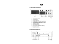
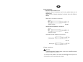
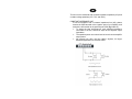
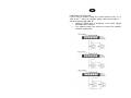
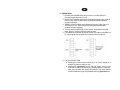
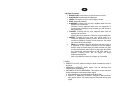
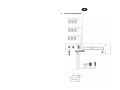
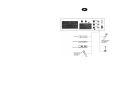
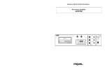
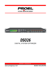
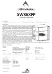
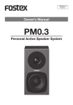
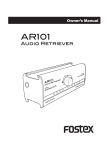
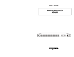
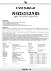
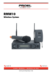
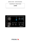
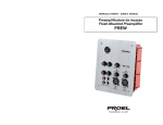
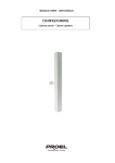
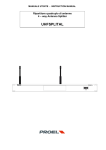
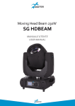
INSTRUCTION MANUAL
PA Combo Amplifier
ACDT90
1.
IMPORTANT SAFETY INSTRUCTIONS
CAUTION:
To reduce the risk of electric shock do not remove cover (or back panel). No
user serviceable parts inside. Refer servicing to qualified personnel only.
WARNING:
To reduce the risk of fire or electric shock, do not expose this apparatus to
rain or moisture.
This symbol is intended to alert the user of the presence of uninsulated
dangerous voltage within the product enclosure that may be of sufficient
magnitude to constitute a risk of electric shock to persons.
This symbol is intended to alert the user of the presence of important operating
and maintenance (servicing) instruction in the literature accompanying the
appliance. Please carefully read the owner’s manual.
INSTRUCTIONS:
All safety and operating instructions should be read before the product is operated.
Retain these instructions:
All safety and operating instructions should be retained for future reference.
This owner’s manual should be considered as a part of the product and it must accompany it
every time, and delivered to the new user when this product is sold. In this way the new owner will
be aware of all the installations, operating and safety instructions.
Heed all warnings:
All warnings on the product and in owner’s manual should be adhered to.
Heed all warnings.
Follow all instructions:
All operating and user’s instructions must be followed.
Sentences preceded by
symbol contain important safety instruction. Please read it carefully.
DETAILED SAFETY INSTRUCTIONS.
Water and moisture:
This apparatus should not be used near water (i.e. bathtub, kitchen sink, swimming pools,
etc.)
Ventilation:
This apparatus should be placed in a position that doesn’t interfere with correct ventilation.
This unit, for example, should not be placed on a bed, sofa cover o similar surfaces that could
cover ventilation openings, or placed in a built-in installation, such a bookcase or a cabinet
that could block air flow trough ventilation openings.
Heat:
This apparatus should be placed away from heat sources, like radiators, heat registers, stoves
or other products (including amplifiers) that produce heat.
Power sources:
•
This apparatus should be connected only to power source type specified in this owner’s
manual or on the unit.
•
If the supplied AC power cable plug is different from the wall socket, please contact an
electrician to change the AC power plug.
Grounding or Polarization:
•
All precautions must be observed in order to avoid grounding or polarization defeating.
•
Unit metal parts are grounded through the AC power cord.
•
If the AC power outlet doesn’t have grounding, consult an electrician for outlet grounding.
Power cord protection:
The power cord should be routed in a way it will not be walked on or pinched by items placed
upon or against it, paying particular attention to cords at plugs, convenience receptacles and
wall outlet.
Cleaning:
•
You can clean the unit with a compressed air flow or a wet cloth.
•
Don’t clean the unit using solvents like trichloroethylene, thinners, alcohol, or other fluids
with very strong volatility and flammability.
Non use periods:
The unit AC power cord should be unplugged from the outlet if it’s unused for a long period.
Objects or liquid entry inside the unit:
Be careful that no objects fall or liquid is spilled inside the unit through ventilation openings.
Safe power line use:
•
Keep firmly the plug and the wall outlet while disconnecting the unit from AC power.
•
If the unit will not be used for a long period of time, please unplug the power cord from AC
power outlet.
•
In order to avoid unit power cord damages, please don’t strain the AC power cable and
don’t bundle it.
•
In order to avoid unit power cord damages, please be sure that the power cord is not
walked on or pinched by heavy objects.
Unit relocation:
Before any unit relocation please control the unit is turned off. The power cord must be
unplugged by the wall outlet, and all the connections wires should be disconnected as well.
Don’t open this unit:
Don’t attempt to open or to repair this unit by yourself. For any problem solution not described
in this owner’s manual, please refer to qualified personnel only or consult us or your National
Distributor. Any improper operation could result in fire or electric shock.
Damages requiring services:
•
Don’t attempt to do operations not described in this user’s manual.
•
In the following cases please refer to an authorized maintenance center or skilled
personnel:
- When the unit works improperly or it doesn’t work at all.
- If power cord or plug are damaged.
- If liquid has spilled, or objects have fallen into the unit.
- The unit has been exposed to rain.
- The unit doesn’t operate normally or it exhibits a marked change in performance.
- If the product has dropped or it has been damaged in any way.
Maintenance:
The user shouldn’t attempt maintenance operation not described in this user’s manual. Every
maintenance operation should be done by qualified personnel only.
IMPORTANT SAFETY INSTRUCTIONS:
•
Install this unit following owner’s manual instructions.
•
Don’t install, connect or disconnect power supply when the unit is powered, otherwise
there’s an high risk of electric shock.
•
Don’t open the unit, there are no user serviceable parts inside.
•
If you detect a particular smell from the unit, please immediately turn it off and disconnect
the AC power cord.
•
Don’t block the unit ventilation openings.
•
Avoid using this unit in overload for a long period.
•
Don’t force commands (switches, controls, etc.)
•
To obtain good speakers wire contacts, please tighten the screw terminals firmly.
•
For safety reason, don’t defeat the grounding connection. Grounding is useful for user
safety.
Use only manufacturers suggested connectors and accessories.
This unit should be placed in a rack (see INSTALLATION) and kept far from:
Wet places
Direct exposure to heat sources (like sun light)
Non properly ventilated places
Disconnect the power cord during storms or when the unit is not used.
•
•
•
•
•
In order to prevent fire and electric shock risks, it’s necessary to keep the unit far
from sprinkling and drops. Please don’t put cups, vases or other object containing liquids
over the unit. In case of interferences from source signal, THD value will raise over 10%.
Don’t place this unit in a bookshelf o in other places with small room.
PROEL S.P.A. is not responsible for any damage that occurs due to a wrong unit
installation.
Thank you for choosing one of Proel products, and for your confidence towards
our brand, synonymous of professionalism, accuracy, high quality and reliability.
All our products are CE approved and designed for continuous use in
professional installation systems.
2.
D ESCRIPTION
This unit is designed for speech, music, paging and sound reinforcement
applications.
FEATURES
• State-of-the-art design and manufacturing accuracy.
• Wide frequency response: 50 Hz – 18KHz.
• Low distortion and low noise level.
• Digital AM FM tuner, with 5 memories for each band, and CD
player sections built-in. Each section has its own independent
power switch and volume control.
• Bass and Treble tone controls.
• LED level indicator.
• Two unbalanced microphone inputs, for dynamic microphones,
and one unbalanced switchable Microphone/Aux input.
• Four outputs – one constant impedance outputs (4Ω) – three
constant voltage outputs (25 V, 70 V, and 100 V).
• 24 V DC emergency power.
• Protection circuits.
3. FRONT PANEL DESCRIPTION
fig.1
1.
2.
3.
4.
5.
6.
7.
8.
9.
10.
11.
Power On/Off switch.
Overload LED.
Output LED meter.
Unbalanced 1/4” jack (MIC1 and MIC2).
Unbalanced Microphone/Aux 1/4” jack.
MIC1, MIC2, MIC3/AUX volume controls.
MIC3/AUX switch.
Siren On/Off switch.
Tone controls (BASS and TREBLE).
CD player section.
Digital tuner section.
4. REAR PANEL DESCRIPTION
fig.2
12.IEC AC power socket.
13.AC type T 1,6 AL 250 V fuse-holder.
14.DC type T 10 AL 250 V fuse-holder.
15.Emergency DC power switch (24 V DC).
16.24V DC emergency power terminal.
17.Speakers output for constant impedance/constant voltage.
18.Grounding terminal.
19.AM loop antenna.
20.FM antenna connector.
5. INSTALLATION
1. 24V DC emergency power connection (generator or battery).
• Use terminals # 16 of fig. 2.
• In case of AC power fault or black out, the unit will be powered by 24
V DC, with automatic and silent switchover to backup power.
Note: to activate this feature switch # 15 of fig. 2 must be set to ON
position.
• We inform our customers that if DC power supply is supplied by a
battery, the unit won’t be able to recharge the battery.
• When the amplifiers is powered by 24 V DC, amplifier nominal power
will be reduced by 20%.
2. Input connections
• MICROPHONE CONNECTION:
Despite the kind of microphones you’re using, please always use a
shielded wire.
Please see the following drawings for details about the different
wirings:
Balanced low impedance microphone:
Unbalanced low impedance microphone:
AUX balanced and unbalanced connections.
3. Output connections
Attention
To prevent the risk of electric shock, never touch amplifier outputs
when the amplifier is turned on.
To access to the speaker connection terminals (fig. 2 ref. 17) remove
the protection cover unscrewing the screws.
This unit can be used both with constant impedance speakers (4 Ω) and
constant voltage speakers (25V, 70V, and 100V).
CONSTANT IMPEDANCE LINE
To use this amplifier with a constant impedance line (4Ω), please
connect the COM terminal to the negative post of your speaker, and
connect the 4Ω terminal to the positive post COM (fig. 2 ref. 17).
• To obtain the best performances, total speakers impedance
connected to the line, should be equal to the amplifier output
impedance.
• The speakers power sum should not be lower than the amplifier
output power.
• We suggest you don’t use long cables. Anyhow, for longer
distances application use a thicker cable.
CONSTANT VOLTAGE LINE
If you’re using a constant voltage line, connect either the 25V, 70, or
100V to the “+” side of the speaker system, and connect COM to “-“
side of the speaker (fig. 2 ref. 17).
• Speakers should have a transformer of the same voltage
developed by the amplifier.
• The speakers power sum should not exceed the amplifier
maximum output power.
6. OPERATIONS:
1. Pressing the POWER switch the unit turns on, and its LED is lit.
Pressing it again the unit turns off.
2. BASS control modifies signal lower frequencies output (up to 10 dB of
boost or cut). Set this control level by personal taste and ambient
acoustic character.
3. TREBLE control modifies signal higher frequencies output (up to 10
dB of boost or cut). Set this control level by personal taste and
ambient acoustic character.
4. Turning clockwise MASTER volume control, the playback level will
raise, turning it counter clockwise it will be lower.
5. LED ladder level indicator shows the output level. When red LEDs are
lit, output signal may be distorted, so please lower the volume.
6. CD PLAYER SECTION.
a. Pressing this section power switch (fig.1 ref.10) the display is lit
and the CD player is ready for use.
b. Pressing the open/close key the CD tray opens, now you can
insert the CD and close the tray by pressing again the same key.
After some seconds the display will show the CD track content,
now it’s possible to begin CD playback pressing play/pause key.
CD player functions:
• OPEN/CLOSE. Press this key to open/close the CD tray.
• PLAY/PAUSE. Starts/stops track playback.
• LEVEL. This control serves to set CD player volume.
• STOP. Stops CD playback.
• B.SKIP/REV. Pressing this key once, playback starts from the
beginning of current track.
Pressing it twice, playback starts from the beginning of
previous track. Keeping this key pressed, the CD will be in
fast reverse play.
• F.SKIP/FF. Pressing this key once, playback starts from the
beginning of next track.
Keeping this key pressed, the CD will be in fast forward play.
• REPEAT. Pressing this key once, the current track is in
continuous playback. Pressing it twice, the whole CD is in
continuous playback. Pressing it three times the CD player
will resume to normal playback.
•
PROG. It’s possible to program the tracks you wish to play in
a sequence of your choice. Pressing this key the display
flashes, using the arrows keys you select the track you want
to insert into program, then confirm it using again the PROG
key. Repeat the same procedure to add other tracks to
program. Pressing PLAY the CD player will begin
programmed playback.
Note: It’s possible to insert in a program up to 20 tracks.
7. RADIO
• POWER. From OFF position moving the knob clockwise the tuner is
turned on.
• PROGRAM LISTENING. Radio station may be selected both
manually both automatically.
• AUTOMATIC STATION RESEARCH. This feature can be used with
strong and without interferences station signal.
a. Press BAND key to select desired band (AM or FM).
b. Press UP or DOWN key for about 2 seconds to start automatic
radio station search. This search stops at first station with a good
signal.
• MANUAL SEARCH. If signal is too weak, automatic search
operation will not be possible, so it’s necessary to perform manual
search.
a. Press BAND key to select desired band (AM or FM).
b. Pressing shortly the UP or DOWN key, frequency will changes
with 100KHz step. In this way it’s possible to tune the radio tuner
on every desired frequency.
• MEMORY. The receiver allows you to store in memory 5 FM station
and 5 AM station. These radio station are recallable using M1-M5
keys on front panel.
• STORING RADIO STATION.
To store a radio station, after tuning the desired radio station please
press the MEMORY key followed by the memory number to store
the radio station (M1~M5).
NOTES.
a. If, during the automatic search the tuner reaches the band end,
the tuner will continue searching starting from the beginning of
that band.
b. When a new radio station is stored in an already used memory,
the former radio station will be substituted by the new radio
station.
c. This unit is able to keep the stored memories for one week, even
if no mains power is applied.
7. TROUBLESHOOTING
Problem
LED is not lit when the POWER
switch is ON.
Ventilation fan is not working.
No sound or only a very low-level
sound is heard.
Output signal is discontinuous,
with hum and noises.
Solution
• Check that AC plug is firmly
connected.
• Check that the fuse is properly
working.
• Check that AC plug is firmly
connected.
• Check that the fuse is properly
working.
• Check that inputs have been properly
selected.
• Check proper speakers connection.
• Check that power supply is correct.
There’s no output signal on one or
both channels.
• Check speakers wires and overall
line.
• Check that pilot signal has a proper
level.
CD player display doesn’t turn lit.
• Check that dedicated CD player
POWER switch is ON.
No output signal from CD player.
• Check that CD disk is clean and not
defective.
Output radio signal is distorted,
there are many interferences or a
very low-level sound is heard.
• Check antenna proper connection.
• Check antenna proper orientation.
• Check that antenna is of the right
type to receive desired radio station
and band.
Output radio signal is
discontinuous, with hum and
noises.
• It frequently depends on neon light,
lamps,
engines
and
electric
appliances generated interferences.
LED level indicator shows signal
but no signal is output.
• Turn off the unit for some seconds
thus resetting the protection circuit
that probably has been turned on and
turn on the unit again.
• Check all input/output connections.
• If the problem remains, please
contact a qualified maintenance
centre.
CD player display shows an error
message (ER..).
• Open and close the CD player tray.
• Cut the volume, turn off the CD
player section for some seconds then
turn on the CD player section again.
• If the problem remains, please
contact a qualified maintenance
centre.
8. Technical specifications
Model
Output power
ACDT90
90 W RMS
130 W MAX
Constant impedance output 4Ω ~ 16Ω
Constant voltage output
25 V / 70 V / 100 V
MIC1 – MIC3: unbal. 6.3 mm jack 600Ω -52dB ±2 dB
Inputs connectors
AUX 2: unbal 6.3 mm jack 600Ω / 10 KΩ, -20dB ±2 dB
Outputs connectors
4Ω on terminal board
Frequency response
50Hz – 18 KHz
Harmonic distortion
Less than 0.8% @ 1000Hz
Signal to noise ratio
(tone controls defeat)
60 dB
Tone controls
BASS: ±10 dB @ 100Hz
TREBLE: ±10 dB @ 10KHz
MIC1 volume control
MIC2 volume control
MIC3/ AUX volume control
CD player volume control
Controls
TUNER volume control
TONES (BASS - TREBLE)
Siren activation switch
AC/DC mains power switch
Indicators
Power on LED
Output power level LED ladder
CD player and digital tuner display
AC power
220-240 V AC 60/50 Hz
DC power
24 V DC
AC Power consumption
225 W @ full RMS power
DC Power consumption
90 full RMS power
Dimensions (W x H x D)
400 mm x100 mm x 305 mm – 15.7 x 4 x 13.2 in.
Weight
9.45 Kg – 20 lbs
Color
Black
9. Typical hookup diagrams
The product is in compliance with Directive 89/336/EEC (Electromagnetic Compatibility)
and following modifications 92/31/EEC and 93/68/EEC, as the following standards:
EN 50082-1:1997, EN 55013:1990, EN 55020:1994
it is also in compliance with Directive 73/23/EEC (Low Voltage)
and following modifications 93/68/EEC, as the following standard:
EN 60065:1998
Proel SpA pursue a policy of continuous research and development. Proel SpA reserve the right to modify
product circuitry and appearance at any moment, without prior notice.
PROEL S.p.A.
(World Headquarters - Factory)
Via alla Ruenia 37/43
64027 Sant’Omero (Te) – Italy
Tel: +39 0861 811241
Fax: +39 0861 887862
E-mail: [email protected]
installation.proelgroup.com