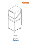
1
C 90
LO 50
Istruzioni per l'uso e la manutenzione
Instructions for use and maintenance
Mode d'emploi et entretien
Gebrauchs - und Wartungsanweisungen
Instrucciones para el uso y el mantenimiento
Ed. 10/2003
DICHIARAZIONE DI CONFORMITA’ - DECLARATION OF CONFORMITY
DECLARATION DE CONFORMITE - KONFORMITÄTS ERKLÄRUNG
C 90-LO 50
Noi - The undersigned- Nous soussignés - Die Unterzeichnete Fa:
HOONVED S.r.L.
via Ugo Foscolo, 1 - 21040 Venegono Superiore - (VA - ITALIA)
dichiariamo sotto la nostra esclusiva responsabilità che il prodotto
hereby declares under full responsability that the following product
attestons sous notre entière responsabilité que le produit suivant
erklärt unter eigener Verantwortung, dass folgende Produkte
LAVAOGGETTI - LAVE OBJETS - UTENSIL WASHERS - SPÜLMASCHINE
(descrizione del prodotto - product description - description du produit - Produktbeschreibung)
C 90 -LO 50
(tipo modello - type model - type modèle - Typ Modell)
al quale questa dichiarazione si riferisce è conforme alle seguenti norme:
to which this declaration refers, is conform with the following standards:
auquel se référé cette dèclaration, est conforme aux normes suivantes:
auf welche sich diese Erklärung bezieht, folgendem Standard entsprechen:
EN 60335-1 (1988) + A2, A5, A6, A51, A52, A53, A54, A55.
Sicurezza degli apparecchi elettrici d’uso domestico e similare. Norme generali.
Safety of household and similar electrical appliances - General requirements.
EN 60335-2-58 (1993)
Sicurezza degli apparecchi elettrici d’uso domestico e similare. Parte 2°: Norme particolari lavastoviglie per uso collettivo.
Safety of machine - Basic concept general for design - Technical principles and specifications.
EN 55014 (1993)
Limiti e metodi di misura caratteristiche di radiodisturbo degli apparecchi elettrodom. , utensili portatili ed apparecchi elettrici simili.
Limits and methods of measurement of radio disturbance characteristic of motor-operated and thermal appliances for household
and similar purposes.
EN 55104 (1995)
Requisiti di immunità per apparecchi elettrodomestici, utensili e degli apparecchi elettrici similari.
Immunity requirement for household appliances, tools and similar apparatus and purposes.
in base a quanto prescritto dalle Direttive:
on the basis of what is foreseen by the Directives:
selon ce qui est prevu par les Directives:
aufgrund der vorgesehenen Richtlinien:
73/23/CEE, 93/68/CEE (LVD)
89/392/CEE, 92/368/CEE, 93/68/CEE (MACHINERY)
89/336/CEE, 92/31/CEE, 93/68/CEE (EMC)
Decliniamo ogni r esponsabilità per sinistri a persone o a cose derivanti da manomissioni da par te di ter zi o da carenze di manutenzione o riparazione.
We decline any r esponsability for injuries or damage derived from machine misuse, abuse by others or improper machine maintenance or repairs.
Nous déclinons toute responsabilité pour sinistres à personnes ou à objet qui derivent de l’invention de la par t de tiers non specialistes ou de
carences de manutention ou r eparation.
Wir lehnen jegliche Verantwortung für Schäden an Personen oder Dingen ab, die auf fehlerhaftes Eingr eifen Dritter oder auf mängelhafte Wartung
oder Reparation zurückzuführen sind.
2003
- Data emissione - date of issue - Date d’ emission - Ausgabedatum -
2
Consigliere D’Amministrazione
Joakim Granfors
C 90-LO 50
LAVASTOVIGLIE
DISHWASHING MACHINE
LAVE-VAISSELLE
GESCHIRRSPÜLER
LAVAVAJILLAS
Mod.
C 90
LO 50
○ ○ ○ ○ ○ ○ ○ ○ ○ ○ ○ ○ ○ ○ ○ ○ ○ ○ ○ ○ ○ ○ ○ ○ ○ ○ ○ ○ ○
○ ○ ○ ○ ○ ○ ○ ○ ○ ○ ○ ○ ○ ○ ○ ○ ○ ○ ○ ○ ○ ○ ○ ○ ○ ○ ○ ○ ○
Le figure relative alle istruzioni sono riportate sulle ultime
pagine.
The illustrations concerning these instructions are on the
inside of the back cover
Les figures concernant les notices d'utilisation sont groupées
sur les dernières pages.
Die Bilder zur Gebrauchsanweisung sind auf den letzten
Seiten des Umschlages.
Las figuras correspondientes a las instrucciones se
encuentran en las ùltimas paginas.
Realizzato da HOONVED srl (VA) U.T.- Tel. 0331-856111
- cod. 34456 - Ed.10/03 - www.hoonved.com
3
C 90-LO 50
ITA
AVVERTENZA
Prima di procedere all'installazione, alla messa in funzione, alla regolazione e alle operazioni di manutenzione della lavastoviglie
Mod. C 90-LO 50, leggere attentamente il presente manuale.
In caso di guasto o cattivo funzionamento della macchina rivolgersi esclusivamente ad un centro tecnico autorizzato o direttamente
alla ditta HOONVED.
GBR
IMPORTANT
Become thoroughly familiar with the contents of thi manual before installing, setting up, adjusting and servicing diswasher machine
Mod. C 90-LO 50 .
Only contact an authorized technical center or HOONVED in the event of breakdowns or faulty machine operation.
FRA
IMPORTANT
Lisez attentivement cette notice avant la mise en place, la mise en service, le réglage et les opérations d’entretien de la machine
lave-vaisselle Mod. C 90 .
En cas de panne franche ou de dysfonctionnement de la machine, adressez-vous exclusivement à un service technique agréé
ou directement à la société HOONVED.
DEU
C 90HINWEIS
Bevor man den Geschirrspüler Mod. C 90-LO 50 installiert, in Betrieb nimmt, einstellt oder Wartungsarbeiten daran vornimmt,
ist dieses Handbuch aufmerksam durchzulesen.
Bei Störungen oder Fehlbetrieb der Maschine wenden Sie sich bitte ausschließlich an einen autorisierte Servicestelle oder direkt
an HOONVED.
SPA
ATENCION
Antes de realizar la instalación, la puesta en marcha, los ajustes y las operaciones de mantenimiento de la máquina lavavasos
Mod. C 90-LO 50, lea atentamente este manual.
En caso de avería o de mal funcionamiento se dirija exclusivamente a un centro técnico autorizado o directamente a la empresa
HOONVED.
4
C 90-LO 50
INDICE-INDEX
Avvertenza. ......................................................... pag. 4
Important
Important
Hinweis
Atencion
Dimensioni d'ingombro. .................................... pag. 6
Overall dimensions
Dimensions d'encombrement
Platzbedarfmasse
Dimensiónes
Dati tecnici. ......................................................... pag. 6
Technical data
Données techniques
Technischen daten
Nociones praticas
Descrizione comandi. ........................................ pag. 8
Decription of the controls
Description des commandes
Beschreibung der Bedienvorrichtungen
Descripcion de los mandos
ITALIANO. ........................................................... Pagina10
ENGLISH. ............................................................ Page 16
FRANÇAIS. .......................................................... Page 21
DEUTSCH. ........................................................... Seite 26
ESPAÑOL. ........................................................... Página 32
5
C 90-LO 50
C 90-LO 50
6
Resistenza boiler
Boiler heating element
Résistance chauffe-eau
Boilerheizwiderstand
Resistencia hervidor
Resistenza vasca
Tank heating element
Résistance cuve
Wannenheizwiderstand
Resistencia tina
Pompa lavaggio
Wash pump
Pompe de lavage
Spülpumpe
Bomba de lavado
7620 W
6000 W
3000 W
1620 W (2,2 Hp)
11620 W
10000 W
Consumo acqua per ciclo
Water consumption cycle
Consom; d’eau par cycle
Wasserverbr; pro Zyklus
Cons. agua por ciclo
Modello
Model
A
2÷ 4 bar. Ø 3/4"G.
4l
8,5 l
B
C
D
C 90 - LO 50 620 735 1230 1325
Dimensioni cestello
Basket dimensions
Dimensions du panier
Korbgröße
Dimensiones cubeta
A
Durata ciclo
Cycle lenght
Durée du cycle
Zyklusdauer
Duracíon del ciclo
Allacciamento elettrico
Electric supply
Raccordement électrique
Stromversorgung
Alimentacion electrica
Produzione cestelli/ora
Baskets output p/h
Débit paniers/h
Produktion korbe/stunde
Producción canastos/hora
Potenza totale
Total power
Puissance totale
Gesamtleistung
Enlace total
35 l
400V3 N~50Hz
230V3~50 Hz
230/240V1~50 Hz
440V3 ~60Hz
Alimentazione idrica
Mains supply of water
Alimentation en eau
Wasseranschluß
Alimentacíon idrica
30/15/10
Capacità boiler
Boiler capacity
Capacité du chauffe-eau
Boilerkapazität
Capacidad hervidor
Capacità vasca
Tank capacity
Capacité de la cuve
Wannenkapazität
Capacidad tina
DIMENSIONI DI INGOMBRO - OVERALL DIMENSIONS - DIMENSIONS D'ENCOMBREMENT
PLATZBEDARFSMASSE - DIMENSIÓNES
C 90-LO 50
D
E
F
G
B
E
F
G
500
540
145 ÷ 180
DATI TECNICI - TECHNICAL DATA - DONNÈE TECHNIQUES
TECHNISCHE DATEN - DATOS TECNICOS
3000W (60Hz) 1620 W(60Hz)
120/240/360 s
511 x 616 mm
C 90-LO 50
C 90-LO 50
Ø 31 mm
80° ÷ 90° C
Livello pressione acustica
Noise level
Niveau de pression sonore
Schalldruckpegel
Nivel de presion acustica
Temperatura risciacquo
Rinse temperature
Température de rinçage
Klarspültemperatur
Temperatura de aclarado
110 kg
5° ÷ 40° C
20 ÷ 90 %
Temperatura lavaggio
Wash temperature
Température de lavage
Spültemperatur
Temperatura de lavado
Umidità relativa
Environmetal humidity min/max
Humidité relative
Relative Feuchte
Humedad relativa
135 kg
Temperatura di funzionamento e stoccaggio
Environmetal temperature min/max.
Température de fonctionnement et stockage
Betriebs- und Lagertemperatur
Temperatura de funzionamento
Peso macchina imballata
Gross weight
Poids de la machine emballée
Gewicht der verpackten Maschine
Peso de la maquina embalada
Peso netto
Net weight
Poids net
Reingewicht
Peso netto
Raccordo di scarico
Drain pipe fitting
Raccord de vidange
Abwasseranschluß
Enlace de descarga
C 90-LO 50
50° ÷ 60° C
< 70 dB (A)
7
CRUSCOTTO COMANDI - CONTROL PANEL - PANNEAU DES COMMANDES
SCHALTBLENDE - PANEL DE MANDOS - PAINEL DE CONTROLE
C 90-LO
5
4
3
1
2
6
LEGENDA
1)
Selettore linea
2)
Lampada linea
3)
Lampada temperatura raggiunta
4)
Selettore tempi lavaggio
5)
Pulsante START/SCARICO
6)
Lampada ciclo
7)
Termometro vasca
KEY
1)
2)
3)
4)
5)
6)
7)
°C
50
Line selector
Mains warning light
Temperature reached warning light
Washing time selector
START/DRAIN button
Cycle light
Tank thermometer
LEGENDE
1) Sélecteur de ligne
2) Lampe de mise sous tension
3) Lampe de température
4) Sélecteur des temps de lavage
5) Bouton de marche/Vidange
6) Lampe de cycle
7) Thermomètre cuve
7
40
0 30
10 2
50
60
ZEICHENERKLÄRUNG
1) Wahlschalter Leitung
2) Kontrolleuchte Netz ein
3) Kontrolleuchte Temperatur erreicht
4) Wahlschalter Spülzeiten
5) START-taste/Entleeren
6) Kontrolleuchte Zyklus
7) Thermometer Behälter
LEYENDA
1) Selector línea
2) Piloto línea
3) Piloto temperatura alcanzada
4) Selector tiempos de lavado
5) Tecla START/DESAGÜE
6) Piloto ciclo
7) Termómetro tanque
ITA
•
•
•
8
DESCRIZIONE COMANDI
•
Selettore di linea (1)
Ruotato in posizione “ I ” ON abilita il funzionamento normale
della macchina; ruotato in posizione “ 0 ” OFF disabilita tutte
•
le funzioni della macchina.
Condizione di scarico in automatico (optional)
(solo su macchine con pompa di scarico)
•
Entra in funzione durante l' immisione dell'acqua di
risciacquo.
•
Condizione di scarico in manuale (optional)
Vedere pagina 13 punto 3.3.e.
Lampada linea (2)
Illuminata indica linea inserita.
Lampada Temperatura raggiunta (3)
Lampeggia mentre è attivo il riscaldamento dell'acqua
della vasca, si illumina fissa al raggiungimento della
stessa.
Selettore tempi lavaggio (4)
Ruotato nelle varie posizioni imposta il tempo di
lavaggio programmato.
Pulsante START (5)
Premuto, avvia il ciclo di lavaggio; la fine del ciclo
è indicata dallo spegnimento della lampada (6)
Lampada ciclo (6)
Illuminata indica il funzionamento del ciclo.
Termometro vasca (7)
Indica la temperatura dell'acqua contenuta nella
vasca di lavaggio.
C 90-LO 50
GBR
•
•
•
•
•
•
•
Line selector (1)
Turned on position “I” ON, this enables normal machine
operatio; turned to position “0” OFF, it disables all machine
functions.
Drain condition in automatic (optional)
(only on machines with drain pump)
It works only during rinsing water inlet.
Drain condition in manual (optional)
See page 19 point 3.3.e.
Mains warning light (2)
When on, indicates that the power source is connected.
“Temperature reached” warning light (3)
Flashed whilst the water in the tub is being heated.
Remains permanently on once the set temperature has
been reached.
Washing time selector (4)
Turned to the various positions, this is used to set the
programmed washing time.
Start /Drain button (5)
When pressed, this activates the normal washing cycle.
The light (6) goes out once the cycle ha s terminated.
Cycle light (6)
When on, indicates that the cycle is operating.
Tank thermometer (7)
Indicated the temperature of the water in the washing
tank.
DEU
•
•
•
•
•
•
•
FRA
DESCRIPTION OF CONTROLS
•
•
•
•
•
•
•
BESCHREIBUNG DER
BEDIENVORRICHTUNGEN
Wahlschalter Leitung (1)
Auf die Position “I” ON gedreht, wird der normale
Maschinenbetrieb freigegeben. Wenn der Wahlschalter
auf die Stellung “0” OFF gedreht wird, sind alle Funktionen
der Maschine gesperrt.
Automatische Ablauf (freigestellt)
(nur auf Maschine mit Ablaufpumpe)
Es lauft währed Nachspülwasser-einlaß.
Manuel Ablauf (freigestellt)
Sehen Seite 31 punkt 3.3.e.
Kontrolleuchte Netz ein (2
Leuchtet auf, wenn die Maschine ans Netz angeschlossen ist.
Kontrolleuchte Temperatur erreicht (3)
Blinkt auf, während das Wasser im Behälter aufgeheizt
wird, leuchtet mit Konstantlicht, wenn die vorgegebene
Temperatur erreicht ist.
Wahlschalter Spülzeiten (4)
Wenn man diesen Wahlschalter auf die verschiedenen
Stellungen dreht, erhält man die programmierte Spülzeit.
START-taste/Entleeren (5)
Zyklus wird durch das Verlöschen der Kontrolleuchte (6)
gemeldet.
Kontrolleuchte Zyklus (6)
Leuchtet auf, um anzuzeigen, daß der Zyklus abläuft.
Thermometer Behälter (7)
Zeigt die Temperatur des Wassers an, das im Spülbehälter
vorhanden ist.
Sélecteur de ligne (1)
Tourné sur la position “I” ON il valide le fonctionnement
normal de la machine; tourné sur la position “0” OFF il
exclut toutes les fonctions de la machine.
Condition de vidange en automatique (optional)
(seulement sur machines avec pompe de vidange)
Il entre en fonction pendant l'introduction de l'eau de
vidange.
Condition de vidange en manuel (optional)
Voir page 25 point 3.3.e.
Lampe de mise sous tension (2)
Indique la mise sous tension de la machine.
Lampe de température (3)
Clignotante pendant le chauffage de l’eau dans la cuve.
Allumée de manière fixe quand la température
programmée est obtenue.
Sélecteur des temps de lavage (4)
Tourné dans les différentes positions, il détermine la
durée de lavage programmée.
Bouton de marche/Vidange (5)
Enfoncé, il met en marche le cycle notmal de lavagé;
la fin du cycle est indique par le voyant (6) qui s'éteint.
Lampe de cycle (6)
Elle s’allume pour indiquer le cycle en cours d’exécution.
Thermomètre cuve (7)
Indique la température de l’eau contenue dans la cuve de
lavage.
ESP
•
•
•
•
•
•
•
DESCRIPTION DES COMMANDES
DESCRIPCION DE LOS MANDOS
Selector de línea (1)
Si se gira hacia la posición “I” ON se habilita el
funcionamiento normal de la máquina; por el contrario, si
se gira hacia la posición “0” OFF se deshabilitan todas las
funciones de la máquina.
Condicion de descarga en automatico (optiònal)
(solo en las maquinas con la bomba descarga)
Funciona durante la indroduccion de agua de aclarado.
Condicion de descarga en manual (optiònal)
Ver pàgina 37 punto 3.3.e.
Piloto línea (2)
Iluminada indica línea conectada.
Piloto Temperatura alcanzada (3)
Centellea mientras que se está calentando el agua en la
pila y la luz permanece fija cuando alcanza la temperatura.
Selector tiempos de lavado (4)
Si se gira en las distintas posiciones, se programa el
tiempo de lavado deseado.
Tecla START/DESAGÜE (5)
Presionada pone en marcha el ciclo normal de lavado;
cuando el indicador (6) se apague, sigificarà que el ciclo
ha finalizado.
Piloto ciclo (6)
Encendida, indica el funcionamiento del ciclo.
Termómetro tanque (7)
Indica la temperatura del agua que se halla en la pila de
lavado.
9
ENGLISH
PARTICULAR RECOMMENDATIONS
FOR THE OPERATOR
-
Do not operate the machine without having become fully
familiar with the contents of this manual and without having
acquired a comprehensive knowledge of the specific
techniques and machine controls.
-
Check that the area in which the machine is to be installed is
compatible with the dimensions of the machine itself before
installing this latter.
-
Only use lifting and handling means as are adequate to the
weight of the machine when this must be installed or removed
either completely or in part.
-
Never allow unauthorized or unqualified personnel to start,
adjust, operate or repair the machine. Always refer to this
manual for the necessary operations.
-
The mechanical parts and electrical/electronic components
situated inside the machine are protected by entirely closed
panels.
-
Always ensure that the main switch has been set to the
“OFF” position before cleaning and/or servicing the machine
and before removing any guard. This will disconnect the
power source during the operator’s intervention.
-
The electrical powering system must be equipped with an
automatic release system prior to the main machine switch
and with a suitable grounding system that complies with all
the requisites established by industrial provisions for the
prevention of accidents.
-
Always disconnect the power source if work must be carried
out on the main switch or in its vicinity.
-
All inspections and maintenance operations requiring removal
of the safety guards are carried out under the complete
responsibility of the users.
These operations should therefore only be carried out by
specialized and authorized technical personnel.
-
Check that none of the accident preventing safety devices
(barriers, guards, casings, microswitches, etc.) have been
tampered with and that they are all perfectly functional before
operating. These devices should be repaired if this is not the
case.
-
Never remove the safety devices.
-
To prevent personal risks, only use power tools that are
correctly connected to the grounding tap and that conform to
the national safety regulations.
-
Never ever tamper with the electrical system or with any other
mechanism.
-
Never ever use the hands or unsuitable instruments to
locate leaks from pipes. Air, fluids under pressure or irritants
could cause serious damage to both persons and/or property.
-
Never use the hands instead of adequate tools when operating
the machine.
16
C 90-LO 50
-
Never use the hands or other objects to stop moving parts.
-
PAY THE UTMOST ATTENTION TO THE DATA PLATES
AFFIXED TO THE MACHINE WHENEVER WORKING ON
THIS OR ON THEIR NEAR VICINITY.
-
The user is obliged to keep all the data plates and stickers in
a legible condition.
-
It is essential for the user to replace all data plates and
stickers as may have deteriorated for any reason or as are not
clearly visible, ordering new ones from the Spares Service of
HOONVED.
-
Contact the person in charge of maintenance in the event of
malfunctions or damage to the machine components without
proceeding with further repairs.
-
It is absolutely forbidden for anyone to use the machine for
purposes other than those explicitly established and
documented. The machine must always be used in the ways,
times and places established by common sense, the laws in
force in each nation, even when there are no specific provisions
to govern the sector in the specific country of use.
-
HOONVED declines all responsibility for accidents or
damage to either persons or propertry as may arise
following failure to comply with either the relative safety
provisions or the instructions herein.
-
These instructions, together with the provisions
governing machine installation and electrical
connections form an integral part of the Accident
Preventing Industrial regulations in force in each
individual country.
-
THESE SAFETY PROVISIONS INTEGRATE AND DO NOT
SUBSTITUTE THE SAFETY PROVISIONS LOCALLY IN
FORCE.
-
NEVER ever make hurried or inaccurate repairs as could
jeopardize the correct operation of the machine.
-
ALWAYS ASK FOR HELP FROM SPECIALIZED
PERSONNEL IN CASE OF DOUBT.
-
ANY TAMPERING BY THE USER RELIEVES THE
MANUFACTURER FROM ALL LIABILITY, THE USER
BEING IN THIS CASE SOLELY RESPONSIBLE TOWARDS
THE COMPETENT ACCIDENT PREVENTION
AUTHORITIES.
ENGLISH
C 90-LO 50
1.1 GENERAL DESCRIPTION
The dishwasher of the C 90/LO 50 give an excellent idea
of the know-how achieved by Hoonved in the field of
machines for catering sector.
1.2 TYPE OF USE AND IMPROPER USE
These machines have been designed and built to wash
object in special baskets and using detergent and rinsing
agent.
• Use of specific detergents and rinsing agents for
industrial purposes normally available in the shops is
permitted.
ATTENTION
Any improper use of the machine relieves the manufacturer
from all and every responsibility for accidents or damage
to persons and property, also voiding all conditions of
guarantee.
1.3 TRANSPORT, SHIPMENT AND
STORAGE (Fig. 2)
-
The machine is normally shipped in a cardboard box
closed by straps.
When transporting the packed machine, use a lift truck
or transpallet, positioning the box on the relative forks.
ATTENTION
The machine must be sheltered from the weather when
shipped and stored.
structure, crushing or breakages.
If damage or imperfections are discovered:
1 - Immediately notify the haulage contractor both by
phone and in writing by registered letter with return
receipt attached;
2 - Inform the manufacturer by registered letter (with return
receipt attached).
IMPORTANT
Norification of damage or faults must be immediate, in any
case within 3 days from the date on which the machine is
received.
1.5 UNPACKING (Figs 2-3-)
Proceed in the following way in order to remove the
packing:
1. Cut the straps (7) that hold the cardboard in place.
2. Remove the box (8) by lifting it upwards.
3. Remove the protective film from the machine.
4. Remove the machine from the base by lifting it from the
lower part of the casing.
5. All packing must be collected and not left within children’s
reach since it could become a source of danger. The
packing can be disposed of in the same way as solid
urban waste.
Lift the machine by raising the lower part of the casing
using a lift truck or transpallet.
1.6 MACHINE IDENTIFICATION (Fig. 4)
-
ATTENTION
Before installing the machine, control the rotation
way of the motor (Fig. A).
The serial number and machine data are stamped on
the data plate (9) affixed to the rear part of the machine
itself.
IMPORTANT
Always state the model and serial number of the machine
when requesting technical assistance or ordering spare
parts.
1.7 DESCRIPTION OF THE SAFETY
DEVICES
•
Fig.A
1.4 INSPECTIONS ON ARRIVAL
When the machine arrives, check that the packaging is in
a perfect condition and that there is no visible damage.
If everything is in order, remove the packaging (unless
other instructions have been received from the
manufacturer) and check that the machine is free from
damage caused by transport.
Now check whether there has been any damage to the
•
•
•
Models C 90/LO 50 are equipped with a safety
microswitch that blocks the washing pump if the tub
access door is accidentally opened, and of other
electronic safety devices.
The electrical parts are enclosed by panels locked by
screws.
The machine is fitted with an equipotential ground
conductor ( 10 Fig. 6).
Safety overflow to prevent water from spilling.
1.8 REFERENCE STANDARD
•
•
The machine and its safety devices has been built in
compliance with the following standards:
Essential safety requisites pursuant to Directive 73/23
EEC Annex 1 modified by Directive 93/68 EEC,
Directive 89/336 CEE, 89/392/CEE, 92/368/CEE,93/
68/CEE.
17
ENGLISH
C 90-LO 50
Part3:
3:
Part
For
the
technicianand
andoperator
operator
For the technician
Part 2:
For the qualified technician
2.1 INSTALLATION (Fig. 5)
-
-
After having removed the packing, check that the
machine is in a perfect condition and that all the parts
have been included.
Position the machine in the required setting and level
it by means of the feet (11).
2.1.a Drain pipe connection (Fig. 5)
- Connect one end of the drain pipe to the overflow
(12) and the other to an already prepared drain trap.
IMPORTANT
It is essential to ensure that the drain pipe runs along the
floor and that it is not throttled in any part.
2.1.b Connection to the water main (Figs. 5-6)
- Connect one end of the supplied inlet pipe (13) to the
solenoid valve (14) and the other end (13) to a 3/4” G
threaded cock, installing the filter (15 Fig. 6) in between.
3.1 DETERGENT DISPENSER (Optional)
(Fig. 7)
The machine is equipped with an automatic detergent
dispenser.
• Insert the red supply tube (17) into the cannister
(18).
ATTENTION
Always wash the hands under running water if they come
into contact with detergent, or comply with the specific
indications pertaining to the utilized type of detergent.
• Proceed with a few no-load cycles until the intake and
delivery tubes have filled.
To adjust the dispenser, refer to the relative enclosed
manual and to the utilized type of detergent.
3.2
•
ATTENTION
It is essential to connect the cold water delivery pipe to a
throttle cock in order to separate the water main from the
machine itself. Also check that there are no sharp bends.
If there is sand in the water main, it will be necessary to
install a filter between the water main and the machine. If
the water main is without, it is advisable to install a
decalcifier prior to the machine with a setting of min. 4 and
max. 8 French degrees.
The manufacturer declines all responsibility for
damage to the machines caused by failure to comply
with the above listed provisions.
2.1.c Electrical connection (Fig. 5-6)
-
-
-
•
•
18
DANGER
Before connecting to the electricity main, always
check that the data pertaining to the power source
correspond to those indicated on the identification
plate ( 9 Fig. 4) and that the main electric power
switch installed prior to the machine is
disconnected “0” OFF.
An appropriately sized omnipolar circuit-breaker
with a minimum 3 mm gap between its contacts
must be installed between the power supply main
and the machine.
The manufacturer declines all responsibility for
accidents or damage to persons or property caused
by failure to comply with the above listed provisions.
Connect the electrical power cable (16) to the main
switch installed prior to the machine.
Connect the equipotential ground conductor to the
terminal (10).
•
•
FILLING THE RINSING AGENT DISENSER
(Fig. 7)
Insert the transparent tube (19) into the cannister (20)
containing rinsing agent.(Refer to the specific
instructions given with the rinsing agent itself).
Start the machine as described in paragraph 3.3. The
dispenser will suck about 3 cm of liquid from the
cannister.
Fill during the cycle by opening (slightly) and closing
the door until the tube has completely filled.
3.2.a Adjusting the dose (Fig. 7)
• Start the machine as described in paragraph 3.3 amd
hold a glass up to the light at the end of the cycle.
• The drops of water on the glass will indicate insufficient
dosage while, the streaking or spotting will indicate,
instead, an excessive dosage.
• Regulate by means of the plug (21), turning clockwise
to decrease the quantity or anticlockwise to increase it.
IMPORTANT
These data are indicative and not binding since they may
vary according to the hardness of the water or the utilized
type of detergent and rinsing agent.
ATTENTION
If the utilized product (detergent or rinsing agent) is
changed, it is advisable to flush out the dosing system with
water and to then proceed by filling the dispensers.
3.3 PREPARING THE MACHINE AND THE
WASHING OPERATIONS
3.3.a Preparing the machine (Fig. 8)
1. Turn on the main power switch prior to the machine.
2. Open the water supply cock.
3. Check that the cannister of detergent (Optional) and
rinsing agent contain sufficient product for daily needs.
ENGLISH
C 90-LO 50
4. Turn the mains selector (1) and the lamp (2) lights. The
washing tub will immediately begin to fill. Once the
correct level has been reached, the water will
automatically begin to heat. This is indicated by a
flashing light (3). Wait until the preset temperature has
been reached and the light (3) becomes fixed.
The machine will be ready to start the washing cycle
when the temperature in the tank (indicated by
thermometer 7 Fig. 1 on the panel ) reaches at least
50°C.
5. Open the door and pour the quantity of detergent
indicated by the manufacturer directly into the tub. This
operation need not be carried out when the machine is
equipped with the optional dispenser.
6. Choose the cycle length by means of the selector (4).
3.3.b Washing operations (Fig 8)
1. Load the dirty crockery into the basket (as indicated in
Fig. 10).
2. Press the START button (5), and the washing and
rinsing cycle will automatically begin and the warning
light (6) will come on.
3. The light (6) will go out to indicate that the cycle has
terminated. Now open the door and remove the basket.
4. Add a half of coffee cup of detergent after every 5/6
washes. This operation need not be carried out if the
machine is equipped with the optional dispenser.
The doses are indicative and not binding since they
vary according to the hardness of the water and utilized
type of detergent.
3.3.c Changing the water (Fig. 9)
This operation must be carried out after every 10 cycles or
so, according to the amount of accumulated dirt.
1. Remove the tub filters (22).
2. Switch off the machine as indicated in paragraph 3.3.d,
then lift the overflow (23) and allow the tub to completely
drain.
3. Refit the overflow (23) and the filters (22) in its housing
and repeat the machine preparation operations as
indicated in paragraph 3.3.a.
Repeat the doove mentioned operations till when the tank
is completely empty.
3.3.f Alarms (Fig. 8)
The machine will set to the alarm status in the following
cases:
• Tub refilling timeout.
If tank filling fails to terminate within 20 minutes, the
machine will set to the alarm status. This is indicated by
fast flashing warning light (6). Switch off the machine
by turning selector (1) to 0 “OFF” to reset the alarm.
• No water in the tub.
When the safety level probe detects insufficient water,
the function in progress will abort, the tub and boiler
heating function will be inhibited and the machine will
set to the alarm status. This is indicated by fast flashing
warning light (6). Switch off the machine by turning
selector (1) to 0 “OFF” to reset the alarm.
• Overheating.
If the temperature of the water in the boiler or tub
exceeds 98°C, the machine will set to the alarm status,
inhibiting all functions and any cycle in progress. The
alarm status is indicated by fast flashing warning light
(3).
The alarm automatically disactivates when the temperature drops below 90°C. Failing this, switch off the
machine by turning selector (1) to 0 “OFF” to reset.
• Heating timeout.
The machine will set to the alarm status if, after 20
minutes continuous boiler heating, the temperature
remains less than 45°C. This is indicated by fast
flashing warning light (3).
Switch off the machine by turning selector (1) to 0
“OFF” to reset.
ATTENTION
Contact the after-sales service center if the alarm
continuously activates.
3.3.d Switch-off (Fig. 9)
At the end of the work day, set the line switch (1) to position
“0” OFF, discomnnect the main switch installed prior to the
machine and turn off the water delivery cock.
ATTENTION
Disconnect the main circuit-breaker prior to the machine
and turn off the water delivery cocks if the dishwasher is
faulty or operates badly.
Only allow the manufacturer’s authorized after-sales
service center to make repairs.
3.3.e Manual drain timering (Fig. 1)
(on machine with drain pump only)
To manually empty the water from the tub, switch off the
line button (6) Fig. 1 and push the START/DRAIN button
(1) for a determinated time.
19
ENGLISH
C 90-LO 50
4. CLEANING (Fig. 9)
4.1 General information
Strict compliance with the maintenance instructions in this
section will keep your machine in a good working condition
and will notably reduce the need for repairs.
ATTENTION
If any machine component becomes faulty, FIRST CHECK
that all the instructions given in the previous paragraphs
have been complied with during use.
Repairs must be carried out immediately, as soon as the
fault occurs. This will prevent the trouble from becoming
worse and damaging other parts.
4.2 Daily cleaning (Fig. 9)
ATTENTION
Daily operations to carry out when work has ended, with
the machine off, the main circuit-breaker disconnected,
the water cocks off and the washing tub empty.
1. Remove the filters (22) on top of the tube.
2. Lift the overflow pipe (23) to completely drain the water
from the tub.
3. Thoroughly clean the inside parts of the machine.
4. Remove the pump safety filter (24).
5. Wash the filters under running water and fit them
correctly back in their housings.
6.
DESCALING
Where hard water is present lime scale deposits will
form in the machine and on dishes, which must, for
reasons of hygiene, be removed by descaling.
Advice on operation procedures and frequency for this
treatment are generally given by the detergent supplier,
who can provide suitable products.
In order to avoid damaging the machine, do not
exceed recommended doses, follow the detergent
producer’s directions scrupulously and, having
finished operations, rinse thoroughly
7.
TEMPORARY STOPPAGE
If the machine is to be left inactive for a period of some
weeks, it is advisable beforehand to load the tank and
run a few empty cycles with clean water then drain, so
as to avoid the formation of unpleasant odours.
If necessary, repeat the process several times until the
water is still clean after washing.
If the stoppage is to be very long, it is advisable to
drain the water from the boiler and from the electric
pump.
8.
DEMOLITION and DISPOSAL.
ATTENTION
Never ever clean the outside parts of the machine with jets
of water.
Never use corrosive or acid cleaning products, wire wool
or steel brushes since these could damage the machine.
5. PREVENTION MAINTENANCE (Fig. 9)
ATTENTION
The preventive maintenance operations must be carried
out with the machine off, the main circuit-breaker
disconnected, the water delivery cocks off and the washing
tub empty.
5.1 Checking and cleaning the spray arms and
nozzles
(Fig. 9)
Periodically check to make sure that the spray arm (25),
the rinsing arm (26) and the relative nozzles are not
clogged.
Cleaning the unit:
1. Unscrew the ring nut (27) and lift the spray arms (25)
and (26).
2. Wash the washing and rinsing spray arms.
Clean the nozzles if they are clogged and then fit the
parts exactly back in their original positions.
3. Remount all parts by complying with the above
instructions in reverse.
20
When the machine is to be scrapped, drain the water
from the tank and from the boiler, as indicated in the
points above, and disconnect the machine from the
water and electricity supply networks, then dispose of
the components according to current regulations,
respecting national and local ecological and
environmental legislation, and taking care to separate
the parts as follows:
- metallic parts: body work, surfaces, panels, filters;
- electrical parts: motors, remote switches, microswitches, cabling;
- plastic parts: connectors, baskets;
- rubber parts: tubes, couplings
The producer declines all responsibility for any
printing errors contained in this booklet.
The instructions, drawings, tables and everything
else in this manual are of a confidential technical
nature. For this reason, none of the information may
be either completely or partially duplicated or disclosed
to third parties without prior written authorization
from HOONVED which is the sole proprietor and
which reserves the right to make any modifications as
may be considered necessary without advance
warning.
ENGLISH
C 90-LO 50
TROUBLESHOOTING
PROBLEMS
CAUSES
SOLUTIONS
The machine fails to turn on.
Main switch disconnected.
Turn on the switch.
The machine does not fill with
water.
Water cock shut.
Dirty fill pipe filter.
Turn on the clock.
Detach the fill pipe (13 Fig. 6) and clean the filter
(15).
Unscrew and clean the nozzles (A Fig. 9) under
running water.
Check the right connection of the overflow pipe (23
Fig. 9)
Rinsing nozzle clogged.
Overflow pipe not well
connected.
Insufficient washing.
Wrong pump rotation direction.
Clogged washing nozzles.
Dirty washing filter.
Clogged washing blade.
No detergent.
Machine not in temperature
(Green light (3) Fig. 8)
Insufficient rinse.
Call the technician to reverse 2 of the 3 wires on
the main switch.
Clean the washing blade (25 Fig. 9).
Clean the filters (22 e 24 Fig. 9).
Remove and clean the balde (25 Fig. 9)
Add detergent and fill the dispenser.
Wait the green fixed light (3) Fig. 8.
Clogged boiler by limestone.
Low main pressure
(less than 2 bar. - 200 Kpa).
Check the correct washing phase.
Unscrew and clean the nozzles (A Fig. 9) under
running water.
Call after-sales service.
Wait pressure recovery or purchase a new
pressure pump.
Insufficient temperature.
Bad location of the nozzles or
damaged nozzles.
Call after-sales service.
Check the right location of the nozzles and replace
damaged ones.
Insufficient washing conditions.
Clogged rinsing nozzles.
21
La ditta costruttrice si riserva il diritto di apportare
modifiche che si renderanno utili ai propri prodotti
senza comprometterne le caratteristiche essenziali.
The manufacturer reserves the right to modify its
products,whenever necessary ,without affecting their
main features.
Le constructeur se réserve le droit de modifier ses
produits sans en compromettre les caractéristiques
essentielles.
Der Hersteller behält sich das Recht vor , seine Produkte abzüandern , falls es notwendig sei , ohne die
haupteigenschaften des Gerät zu wechseln.
La Firma constructora se reserva el derecho de modificar sus productos sin comprometerne las caracteristicas esenciales.
40
15
16
18
17
13
+
19
21
10
20
Fig. 7
Fig. 6
5
24
3
1
6
4
2
Fig. 8
23
26
A
22
25
27
A
Fig. 9
42
MARRONE /BROWN
C1
NERO / BLACK
VIOLA /VIOLET
ROSSO / RED (Mod. C 90 )
MARRONE / BROWN (Mod.ED 650 )
DD
DD
LC LL
ROSSO/RED
LB LD
BIANCO / WHITE
ARANCIO / ORANGE
ROSSO / RED
*solo per modelli previsti di PP
only for model with PP
PS
GRIGIO/GREY
BLU/BLUE
BIANCO ROSSO /WHITE RED
C2
NERO / BLACK
SL
1
VASCA
TANK
BOILER
PROBE
TEMP.
SONDA
TEMP.
BOILER
C 90-LO 50
400V3N - 50/60 HZ
230V3 - 50/60 HZ
ED 650 E/S - C 90
solo per macchine con Start con tasto
only for machine with Start by push button
LIV. SIC.
TANK
PROBE
TEMP.
Ed. 10/2003
SCHEMA ELETTRICO- ELECTRIC DIAGRAM
VIOLA / VIOLET
C4
ROSSO/NERO - RED/BLACK
2
BIANCO/NERO - WHITE/BLACK
C3
AZZURRO / BLUE
NERO / BLACK
LMP
MARRONE / BROWN
3
MP1
PLD
PLB
SONDA
TEMP.
VASCA
Durata Risciacquo
Rinsing time
CN 3
4 3 2 1
10 9 8 7 6 5 4 3 2 1
Quantity of
Detergent
Boiler
Temperature
Tank
Temperature
Temperatura
Boiler
BIANCO/WHITE
DD
P5
Not connection link = wait boiler temperatur
fuse (32 mA)
Dose
Detersivo
NERO /BLACK
FS
0,5A
P3
Ponticello non inserito = attesa temper. boiler
Selezione tempi lavaggio
Washing time selection
P2
IL
ST1
BIANCO/ROSSO
P4
Selezione tempi lavaggio
Washing time selection
P1
Movable link
Selezione tempi lavaggio
Washing time selection
+
senso della regolazione
direction of regolation
N
L1
PE
Temperatura
CN 4 Vasca
CN 1
BIANCO / WHITE
MARRONE / BROWN
EV1
MARRONE /BROWN
Ponticelli mobili
12 11 10 9 8 7 6 5 4 3 2 1
CN 5
WHITE/RED
TPL
54321
P
FA1
NERO /BLACK
C6
*
TS
MP2
SCHEDA ELETTRONICA
PRINTED CIRCUIT BOARD
CN 2
1 2 3 4 5 6 7 8
FS 2,5A
AZZURRO / BLUE
470 ohm
230 V~50/60 Hz
= Filtro Antidisturbo - Electromagnetic Field Filter
= Pulsante Reset - Push Botton Reset
PR
= Interruttore linea - ON/OFF button
= Termostato sicurezza boiler - Boiler Safety thermostat
TS
= Lampada Mancanza Detersivo (solo ED 650) - Lamp Missing Detergent(only ED 650)
LD
= Fusibile - Fuse
= Lampada linea - Line lamp
LL
FS
= Lampada Ciclo - Cycle Lamp
LC
Pompa scarico
Drain pump
110 W
PS
4
2
PP
3
1
Pompa pressione
Pression pump
600 W
C6
N
L1
PE
N
4
2
6
5
6
5
Resistenza boiler
Boiler heating element
6000 W
RB
3
4
3
1
2
1
C2
2
1
L1
2
1
2
1
RV
4
3
RB
C3
C4
L2
RB
4
4
3
3
6
5
RB
6
5
6
5
FR
PE
4
RV
2
RV
TPL
6
5
MPL
4
3
230 V3 ~ 50Hz
MPL
3~
4
3
6
5
Pompa lavaggio
Wash pump
1100 W (ED 650 S)
900 W (ED 650 E)
1620 W - 2,2 Hp (C 90)
2
1
* TPL
RV
1
2
C1
6
5
C1
3
1
C2
230 V3~ 50 Hz
L1
L2
L3
Resistenza vasca
Tank heating element
3000 W
230 V~ 50 Hz
* solo per modelli ED 650
only for ED 650 model
C3
C4
400V3N~50Hz
L1
L2
L3
FA
Ed.10/03
*
LMP = Lampada Macchina Pronta - Lamp Ready Machine
= Lampada Mancanza Brillantante (solo ED 650) - Lamp Missing Rinside (only ED 650)
LB
PLD = Pressostato lampada detergente - Detergent lamp pressure switch
PLB = Pressostato lampada brillantante - Rinside lamp pressure switch
= Selettore tempi lavaggio - Washing time selector switch
SL
ST 1 = Start - Start
(solo x macchine con Start con tasto - only for machine with Start by push button)
IL
= Predisposizione doppio Microinterr. porta - Predisposition doubler Door microswitch
MP2
= Dosatore Detersivo - Detergent Pump
DD
= Microinterruttore porta - Door microswitch
= Pompa Scarico - Drain Pump
PS
400V3N - 50/60HZ
230V3 - 50/60 HZ
MP1
= Pompa Pressione - Pump Pression
PP
= Elettrovalvola - Electrovalve
= Resistenza vasca - Tank heating element
RV
EV1
= Resistenza Boiler - Boiler heating element
RB
MPL = Motore Pompa Lavaggio - Wash Pump
TPL = Termica pompa lavaggio - Wash pump thermal
C6 = Teleruttore pompa pressione - Remote Switch for pression pump
C4 = Teleruttore sicurezza - Safety Remote Switch
C3 = Teleruttore Boiler - Remote Control Switch for Boiler
C2 = Teleruttore Vasca - Remote Control Switch for Tank
C1 = Teleruttore pompa lavaggio - Remote Switch for wash pump
FA
LEGENDA - LEGEND
230V~50Hz
SCHEMA DI POTENZA / DIAGRAM POWER ED 650 E/S - C 90
C 90-LO 50
43
NERO / BLACK
VIOLA /VIOLET
ROSSO / RED (Mod. C 90 )
MARRONE / BROWN (Mod.ED 650 )
LC LL
ROSSO/RED
LB LD
BIANCO / WHITE
DD
DD
ARANCIO / ORANGE
ROSSO / RED
*solo per modelli previsti di PP e/o PS
only for model with PP e/o PS
C1
MARRONE /BROWN
C5
GRIGIO/GREY
VASCA
TANK
400V3 50/60 HZ
ED 650 E/S - C 90 440V3 50/60HZ
Ed.10/03
BOILER
PROBE
TEMP.
SONDA
TEMP.
BOILER
C 90-LO 50
solo per macchine con Start con tasto
only for machine with Start by push button
LIV. SIC.
TANK
PROBE
TEMP.
SONDA
TEMP.
VASCA
SCHEMA ELETTRICO- ELECTRIC DIAGRAM
VIOLA / VIOLET
BLU/BLUE
BIANCO ROSSO /WHITE RED
C2
NERO / BLACK
SL
1
BIANCO/NERO - WHITE/BLACK
C4
ROSSO/NERO - RED/BLACK
2
PLB
BIANCO/WHITE
C3
AZZURRO / BLUE
NERO / BLACK
LMP
MARRONE / BROWN
3
PLD
NERO /BLACK
DD
P5
Not connection link = wait boiler temperatur
MP1
MARRONE / BROWN
FS
0,5A
Selezione tempi lavaggio
Washing time selection
P3
Ponticello non inserito = attesa temper. boiler
Selezione tempi lavaggio
Washing time selection
P2
BIANCO/ROSSO
IL
ST1
BIANCO / WHITE
P4
Selezione tempi lavaggio
Washing time selection
Movable link
Durata Risciacquo
Rinsing time
CN 3
4 3 2 1
10 9 8 7 6 5 4 3 2 1
Quantity of
Detergent
Boiler
Temperature
Tank
Temperature
Temperatura
Boiler
Dose
Detersivo
fuse (32 mA)
L2
L1
PE
Temperatura
CN 4 Vasca
NERO /BLACK
EV1
*
MARRONE /BROWN
P1
Ponticelli mobili
12 11 10 9 8 7 6 5 4 3 2 1
CN 5
+
CN 1
senso della regolazione
direction of regolation
WHITE/RED
TPL
54321
P
FA1
AZZURRO / BLUE
C6
*
TS
MP2
SCHEDA ELETTRONICA
PRINTED CIRCUIT BOARD
CN 2
TRF
100VA
0
230V~
1 2 3 4 5 6 7 8
FS 2,5A
F 2A
0
44
440V~
400V~
470 ohm
400/440 V~50/60 Hz
- Electromagnetic Field Filter
Ed. 10/2003
400V~50Hz
440V~60Hz
= Resistenza vasca - Tank heating element
= Pulsante Reset - Push Botton Reset
RV
PR
Scarico - Drain Pump
= Pressostato lampada detergente - Detergent lamp pressure
= Lampada Mancanza Brillantante - Lamp Missing Rinside
= Lampada Mancanza Detersivo - Lamp Missing Detergent
PLD
LB
LD
= Fusibile - Fuse
F
Bobina teleruttore Pompa - Pump control switch spool
=
= Trasformatore - Transformer
TRF
BTS
BTP
= Termostato sicurezza boiler - Boiler safety termostat
= Bobina teleruttore sicurezza boiler - Boiler safety spool
TS
= Interruttore Linea - ON/OFF Button
= Micro Interruttore Porta - Door Microswitch
= Starter - Starter
ST
MP
= Lampada linea - Line lamp
LL
IL
= Lampada Ciclo - Cycle Lamp
LC
2
1
RB
4
3
4
3
6
5
6
5
Resistenza boiler
Boiler heating element
6000/10000 W
C3
2
1
L2
C2
L3
RV
4
3
6
5
TPL
C1
Resistenza vasca
Tank heating element
3000 W
2
1
PE
* solo per modelli ED 650
only for ED 650 model
FA
C4
L1
440V3~60 Hz
400V3~50 Hz
*
LMP = Lampada Macchina Pronta - Lamp Ready Machine
= Selettore durata lavaggio - Washing time selector switch
= Pressostato lampada brillantante - Rinside lamp pressure
Pompa Detersivo - Detergent Pump
Pompa
PLB
=
PD
SL
=
PS
EV1 = Elettrovalvola - Electrovalve
= Resistenza Boiler - Boiler heating element
RB
MPL= Motore Pompa Lavaggio - Wash Pump
TP1= Termica pompa lavaggio - Wash pump thermal
L2
L1
PE
C6 = Teleruttore pompa pressione - Rem. Switch for pression pump
C5 = Teleruttore pompa scarico - Remote Switch for drain pump
C4 = Teleruttore sicurezza - Safety Remote Control Switch
C3 = Teleruttore Boiler - Remote Control Switch for Boiler
C2 = Teleruttore Vasca - Remote Control Switch for Tank
C1 = Teleruttore pompa lavaggio - Remote Switch for wash pump
FA = Filtro Antidisturbo
LEGENDA - LEGEND
SCHEMA DI POTENZA / DIAGRAM POWER
ED 650 E /S - C 90 - 440V3 50/60HZ
400V3 50/60 HZ
MPL
4
3
6
5
C5
Pompa lavaggio
Wash pump
1100 W (ED 650 S)
900 W (ED 650 E)
1620 W - 2,2 Hp(C 90)
2
1
PS
4
3
Pompa scarico
Drain pump
110 W
2
1
6
5
C6
PP
4
3
Pompa pressione
Pression pump
600 W
2
1
C 90-LO 50
45
6
5
46
ROSSO / RED
BIANCO ROSSO /WHITE RED
C2
NERO / BLACK
MARRONE /BROWN
NERO / BLACK
BIANCO / WHITE
LC LL
ROSSO/RED
LB LD
ARANCIO / ORANGE
ROSSO / RED
DD
DD
GRIGIO/GREY
C4
ROSSO/NERO - RED/BLACK
2
SL
1
VASCA
TANK
BOILER
PROBE
TEMP.
SONDA
TEMP.
BOILER
C 90-LO 50
solo per macchine con Start con tasto
only for machine with Start by push button
LIV. SIC.
TANK
PROBE
TEMP.
C 90 240V/1/50 HZ
Ed.10/2003
SCHEMA ELETTRICO- ELECTRIC DIAGRAM
VIOLA / VIOLET
C1
AZZURRO / BLUE
NERO / BLACK
LMP
MARRONE / BROWN
3
BIANCO/NERO - WHITE/BLACK
DD
P5
Not connection link = wait boiler temperatur
MP1
PLD
PLB
SONDA
TEMP.
VASCA
Durata Risciacquo
Rinsing time
CN 3
4 3 2 1
10 9 8 7 6 5 4 3 2 1
Quantity of
Detergent
Boiler
Temperature
Tank
Temperature
Temperatura
Boiler
BIANCO/WHITE
FS
0,5A
Selezione tempi lavaggio
Washing time selection
P3
fuse (32 mA)
Dose
Detersivo
NERO /BLACK
BLU/BLUE
VIOLA /VIOLET
Ponticello non inserito = attesa temper. boiler
Selezione tempi lavaggio
Washing time selection
P2
IL
ST1
BIANCO/ROSSO
P4
Selezione tempi lavaggio
Washing time selection
Movable link
+
senso della regolazione
direction of regolation
N
L1
PE
Temperatura
CN 4 Vasca
CN 1
BIANCO / WHITE
MARRONE / BROWN
C3
MARRONE /BROWN
P1
Ponticelli mobili
CN 5
12 11 10 9 8 7 6 5 4 3 2 1
WHITE/RED
TPL
54321
P
FA1
NERO /BLACK
EV1
TS
MP2
SCHEDA ELETTRONICA
PRINTED CIRCUIT BOARD
CN 2
1 2 3 4 5 6 7 8
FS 2,5A
AZZURRO / BLUE
470 ohm
230 V~50 Hz
= Filtro Antidisturbo - Electromagnetic Field Filter
= Pulsante Reset - Push Botton Reset
PR
= Microinterruttore porta - Door microswitch
= Interruttore linea - ON/OFF button
= Start - Start
= Selettore durata lavaggio - Washing time selector switch
= Termostato sicurezza boiler - Boiler Safety thermostat
MP
IL
ST
SL
TS
= Lampada Mancanza Detersivo - Lamp Missing Detergent
LD
= Lampada Ciclo - Cycle Lamp
= Lampada linea - Line lamp
LC
LL
LMP = Lampada Macchina Pronta - Lamp Ready Machine
= Lampada Mancanza Brillantante - Lamp Missing Rinside
LB
PLD = Pressostato lampada detergente - Detergent lamp pressure switch
PLB = Pressostato lampada brillantante - Rinside lamp pressure switch
= Pompa Detersivo - Detergent Pump
PD
= Elettrovalvola - Electrovalve
= Resistenza vasca - Tank heating element
RV
EV1
= Resistenza Boiler - Boiler heating element
RB
MPL = Motore Pompa Lavaggio - Wash Pump
C4 = Teleruttore sicurezza - Safety Remote Control Switch
C3 = Teleruttore Boiler - Remote Control Switch for Boiler
C2 = Teleruttore Vasca - Remote Control Switch for Tank
C1 = Teleruttore pompa lavaggio - Remote Switch for wash pump
FA
LEGENDA - LEGEND
N
L1
FA
C1
N
1~
4
3
L1
6
5
C3
C4
2
1
2
1
6
5
6
5
RB
Resistenza boiler
Boiler heating element
6000 W
4
3
4
3
C2
2
1
4
3
6
5
RV
Resistenza vasca
Tank heating element
3000 W
SCHEMA DI POTENZA / DIAGRAM POWER
C 90 240V/1/50HZ Ed. 03/2003
Pompa lavaggio
Wash pump
1620 W. - 2,2 Hp.
2
1
MPL
PE
C 90-LO 50
47
230 V ~ 50 Hz
7
R
8
✂
Lift
Fig. 2
Lift
Fig. 3
R
HOONVED s.r.l.
Via U. Foscolo, 21040 Venegono Sup.re (VA-ITALIA)
Mod.
9
Matr.
Max.
M
IP
Fig. 4
11
12
14
Fig. 5
Realizzato dalla HOONVED srl work station Macintosh U.T. : Nigro - cod. : 34456
HOONVED s.r.l.
Via U. Foscolo, 21040 - Venegono S. (VA) - ITALY
Tel. 0331 - 856111 - Fax. 0331 - 865223
www.hoonved.com