1
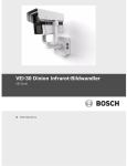
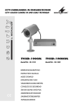
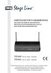
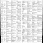
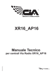
2,4-GHz-FUNKFARBKAMERA und EMPFÄNGER 2.4 GHz WIRELESS COLOUR CAMERA and RECEIVER AV-430SET Best.-Nr. 18.0290 BEDIENUNGSANLEITUNG INSTRUCTION MANUAL MODE D’EMPLOI ISTRUZIONI PER L’USO D A CH F B CH 2 Bevor Sie einschalten … GB Wir wünschen Ihnen viel Spaß mit Ihrem neuen Gerät von MONACOR. Bitte lesen Sie diese Bedienungsanleitung vor dem Betrieb gründlich durch. Nur so lernen Sie alle Funktionsmöglichkeiten kennen, vermeiden Fehlbedienungen und schützen sich und Ihr Gerät vor eventuellen Schäden durch unsachgemäßen Gebrauch. Heben Sie die Anleitung für ein späteres Nachlesen auf. Der deutsche Text beginnt auf der Seite 4. Avant toute installation … Nous vous souhaitons beaucoup de plaisir à utiliser cet appareil MONACOR. Lisez ce mode dʼemploi entièrement avant toute utilisation. Uniquement ainsi, vous pourrez apprendre lʼensemble des possibilités de fonctionnement de lʼappareil, éviter toute manipulation erronée et vous protéger, ainsi que lʼappareil, de dommages éventuels engendrés par une utilisation inadaptée. Conservez la notice pour pouvoir vous y reporter ultérieurement. La version française se trouve page 16. Before switching on … We wish you much pleasure with your new MONACOR unit. Please read these operating instructions carefully prior to operating the unit. Thus, you will get to know all functions of the unit, operating errors will be prevented, and yourself and the unit will be protected against any damage caused by improper use. Please keep the operating instructions for later use. The English text starts on page 10. I Prima di accendere … Vi auguriamo buon divertimento con il vostro nuovo apparecchio di MONACOR. Leggete attentamente le istruzioni prima di mettere in funzione l'apparecchio. Solo così potete conoscere tutte le funzionalità, evitare comandi sbagliati e proteggere voi stessi e l'apparecchio da eventuali danni in seguito ad un uso improprio. Conservate le istruzioni per poterle consultare anche in futuro. Il testo italiano inizia a pagina 21. AV-430SET 11 5 6 7 12 13 14 9 A/V 8 DC8V 1 2 M L 4 1 2 3 4 3 ON 1 2 10 4 3 2 1 3 15 16 17 18 D A Bitte klappen Sie die Seite 3 heraus. Sie sehen dann immer die beschriebenen Bedienelemente und Anschlüsse. CH 1 Übersicht der Bedienelemente und Anschlüsse 1.1 Kamera 1 Kanalschalter 1 2 Kanal 1 Kanal 2 Kanal 3 Kanal 4 2,414 GHz 2,432 GHz 2,450 GHz 2,468 GHz 2 Lichtsensor, schaltet bei zu geringer Beleuchtung die IR-LEDs (3) ein und die Kamera auf Schwarzweißwiedergabe um 3 Infrarot-Leuchtdioden (IR-LEDs) 4 Sonnendach 5 vordere Gehäusehülse, kann zur Kanaleinstellung abgeschraubt werden 6 Antennenanschluss (SMA-Buchse) 7 Sendeantenne 8 Kamerahalterung 9 Kleinspannungskupplung zum Anschluss des beiliegenden Kamera-Netzgerätes 10 Kleinspannungsstecker (3,5/1,35 mm) des KameraNetzgerätes (12 V ) 4 1.2 Empfänger 11 Steckernetzgerät (8 V ) für den Empfänger 12 Anschlussbuchse DC8V für das Empfänger-Netzgerät (11) 13 Buchse A/V für den Audio-/Videoausgang 14 DIP-Schalter für den Betriebsmodus Schalter 1 – 4: Im automatischen Umschaltbetrieb wird zwischen den Kanälen umgeschaltet, deren Schalter in der Position ON stehen; die anderen Kanäle werden übersprungen. Schalter M/L: Zum Umschalten zwischen manueller Kanalwahl (M) und automatischem Umschaltbetrieb (L) 15 Empfangsantenne 16 Antennenanschluss (SMA-Buchse) 17 LEDs zur Anzeige des empfangenem Kanals 18 Taste zur manuellen Kanalwahl 2 Hinweise für den sicheren Gebrauch Die Geräte (Kamera, Empfänger und Netzgeräte) entsprechen allen erforderlichen Richtlinien der EU und sind deshalb mit gekennzeichnet. WARNUNG Die Netzgeräte werden mit lebensgefährlicher Netzspannung (230 V~) versorgt. Nehmen Sie deshalb nie selbst Eingriffe an diesen Geräten vor. Durch unsachgemäßes Vorgehen besteht die Gefahr eines elektrischen Schlages. Beachten Sie auch unbedingt die folgenden Punkte: G Die Kamera darf nicht in der Nähe von Herzschrittmachern (Abstand min. 25 cm) und medizinischen Geräten betrieben werden. Die elektromagnetische Strahlung kann zu Störungen führen. G Die Netzgeräte und der Empfänger sind nur zur Verwendung im Innenbereich geeignet. G Schützen Sie die Geräte vor extremen Temperaturen (zulässiger Einsatztemperaturbereich -10 °C bis +50 °C), die Netzgeräte und den Empfänger zusätzlich vor Tropf- und Spritzwasser sowie hoher Luftfeuchtigkeit. G Nehmen Sie den Empfänger oder die Kamera nicht in Betrieb und ziehen Sie das zugehörige Netzgerät sofort aus der Steckdose, wenn: 1. sichtbare Schäden an einem der Geräte vorhanden sind, 2. nach einem Sturz oder Ähnlichem der Verdacht auf einen Defekt besteht, 3. Funktionsstörungen auftreten. Geben Sie die Geräte in jedem Fall zur Reparatur in eine Fachwerkstatt. G Verwenden Sie für die Reinigung nur ein trockenes, weiches Tuch, niemals Chemikalien oder Wasser. Die Kamera kann auch mit einem angefeuchteten Tuch gesäubert werden. G Werden die Geräte zweckentfremdet, nicht richtig angeschlossen, falsch bedient oder nicht fachgerecht repariert, kann keine Haftung für daraus resul- tierende Sach- oder Personenschäden und keine Garantie für die Geräte übernommen werden. Sollen die Geräte endgültig aus dem Betrieb genommen werden, übergeben Sie sie zur umweltgerechten Entsorgung einem örtlichen Recyclingbetrieb. 3 D A CH Einsatzmöglichkeiten Das Geräteset AV-430SET besteht aus einer 2,4-GHzFunkkamera, dem dazugehörigen Empfänger und zwei Netzgeräten. Es dient zum Aufbau einer drahtlosen Video-Überwachungsanlage. Dazu wird zusätzlich nur noch ein Farbmonitor benötigt. Für die Tonübertragung ist in der Farbkamera ein Mikrofon integriert. Die Kamera ist in einem wetterfesten Gehäuse (IP 66) untergebracht und lässt sich dadurch auch im Außenbereich einsetzen. Bei unzureichender Beleuchtung schaltet der Lichtsensor (2) die 26 IR-LEDs (3) ein und die Kamera auf Schwarzweißbetrieb um. Somit ist bei Dunkelheit auch ohne zusätzliche Beleuchtung eine Überwachung bis zu einer Entfernung von ca. 15 m möglich. Die Übertragungsreichweite hängt stark von den örtlichen Gegebenheiten ab. Bei Sichtverbindung zwischen Kamera und Empfänger kann sie bis zu 100 m betragen. In Gebäuden reduziert sich die Reichweite jedoch durch die Wände und Decken je nach deren Beschaffenheit auf ca. 20 m. Durch die Verwendung einer gewinnbringenden Antenne am Empfänger kann die Reichweite jedoch um ein Mehrfaches erhöht werden. 5 D A CH 3.1 Konformität und Zulassung Hiermit erklärt MONACOR INTERNATIONAL, dass sich das Geräteset AV-430SET in Übereinstimmung mit den grundlegenden Anforderungen und den übrigen einschlägigen Bestimmungen der Richtlinie 1995/5/EG befindet. Die Konformitätserklärung kann im Internet über die Homepage von MONACOR INTERNATIONAL (www.monacor.com) abgerufen werden. Das Geräteset ist für den Betrieb in den EU- und EFTA-Staaten allgemein zugelassen und anmeldeund gebührenfrei. 4 Inbetriebnahme 4.1 Platzierung von Kamera und Empfänger Erfahrungen aus der Praxis haben gezeigt, dass ein optimaler Empfang bei einer Aufstellung in einer Höhe von mindestens 1,5 m bis 2 m über dem Boden erreicht wird. Vor der endgültigen Montage sollte ein Probebetrieb erfolgen, da bereits durch Verschieben der Kamera und des Empfängers um nur einige Zentimeter sich die Übertragungsqualität erheblich ändern kann. Bei Bedarf lässt sich die Kamera an geeigneter Stelle mit der beiliegenden Halterung (8) montieren. Nach dem Lösen der entsprechenden Muttern kann die Kamera geneigt und geschwenkt werden. 6 4.2 Anschlüsse 1) Die Buchse A/V (13) über das beiliegende Adapterkabel mit dem Monitor verbinden: den roten Cinch-Stecker mit dem Audioeingang, den gelben Cinch-Stecker mit dem Videoeingang. 2) Eine der beiden beiliegenden Antennen (15) in die SMA-Buchse (16) stecken. Alternativ kann bei unzureichender Empfangsqualität auch eine 2,4-GHzRichtantenne mit entsprechendem Gewinn verwendet werden, z. B. von MONACOR eine Antenne aus der DX-Serie. 3) Den Stecker des beiliegenden 8-V-Netzgerätes (11) in die Buchse DC8V (12) stecken und das Netzgerät in eine Steckdose (230 V~/50 Hz). 4) Die zweite Antenne (7) in die SMA-Buchse (6) der Kamera stecken. 5) Den Stecker (10) des beiliegenden 12-V-Netzgerätes in die Kupplung (9) der Kamera stecken und das Netzgerät in eine Steckdose (230 V~/50 Hz). Damit sind die Geräte in Betrieb. Nach dem Gebrauch die Netzgeräte zum Ausschalten aus den Steckdosen ziehen. Bei einer Außenmontage müssen die Kleinspannungskupplung (9) und der -stecker (10) wettergeschützt werden. Die unterschiedlichen Stecker der beiden Netzgeräte verhindern ein Vertauschen von Kamera und Empfänger und so eine Beschädigung der Geräte. 4.3 Kanalwahl Die Kamera ist bei Auslieferung auf den Kanal 1 eingestellt. Ist dieser Kanal störungsfrei und wird keine zweite Kamera gleichzeitig betrieben, brauchen die folgenden Informationen nicht beachtet zu werden. Die Funkübertragung erfolgt im 2,4-GHz-Bereich, der für die Geräteserie AV-4xxSET in vier Kanäle aufgeteilt ist. Es können zwei Funkkameras gleichzeitig betrieben werden, um z. B. zwei Räume zu überwachen. Dazu muss immer ein Kanal zwischen den beiden Übertragungskanälen frei bleiben, damit sie sich nicht gegenseitig stören. Folgende Kanalkombinationen sind möglich: Kanal 1 und 3 oder Kanal 1 und 4 oder Kanal 2 und 4 1) Zum Einstellen eines anderen Sendekanals das Sonnendach (4) nach hinten schieben und die vordere Gehäusehülse (5) abschrauben. Mit den DIPSchaltern (1) den Kanal wählen: D 2) Den Betriebsmodus des Empfängers mit dem DIPSchalter M/L (14) wählen: Position M = manuelle Kanalwahl: Den gewünschten Übertragungskanal mit der Taste (18) einstellen. Position L = automatischer Umschaltbetrieb, wenn die Signale mehrerer Kameras empfangen werden sollen: Der Empfänger schaltet alle 4 Sek. zwischen den Kanälen um, deren DIP-Schalter (14) in der Position ON stehen; die anderen Kanäle werden übersprungen. Die LEDs (17) der Kanäle, zwischen denen umgeschaltet wird, leuchten. Die LED des gerade empfangenen Kanals blinkt. A CH 1 2 Kanal 1 Kanal 2 Kanal 3 Kanal 4 2,414 GHz 2,432 GHz 2,450 GHz 2,468 GHz Beim anschließenden Zusammenschrauben auf den richtigen Sitz des Dichtungsrings achten, damit das Kameragehäuse wieder wetterfest ist. 7 D 5 A Kamera Gemeinsame Daten Sendeleistung: . . . . . . . . . . . . < 10 mW (EIRP) Übertragungsfrequenz: . . . . . Kanal 1 Kanal 2 Kanal 3 Kanal 4 CH Technische Daten Reichweite bei Sichtverbindung: . . . . . bis 100 m in Gebäuden: . . . . . . . . . . . bis 20 m Bildabtaster: . . . . . . . . . . . . . . 6,35-mm-CCD-Chip (1/4") Videonorm: . . . . . . . . . . . . . . . CCIR, PAL Anzahl der Bildpunkte: . . . . . . 512 × 582 (hor. × vert.) 2,414 GHz 2,432 GHz 2,450 GHz 2,468 GHz Antenne: . . . . . . . . . . . . . . . . Rundstrahlantenne Modulation/Demodulation: . . . FM Einsatztemperatur: . . . . . . . . . -10 °C bis +50 °C Auflösung: . . . . . . . . . . . . . . . 420 Linien Objektiv: . . . . . . . . . . . . . . . . . 1: 2,0/6,8 mm/39° Mindestbeleuchtung: . . . . . . . 1 Lux (IR-LEDs aus) Änderungen vorbehalten. Audiosignal: . . . . . . . . . . . . . . vom eingebauten Mikrofon Versorgungsspannung: . . . . . 12 V über Netzgerät an 230 V~/50 Hz Stromaufnahme: . . . . . . . . . . 120 mA (IR-LEDs aus) 270 mA (IR-LEDs ein) Empfänger Videoausgang: . . . . . . . . . . . . 1 Vss, 75 Ω Audioausgang: . . . . . . . . . . . . 1 Vss, 600 Ω Versorgungsspannung: . . . . . 8 V über Netzgerät an 230 V~/50 Hz Stromaufnahme : . . . . . . . . . . 180 mA Maße (ohne Antenne): . . . . . . 68 × 18 × 86 mm Gewicht: . . . . . . . . . . . . . . . . . 130 g 8 Diese Bedienungsanleitung ist urheberrechtlich für MONACOR ® INTERNATIONAL GmbH & Co. KG geschützt. Eine Reproduktion für eigene kommerzielle Zwecke – auch auszugsweise – ist untersagt. 9 GB Please unfold page 3. Thus you will always be able to see the operating elements and connections described. 1 Operating Elements and Connections 1.1 Camera 1 Channel switches 1 2 Channel 1 Channel 2 Channel 3 Channel 4 2.414 GHz 2.432 GHz 2.450 GHz 2.468 GHz 2 Light sensor, switches on the IR LEDs (3) in case the illumination is too poor and switches the camera to black-and-white reproduction 3 Infrared light diodes (IR LEDs) 4 Sunshield 5 Front housing sleeve, can be screwed off for channel adjustment 6 Antenna connection (SMA jack) 7 Transmitting antenna 8 Camera support 9 Low voltage inline jack for connection of the supplied camera power supply unit 10 Low voltage plug (3.5/1.35 mm) of the camera power supply unit (12 V ) 10 1.2 Receiver 11 Plug-in power supply unit (8 V ) for the receiver 12 Connection jack DC8V for the power supply unit (11) of the receiver 13 Jack A/V for the audio/video output 14 DIP switches for the operating mode Switches 1 – 4: The automatic channel selection will switch between the channels of which the switches are set to ON; the other channels will be skipped. Switch M/L: To switch between manual channel selection (M) and automatic channel selection (L) 15 Reception antenna 16 Antenna connection (SMA jack) 17 LEDs to indicate the channel received 18 Button for manual channel selection 2 Safety Notes The units (camera, receiver, and power supply units) correspond to all required directives of the EU and are therefore marked with . WARNING The power supply units are supplied with hazardous mains voltage (230 V~). Leave servicing to skilled personnel only. Inexpert handling may cause an electric shock hazard. Please observe the following items in any case: G G G G G G The camera must not be operated near cardiac pacemakers (minimum distance 25 cm) and medical appliances. The electromagnetic radiation may lead to interference. The power supply units and the receiver are suitable for indoor use only. Protect the units against extreme temperatures (admissible ambient temperature range -10 °C to +50 °C), the power supply units and the receiver additionally against dripping water, splash water, and high air humidity. Do not set the receiver or the camera into operation, and immediately disconnect the corresponding power supply unit from the mains socket if 1. there is visible damage to one of the units, 2. a defect might have occurred after a drop or similar accident, 3. malfunctions occur. The units must in any case be repaired by skilled personnel. For cleaning only use a dry, soft cloth, by no means chemicals or water. The camera may also be cleaned with a slightly wet cloth. No guarantee claims for the units and no liability for any resulting personal damage or material damage will be accepted if the units are used for other purposes than originally intended, if they are not correctly connected, operated, or not repaired in an expert way. If the units are to be put out of operation definitively, take them to a local recycling plant for a disposal which is not harmful to the environment. 3 GB Applications The set of units AV-430SET consists of a 2.4 GHz wireless camera, the corresponding receiver, and two power supply units. It serves for setting up a wireless video surveillance system. For this purpose only a colour monitor is additionally required. For the audio transmission a microphone has been integrated into the colour camera. The camera is accommodated in a weatherproof housing (IP 66) and can therefore also be used outdoors. With insufficient illumination the light sensor (2) switches on the 26 IR LEDs (3) and switches the camera to black-and-white operation. Thus, a surveillance in the dark is possible up to a distance of approx. 15 m even without additional illumination. The transmission range largely depends on the local conditions. Without any obstacles between camera and receiver it may be up to 100 m. However, in buildings the range is reduced to approx. 20 m by walls and ceilings, depending on their condition. By using an antenna with gain at the receiver, the range can, however, be increased many times over. 11 GB 3.1 Conformity and Approval Herewith, MONACOR INTERNATIONAL declare that the set of units AV-430SET is in accordance with the basic requirements and the other relevant regulations of the directive 1995/5/EC. The declaration of conformity can be found in the Internet via the MONACOR INTERNATIONAL home page (www.monacor.com). The set of units is licence-free and generally approved for operation in EU and EFTA countries. 4 Operation 4.1 Placing the camera and receiver Practical experience has shown that an optimum reception is achieved when placing the units at a height of minimum 1.5 m to 2 m above the ground. Prior to the final mounting, a trial run is recommended as the transmission quality can substantially be changed by displacing the camera and the receiver by a few centimetres only. If required, the camera can be mounted at a suitable place with the supplied support (8). After releasing the corresponding nuts, the camera can be inclined and moved. 12 4.2 Connections 1) Connect the jack A/V (13) to the monitor via the adapter cable provided: connect the red phono plug to the audio input, connect the yellow phono plug to the video input 2) Connect one of the supplied antennas (15) to the SMA jack (16). Alternatively, with insufficient receiving quality, it is also possible to use a 2.4 GHz directional antenna with corresponding gain, e. g. an antenna of the DX series from MONACOR. 3) Connect the plug of the supplied 8 V power supply unit (11) to the jack DC8V (12) and the power supply unit to a mains socket (230 V~/50 Hz). 4) Connect the second antenna (7) to the SMA jack (6) of the camera. 5) Connect the plug (10) of the supplied 12 V power supply unit to the inline jack (9) of the camera and the power supply unit to a mains socket (230 V~/ 50 Hz). Thus, the units are in operation. After use, disconnect the power supply units from the sockets for switching them off. In case of outdoor mounting, the low voltage inline jack (9) and the low voltage plug (10) must be made weather-resistant. The two power supply units for camera and receiver are provided with different plugs to prevent confusion which may result in damage to the units. 4.3 Channel selection The camera is factory-set to channel 1. If this channel is interference-free and if no second camera is operated at the same time, it is not necessary to pay attention to the following information. The wireless transmission is made in the 2.4 GHz range which has been divided into four channels for the series of units AV-4xxSET. Two wireless cameras can be operated at the same time, e. g. to monitor two rooms. For this purpose always one channel between the two transmission channels must remain free, so that they do not interfere with each other. The following channel combinations are possible: channel 1 and channel 3 or channel 1 and channel 4 or channel 2 and channel 4 When screwing together subsequently, pay attention to the tight fit of the sealing ring so that the camera housing is weatherproof again. 2) Select the operating mode of the receiver with the DIP switch M/L (14): GB Position M = manual channel selection: Adjust the desired transmission channel with the button (18). Position L = automatic channel selection for receiving the signals of several cameras: Every 4 seconds, the receiver will switch between the channels of which the DIP switches (14) are set to ON; the other channels will be skipped. The LEDs (17) of the channels used will light up. The LED of the channel received at the moment will flash. 1) To adjust another transmitting channel, slide the sunshield (4) backwards and screw off the front housing sleeve (5). Select the channel with the DIP switches (1): 1 2 Channel 1 2.414 GHz Channel 2 2.432 GHz Channel 3 2.450 GHz Channel 4 2.468 GHz 13 GB 5 Specifications Camera Receiver Transmitting power: . . . . . . . . < 10 mW (EIRP) Video output: . . . . . . . . . . . . . 1 Vpp, 75 Ω Range without any obstacles: . . . . up to 100 m in buildings: . . . . . . . . . . . . up to 20 m Audio output: . . . . . . . . . . . . . 1 Vpp, 600 Ω Image sensor: . . . . . . . . . . . . 6.35 mm (1/4") CCD chip Supply voltage: . . . . . . . . . . . 8 V via power supply unit connected to 230 V~/50 Hz Video standard: . . . . . . . . . . . CCIR, PAL Current consumption: . . . . . . 180 mA Number of pixels: . . . . . . . . . . 512 × 582 (hor. × vert.) Dimensions (without antenna): 68 x 18 x 86 mm Resolution: . . . . . . . . . . . . . . . 420 lines Weight: . . . . . . . . . . . . . . . . . . 130 g Lens: . . . . . . . . . . . . . . . . . . . 1 : 2.0/6.8 mm/39° Minimum illumination: . . . . . . 1 lux (IR LEDs off) Common specifications Supply voltage: . . . . . . . . . . . 12 V via power supply unit connected to 230 V~/50 Hz Transmitting frequencies: . . . . channel 1 channel 2 channel 3 channel 4 Audio signal: . . . . . . . . . . . . . from the integrated microphone Current consumption: . . . . . . 120 mA (IR LEDs off) 270 mA (IR LEDs on) 2.414 GHz 2.432 GHz 2.450 GHz 2.468 GHz Antenna: . . . . . . . . . . . . . . . . omnidirectional antenna Modulation/demodulation: . . . FM Ambient temperature: . . . . . . -10 °C to +50 °C Subject to technical modification. All rights reserved by MONACOR ® INTERNATIONAL GmbH & Co. KG. No part of this instruction manual may be reproduced in any form or by any means for any commercial use. 14 15 F Ouvrez le présent livret page 3 de manière à visualiser les éléments et branchements. B CH 1 Eléments et branchements 1.1 Caméra 1 Sélecteurs de canaux 1 2 canal 1 canal 2 canal 3 canal 4 2,414 GHz 2,432 GHz 2,450 GHz 2,468 GHz 2 Capteur lumineux : commute les LEDs infrarouges (3) lorsque lʼéclairage est trop faible et commute la caméra sur restitution en mode noir et blanc 3 LEDs infrarouges 4 Pare-soleil 5 Cache boîtier avant : peut être dévissé pour régler les canaux 6 Branchement antenne (prise SMA) 7 Antenne émettrice 8 Support de caméra 9 Prise alimentation pour brancher le bloc secteur livré de la caméra 10 Fiche alimentation (3,5/1,35 mm) du bloc secteur de la caméra (12 V ) 16 1.2 Récepteur 11 Bloc secteur (8 V ) pour le récepteur 12 Prise de branchement DC8V pour le bloc secteur (11) du récepteur 13 Prise A / V pour la sortie audio / vidéo 14 Interrupteurs DIP pour le mode de fonctionnement : Interrupteurs 1 à 4 : En mode de commutation automatique, on commute entre les canaux dont les interrupteurs sont en position ON ; les autres canaux sont sautés. Interrupteur M / L : pour commuter entre sélection manuelle de canal (M) et mode de commutation automatique (L) 15 Antenne de réception 16 Prise antenne (prise SMA) 17 LEDs dʼaffichage du canal reçu 18 Touche pour la sélection manuelle de canal 2 Conseils dʼutilisation et de sécurité Les appareils (caméra, récepteur et blocs secteur) répondent à toutes les directives nécessaires de lʼUnion Européenne et portent donc le symbole . AVERTISSEMENT Les blocs secteur sont alimentés par une tension dangereuse 230 V~. Ne touchez jamais lʼintérieur de ces appareils car en cas de mauvaise manipulation vous pourriez subir une décharge électrique. Respectez impérativement les points suivants : G La caméra ne doit pas fonctionner à proximité de pacemakers (distance minimale 25 cm) et dʼappareils médicaux. Le rayonnement électromagnétique pourrait engendrer des interférences. G Les blocs secteur et le récepteur ne sont conçus que pour une utilisation en intérieur. G Protégez les appareils de températures extrêmes (plage de température de fonctionnement autorisée : -10 °C à +50 °C) et les blocs secteur et le récepteur en plus de tout type de projections dʼeau, des éclaboussures et dʼune humidité élevée. G Ne faites jamais fonctionner le récepteur ou la caméra et débranchez immédiatement le bloc secteur correspondant lorsque : 1. des dommages sur un des appareils apparaissent. 2. après une chute ou un cas similaire, les appareils présentent un défaut. 3. des dysfonctionnements apparaissent. Dans tous les cas, les dommages doivent être réparés par un technicien spécialisé. G Pour le nettoyage, utilisez un chiffon sec et doux, en aucun cas de produits chimiques ou dʼeau. La caméra peut également être nettoyée avec un tissu légèrement humide. G Nous déclinons toute responsabilité en cas de dommages matériels ou corporels résultants si les appareils sont utilisés dans un but autre que celui pour lequel ils ont été conçus, sʼils ne sont pas correctement branchés, utilisés ou pas réparés par une per- sonne habilitée, en outre, la garantie deviendrait caduque. Lorsque les appareils sont définitivement retirés du marché, vous devez les déposer dans une usine de recyclage adaptée pour contribuer à leur élimination non polluante. 3 F B CH Possibilités dʼutilisation Lʼensemble AV-430SET se compose dʼune caméra sans fil 2,4 GHz, de son récepteur correspondant, et de deux blocs secteur. Il permet de constituer une installation de surveillance vidéo sans fil. Dans ce cas, seul un moniteur couleur est, en plus, nécessaire. Pour la transmission audio, la caméra couleur est équipée dʼun microphone. La caméra est proposée dans un boîtier résistant aux intempéries (IP 66) et peut être placée en extérieur. En cas dʼéclairage insuffisant, le capteur de lumière (2) active les 26 LEDs infrarouges (3) et commute la caméra sur le mode noir et blanc. Ainsi, en cas de pénombre, et sans éclairage supplémentaire, une surveillance jusquʼà une distance de 15 m environ est possible. La portée de transmission dépend largement du lieu dʼutilisation ; sans obstacle entre la caméra et le récepteur, elle peut atteindre 100 m. Dans des bâtiments, la portée est réduite par les plafonds et murs à 20 m environ, selon leur composition. Lʼutilisation dʼune antenne amplifiée sur le récepteur permet dʼaugmenter plusieurs fois la portée. 17 F B CH 3.1 Conformité et autorisation Par la présente, MONACOR INTERNATIONAL déclare que lʼensemble AV-430SET se trouve en conformité avec les exigences fondamentales et les autres réglementations inhérentes à la directive 1995/5/CEE. Le certificat de conformité peut être appelé via la page dʼaccueil du site internet de MONACOR INTERNATIONAL (www.monacor.com). Lʼensemble est autorisé dans lʼUnion Européenne et les pays de lʼA.E.L.E. et ne requiert pas de déclaration. 4 Fonctionnement 4.1 Placement de la caméra et du récepteur Lʼexpérience montre que la réception est optimale pour un positionnement des appareils à une hauteur de 1,5 m à 2 m au moins au-dessus du sol. Avant le montage définitif, il est conseillé dʼeffectuer un test car un déplacement de la caméra et du récepteur de quelques centimètres uniquement peut modifier considérablement la qualité de transmission. Si besoin, la caméra peut être montée à lʼendroit adéquat avec le support livré (8). La caméra peut être inclinée et orientée lorsquʼon desserre les écrous correspondants. 18 4.2 Branchements 1) Reliez la prise A/V (13) via le cordon adaptateur livré au moniteur : reliez la fiche RCA mâle rouge à lʼentrée audio, reliez la fiche RCA mâle jaune à lʼentrée vidéo. 2) Reliez une des antennes de réception livrées (15) à la prise SMA (16). Si la qualité de réception est insuffisante, on peut utiliser, à la place, une antenne directionnelle 2,4 GHz avec une amplification adéquate, par exemple, une antenne de la série DX de MONACOR. 3) Placez la fiche du plus bloc secteur 8 V (11) livré dans la prise DC8V (12) et reliez le bloc secteur à une prise 230 V~/50 Hz. 4) Placez la seconde antenne (7) dans la prise SMA (6) de la caméra. 5) Placez la fiche (10) du bloc secteur 12 V livré, dans la prise (9) de la caméra et reliez le bloc secteur à une prise 230 V~/50 Hz. Les appareils sont ainsi en fonction. Après utilisation, débranchez les blocs secteur du secteur pour les éteindre. Pour un montage en extérieur, il faut que la prise et la fiche dʼalimentation (9) et (10) soient protégées contre les intempéries. Les différentes fiches des deux blocs secteur permettent dʼéviter toute inversion de la caméra et du récepteur et ainsi tout dommage sur les appareils. 4.3 Sélection de canaux La caméra est réglée, en usine, sur le canal 1. Si ce canal est sans interférence et si une seconde caméra ne fonctionne pas simultanément, il nʼest pas nécessaire de prendre en compte les informations suivantes. La transmission sans fil sʼeffectue dans la plage 2,4 GHz, divisée, pour la série dʼappareils AV-4xxSET, en quatre canaux. On peut utiliser simultanément deux caméras sans fil pour par exemple surveiller deux pièces. Pour ce faire, un canal doit toujours rester libre entre les deux canaux de transmission pour ne pas quʼils se perturbent simultanément. Les combinaisons de canal suivant sont possibles : Canal 1 et 3 ou Canal 1 et 4 ou Canal 2 et 4 1) Pour régler un autre canal dʼémission, poussez le pare-soleil (4) vers lʼarrière et dévissez la partie avant du boîtier (5). Avec les interrupteurs DIP (1), sélectionnez le canal : 2) Sélectionnez le mode de foncfionnement du récepteur avec lʼinterrupteur DIP M/L (14) : Position M = sélection manuelle de canal : réglez le canal voulu de transmission avec la touche (18). Position L = mode de commutation automatique si des signaux de plusieurs caméras doivent être reçus : le récepteur commute toutes les quatre secondes entre les canaux dont les interrupteurs DIP (14) sont sur la position ON : les autres canaux sont sautés. Les LEDs (17) des canaux entre lesquels il y a commutation, brillent. La LED du canal actuellement reçu clignote. F B CH 1 2 canal 1 canal 2 canal 3 canal 4 2,414 GHz 2,432 GHz 2,450 GHz 2,468 GHz Lorsque vous revissez, faites attention à positionner correctement le joint dʼétanchéité pour que la caméra soit à nouveau protégée des intempéries. 19 F 5 B Caméra Généralités Puissance émission : . . . . . . < 10 mW (EIRP) Fréquence de transmission : CH Caractéristiques techniques Portée En lʼabsence dʼobstacle : . jusquʼà 100 m En intérieur : . . . . . . . . . . . jusquʼà 20 m Système : . . . . . . . . . . . . . . . puce CCD 6,35 mm (1/4") Norme vidéo : . . . . . . . . . . . . CCIR, PAL Nombre de points : . . . . . . . . 512 × 582 (hor. × vert.) Antenne : canal 1 canal 2 canal 3 canal 4 2,414 GHz 2,432 GHz 2,450 GHz 2,468 GHz . . . . . . . . . . . . . . . omnidirectionnelle Modulation/Démodulation : . . FM Température fonc. : . . . . . . . .-10 °C à +50 °C Résolution : . . . . . . . . . . . . . . 420 lignes Objectif : . . . . . . . . . . . . . . . . 1 : 2,0/6,8 mm/39° Tout droit de modification réservé. Luminosité minimale : . . . . . . 1 lux (LEDs IR éteintes) Signal audio : . . . . . . . . . . . . du micro intégré Alimentation : . . . . . . . . . . . . 12 V par bloc secteur relié à 230 V~/50 Hz Consommation : . . . . . . . . . . 120 mA (LEDs IR éteintes) 270 mA (LEDs IR allumées) Récepteur Sortie vidéo : . . . . . . . . . . . . . 1 Vcc, 75 Ω Sortie audio : . . . . . . . . . . . . . 1 Vcc, 600 Ω Alimentation : . . . . . . . . . . . . 8 V par bloc secteur relié à 230 V~/50 Hz Consommation : . . . . . . . . . . 180 mA Dimensions (sans antenne) : 68 × 18 × 86 mm Poids : . . . . . . . . . . . . . . . . . . 130 g 20 Notice dʼutilisation protégée par le copyright de MONACOR ® INTERNATIONAL GmbH & Co. KG. Toute reproduction même partielle à des fins commerciales est interdite. Vi preghiamo di aprire la pagina 3. Così vedrete sempre gli elementi di comando e i collegamenti descritti. 1 Elementi di comando e collegamenti 1.1 Telecamera 1 Selettore canali 1 2 Canale 1 Canale 2 Canale 3 Canale 4 2,414 GHz 2,432 GHz 2,450 GHz 2,468 GHz 2 Sensore ottico, accende i LED IR (3) in caso di luce insufficiente e attiva la riproduzione in b/n per la telecamera 3 Diodi luminosi a infrarossi (LED IR) 4 Parasole 5 Parte anteriore del contenitore, può essere svitata per lʼimpostazione dei canali 6 Contatto per lʼantenna (presa SMA) 7 Antenna di trasmissione 8 Supporto per la telecamera 9 Presa per alimentazione DC per il collegamento con lʼalimentatore della telecamera in dotazione 10 Spinotto per alimentazione DC (3,5/1,35 mm) dellʼalimentatore della telecamera (12 V ) 1.2 Ricevitore 11 Alimentatore a spina (8 V ) per il ricevitore 12 Presa di contatto DC8V per lʼalimentatore del ricevitore (11) 13 Presa A/V per lʼuscita audio/video 14 DIP-switch per il modo di funzionamento Switch 1 – 4: Nel funzionamento con cambio automatico si cambia fra i canali i cui switch sono in posizione ON; gli altri canali vengono saltati. Switch M/L: Per cambiare fra scelta manuale (M) del canale e cambio automatico (L) 15 Antenna di ricezione 16 Contatto per lʼantenna (presa SMA) 17 LED per indicare il canale ricevuto 18 Tasto per la scelta manuale del canale 2 I Avvertenze di sicurezza Gli apparecchi (telecamera, ricevitore e alimentatori) sono conformi a tutte le direttive richieste dellʼUE e pertanto portano la sigla . AVVERTIMENTO Gli alimentatori funzionano con pericolosa tensione di rete (230 V~). Non intervenire mai personalmente al loro interno. La manipolazione scorretta può provocare delle scariche elettriche pericolose. 21 I 22 Si devono osservare assolutamente i seguenti punti: G La telecamera non deve essere messa in uso vicino a dei pace-maker (distanza minima 25 cm) e apparecchi medici. I raggi elettromagnetici possono provocare dei disturbi. G Gli alimentatori e il ricevitore sono adatti solo per lʼuso allʼinterno di locali. G Proteggere gli apparecchi da temperature estreme (temperatura dʼimpiego ammessa fra -10 °C e +50 °C) gli alimentatori e il ricevitore dallʼacqua gocciolante e dagli spruzzi dʼacqua nonché da alta umidità dellʼaria. G Non mettere in funzione il ricevitore o la telecamera e staccare subito lʼalimentatore dalla presa di rete se: 1. uno degli apparecchi presenta dei danni visibili; 2. dopo una caduta o dopo eventi simili sussiste il sospetto di un difetto; 3. gli apparecchi non funzionano correttamente. Per la riparazione rivolgersi sempre ad unʼofficina competente. G Per la pulizia usare solo un panno morbido, asciutto; non impiegare in nessun caso acqua o prodotti chimici. La telecamera può essere pulita anche con un panno inumidito. G Nel caso dʼuso improprio, di collegamenti sbagliati, dʼimpiego scorretto o di riparazione non a regola dʼarte degli apparecchi, non si assume nessuna responsabilità per eventuali danni consequenziali a persone o a cose e non si assume nessuna garanzia per gli apparecchi. Se si desidera eliminare gli apparecchi definitivamente, consegnarli per lo smaltimento ad unʼistituzione locale per il riciclaggio. 3 Possibilità dʼimpiego Il set di apparecchi AV-430SET è composto da una telecamera senza fili a 2,4 GHz, dal relativo ricevitore, e da due alimentatori. Serve per creare un impianto di sorveglianza video senza fili. È richiesto in più soltanto un monitor a colori. Per la trasmissione audio, nella telecamera è íntegrato un microfono. La telecamera è sistemata in un contenitore resistente alle intemperie (IP 66) e perciò è utilizzabile anche allʼesterno. Nel caso di luce insufficiente, il sensore ottico (2) accende i 26 LED IR (3) e attiva nella telecamera il funzionamento in b/n. Quindi anche allʼoscurità è possibile una sorveglianza fino ad una distanza di 15 m ca. senza illuminazione supplementare. La portata di trasmissione dipende fortemente dalle condizioni locali. Se non ci sono ostacoli fra trasmettitore e ricevitore può arrivare fino a 100 m. Negli edifici, la portata è ridotta per via delle pareti e dei soffitti, a seconda delle loro caratteristiche, a 20 m ca. Impiegando unʼantenna con guadagno sul ricevitore, la portata può essere aumentata più volte. 3.1 Conformità e omologazione La MONACOR INTERNATIONAL dichiara che il set di apparecchi AV-430SET è conforme a tutti i requisiti di base e alle rimanenti disposizioni in materia della direttiva 1995/5/CE. La dichiarazione di conformità può essere scaricata in Internet dal sito di MONACOR INTERNATIONAL (www.monacor.com). Il set di apparecchi AV-430SET è omologato per lʼimpiego negli stati dellʼUE e dellʼEFTA, non richiede registrazione ed è esento da tasse. 4 Messa in funzione 4.1 Posizionamento di telecamera e ricevitore Lʼesperienza pratica ha dimostrato che si ottiene una ricezione ottimale posizionando gli apparecchi ad unʼaltezza di non meno di 1,5 m a 2 m dal pavimento. Prima del montaggio definitivo conviene fare delle prove, perché uno spostamento della telecamera e del ricevitore di pochi centimetri può modificare notevolmente la qualità di trasmissione. Se necessario, la telecamera può essere montata in un luogo adatto per mezzo del supporto (8) in dotazione. Dopo aver allentato le relative viti, la telecamera può essere inclinata e girata. 4.2 Collegamenti 1) Collegare la presa A/V (13) con il monitor servendosi del cavo adattatore in dotazione: la spina RCA rossa con lʼingresso audio la spina RCA gialla con lʼingresso video. 2) Inserire una delle due antenne in dotazione (15) nella presa SMA (16). In alternativa, e nel caso di qualità scarsa di ricezione, si può usare anche unʼantenna direzionale di 2,4 GHz con guadagno, p. es. unʼantenna della serie DX di MONACOR. 3) Inserire lo spinotto dellʼalimentatore 12 V (11) nella presa DC8V (12) e inserire lʼalimentatore in una presa di rete (230 V~/50 Hz). 4) Inserire la seconda antenna (7) nella presa SMA (6) della telecamera. 5) Inserire lo spinotto (10) dellʼalimentatore 12 V nella presa (9) della telecamera e inserire lʼalimentatore in una presa di rete (230 V~/50 Hz). In questo modo, gli apparecchi sono in funzione. Dopo lʼuso, per spegnere gli apparecchi, staccare gli alimentatori dalle prese. Nel caso di un montaggio allʼesterno, la presa (9) e lo spinotto (10) per alimentazione DC devono essere protetti contro le intemperie. I connettori differenti fra i due alimentatori escludono uno scambio fra telecamera e ricevitore e quindi rendono impossibile il danneggiamento degli apparecchi. I 23 I 4.3 Scelta del canale Al momento della consegna, la telecamera è messo sul canale 1. Se tale canale è senza interferenze e se non si impiega una seconda telecamera contemporaneamente, le seguenti informazioni non hanno importanza. La trasmissione radio avviene nel settore dei 2,4 GHz, suddiviso per la serie di apparecchi AV-4xxSET in quattro canali. Si possono usare due telecamere senza fili contemporaneamente, p. es. per sorvegliare due ambienti. In questo caso è necessario che un canale rimanga sempre libero fra i due canali di trasmissione per evitare delle interferenze. Sono possibili le seguenti combinazioni di canali: canali 1 e 3 o canali 1 e 4 o canali 2 e 4 1) Per impostare una altro canale di trasmissione, spostare il parasole (4) allʼindietro e svitare la parte anteriore (5) del contenitore. Selezionare il canale con i DIP-switch (1): 1 2 Canale 1 Canale 2 Canale 3 Canale 4 2,414 GHz 2,432 GHz 2,450 GHz 2,468 GHz Avvitando di nuovo il contenitore fare attenzione alla corretta posizione della guarnizione per essere sicuri che il contenitore sia resistente alle intemperie. 24 2) Scegliere il modo di funzionamento del ricevitore con il DIP-switch M/L (14): Posizione M = scelta manuale del canale: impostare il canale desiderato per la trasmissione con il tasto (18). Posizione L = funzionamento a cambio automatico, se si devono ricevere i segnali di più telecamere: il ricevitore cambia ogni 4 secondi fra i canali i cui DIP-switch (14) si trovano in posizione ON; gli altri canali vengono saltati. I LED (17) dei canali, fra i quali ha luogo il cambio, si accendono. Il LED del canale che sta ricevendo, lampeggia. 5 Dati tecnici I Telecamera Dati comuni Potenza di trasmissione: . . . . < 10 mW (EIRP) Frequenza di trasmissione: . . canale 1 canale 2 canale 3 canale 4 Portata a vista libera: . . . . . . . . . . . fino a 100 m in edifici: . . . . . . . . . . . . . . fino a 20 m Sensore ottico: . . . . . . . . . . . . chip CCD 6,35 mm (1/4") Norma video: . . . . . . . . . . . . . CCIR, PAL Numero pixel: . . . . . . . . . . . . . 512 × 582 (orizz. × vert.) 2,414 GHz 2,432 GHz 2,450 GHz 2,468 GHz Antenna: . . . . . . . . . . . . . . . . onnidirezionale Modulazione/demodulazione: FM Temperatura dʼesercizio: . . . . -10 °C a +50 °C Risoluzione: . . . . . . . . . . . . . . 420 linee Obiettivo: . . . . . . . . . . . . . . . . 1: 2,0/6,8 mm/39° Con riserva di modifiche tecniche. Illuminazione minima: . . . . . . 1 Lux (LED IR spenti) Segnale audio: . . . . . . . . . . . . dal microfono integrato Alimentazione: . . . . . . . . . . . . 12 V tramite alimentatore con 230 V~/50 Hz Potenza assorbita: . . . . . . . . . 120 mA (LED IR spenti) 270 mA (LED IR accesi) Ricevitore Uscita video: . . . . . . . . . . . . . 1 Vpp, 75 Ω Uscita audio: . . . . . . . . . . . . . 1 Vpp, 600 Ω Alimentazione: . . . . . . . . . . . . 8 V tramite alimentatore con 230 V~/50 Hz Potenza assorbita: . . . . . . . . . 180 mA Dimensioni (senza antenna): . 68 × 18 × 86 mm Peso: . . . . . . . . . . . . . . . . . . . 130 g La MONACOR ® INTERNATIONAL GmbH & Co. KG si riserva ogni diritto di elaborazione in qualsiasi forma delle presenti istruzioni per lʼuso. La riproduzione – anche parziale – per propri scopi commerciali è vietata. 25 ® Copyright © by MONACOR INTERNATIONAL GmbH & Co. KG, Bremen, Germany. All rights reserved. A-0475.99.03.06. 2008